MAX4551CEE中文资料
MAX7491中文资料

Stresses beyond those listed under “Absolute Maximum Ratings” may cause permanent damage to the device. These are stress ratings only, and functional operation of the device at these or any other conditions beyond those indicated in the operational sections of the specifications is not implied. Exposure to absolute maximum rating conditions for extended periods may affect devic Rev 0; 7/00
Dual Universal Switched-Capacitor Filters
General Description
The MAX7490/MAX7491 consist of two identical lowpower, low-voltage, wide dynamic range, Rail-to-Rail®, 2nd-order switched-capacitor building blocks. Each of the two filter sections, together with two to four external resistors, can generate all standard 2nd-order functions: bandpass, lowpass, highpass, and notch (band reject). Three of these functions are simultaneously available. Fourth-order filters can be obtained by cascading the two 2nd-order filter sections. Similarly, higher order filters can easily be created by cascading multiple MAX7490/MAX7491s. Two clocking options are available: self-clocking (through the use of an external capacitor) or external clocking for tighter cutoff frequency control. The clockto-center frequency ratio is 100:1. Sampling is done at twice the clock frequency, further separating the cutoff frequency and Nyquist frequency. The MAX7490/MAX7491 have an internal rail splitter that establishes a precise common voltage needed for single-supply operation. The MAX7490 operates from a single +5V supply and the MAX7491 operates from a single +3V supply. Both devices feature a low-power shutdown mode and come in a 16-pin QSOP package.
MAX4553EEE中文资料

Pin Configurations/Functional Diagrams/Truth TablesTO Nhomakorabea VIEW
IN1 COM1 NC1 VGND NC4 COM4 IN4 1 2 3 4 5 6 7 8 16 15 14 13 IN2 COM2 NC2 V+ N.C. NC3 COM3 IN3 IN1 COM1 NO1 VGND NO4 COM4 IN4 1 2 3 4 5 6 7 8 16 15 14 13 IN2 COM2 NO2 V+ N.C. NO3 COM3 IN3 IN1 COM1 NO1 VGND NO4 COM4 IN4 1 2 3 4 5 6 7 8 16 15 14 13 IN2 COM2 NC2
____________________________Features
o ±15kV ESD Protection per IEC 1000-4-2 o +2V to +12V Single Supply ±2V to ±6V Dual Supplies o 120Ω Signal Paths with ±5V Supplies o Low Power Consumption: <1µW o 4 Separately Controlled SPST Switches o Rail-to-Rail Signal Handling o Pin-Compatible with Industry-Standard DG211/DG212/DG213 o TTL/CMOS-Compatible Inputs with Dual ±5V or Single +5V Supply
QSOP/SO/DIP
MAX4553 SWITCHES 1, 4 OFF ON SWITCHES 2, 3 ON OFF
MAX4145EEE+T中文资料
1
For free samples and the latest literature, visit or phone 1-800-998-8800. For small orders, phone 1-800-835-8769.
元器件交易网
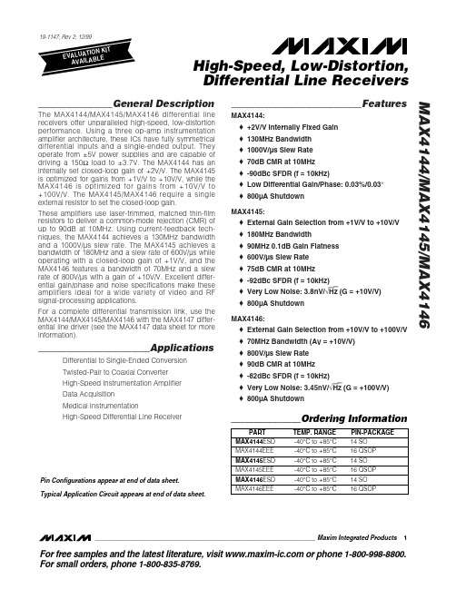
High-Speed, Low-Distortion, Differential Line Receivers MAX4144/MAX4145/MAX4146
ABSOLUTE MAXIMUM RATINGS
Supply Voltage (VCC to VEE) ..................................................12V Voltage on IN_, SHDN, REF, OUT, SENSE, RG_.................................(VEE - 0.3V) to (VCC + 0.3V) Short-Circuit Duration to Ground ........................................10sec Input Current (IN_, RG_)...................................................±10mA Output Current................................................................±120mA Continuous Power Dissipation (TA = +70°C) 14-Pin SO (derate 8.33mW/°C above +70°C)..............667mW 16-Pin QSOP (derate 8.33mW/°C above +70°C).........667mW Operating Temperature Range ...........................-40°C to +85°C Storage Temperature Range .............................-65°C to +150°C Lead Temperature (soldering, 10sec) .............................+300°C
MAX9591EVKIT+;中文规格书,Datasheet资料

General DescriptionThe MAX9591 evaluation kit (EV kit) demonstrates the MAX9591 reference-voltage generator for gamma cor-rection in TFT-LCD panels, such as those found in high-resolution TVs, high-end monitors, or for general industrial reference-voltage generation. The MAX9591EV kit provides 14 programmable reference-voltage outputs (DAC outputs) and four static buffered refer-ence-voltage outputs (reference outputs). The EV kit uses a 9V to 20V DC power supply for powering the application circuit.The EV kit features a USB-to-I 2C interface circuit.Windows ®2000/XP/Vista ®-compatible software, with a graphical user interface (GUI), is available for exercis-ing the MAX9591 features. The EV kit can also connect to a user-supplied I 2C interface circuit for stand-alone MAX9591 operation.The MAX9591 EV kit can also be used to evaluate the MAX9590ETU+.Features♦14 8-Bit Programmable Reference Voltages (DAC Outputs)♦Four Static Buffered Reference Voltages (Reference Outputs)♦400mA Peak Current on Reference Outputs and DAC Outputs 1, 7, 8, and 14♦200mA Peak Current on DAC Outputs 2–6 and 9–13♦9V to 20V DC Power-Supply Operation ♦USB-Powered USB-to-I 2C Interface Circuit ♦Windows 2000/XP/Vista (32-Bit)-Compatible Software♦Lead-Free and RoHS Compliant ♦Proven PCB Layout♦Fully Assembled and TestedEvaluates: MAX9590/MAX9591MAX9591 Evaluation Kit19-4258; Rev 0; 8/08For pricing, delivery, and ordering information, please contact Maxim Direct at 1-888-629-4642,or visit Maxim’s website at .Ordering Information+Windows and Windows Vista are registered trademarks of Microsoft Corp.________________________________________________________________Maxim Integrated Products1E v a l u a t e s : M A X 9590/M A X 9591MAX9591 Evaluation Kit 2_______________________________________________________________________________________Quick StartRequired Equipment Before beginning, the following equipment is needed:•MAX9591 EV kit (USB cable included)• A user-supplied Windows 2000/XP/Vista PC with a spare USB port•9V to 20V DC power supply at 500mA•One digital voltmeter (DVM)Note:I n the following sections, software-related items are identified by bolding. Text in bold refers to items directly from the EV kit software. Text in bold and under-lined refers to items from the Windows operating system.Procedure The MAX9591 EV kit is fully assembled and tested. Follow the steps below to verify board operation:1)Visit /evkitsoftware to down-load the latest version of the EV kit software, 9591Rxx.ZIP. Save the EV kit software to a tempo-rary folder and uncompress the ZIP file.2)Install the EV kit software on your computer by run-ning the I NSTALL.EXE program inside the tempo-rary folder. The program files are copied and icons are created in the Windows Start | Programs menu.3)Connect the USB cable from the PC to the EV kitboard. A N ew Hardware Found window pops up when installing the USB driver for the first time. I f you do not see a window that is similar to the one described above after 30s, remove the USB cable from the board and reconnect it. Administrator privi-leges are required to install the USB device driver on Windows.4)Follow the directions of the Add N ew HardwareWizard to install the USB device driver. Choose the Search for the best driver for your device option.Specify the location of the device driver to be C:\Program Files\MAX9591(default installation directory) using the Browse button. During devicedriver installation, Windows might show a warning message indicating that the device driver Maxim uses does not contain a digital signature. This is not an error condition and it is safe to proceed with installation. Refer to the USB_Driver_Help.PDF doc-ument included with the software if there are any problems during this step.5)Once the software and hardware installation is com-plete, disconnect the USB cable from the EV kit.6)Verify that shunts are installed on:•Jumper JU5: Pins 1-2 (on-board 3.3V digital power supply)•Jumper JU6: Pins 1-2 (MAX9591 write address = 0xE8)7)Connect the USB cable to the EV kit.8)Connect the DVM negative terminal to the AGNDPCB pad next to the REFL_L PCB pad.9)Connect a voltage probe to the DVM positive terminalfor later use.10)Set the power supply to 15V and disable the power-supply output.11)Connect the power-supply positive terminal to theAVDD PCB pad and the negative terminal to the AGND PCB pad next to AVDD.12)Enable the power-supply output.13)Start the MAX9591 EV kit software by opening itsicon in the Start | Programs menu. The EV kit soft-ware main window appears, as shown in Figure 1. 14)Use the DVM voltage probe to measure the refer-ence input voltages on the REFU_H, REFU_L, REFL_H and REFL_L PCB pads, and type those val-ues into the corresponding edit boxes of the Reference Voltages (V)group box.15)Press the Quick Start button.16)Use the DVM voltage probe to verify that the DACoutput voltages are close to the voltages shown in the Output (V)edit boxes for the respective channel. Evaluates: MAX9590/MAX9591MAX9591 Evaluation Kit_______________________________________________________________________________________3E v a l u a t e s : M A X 9590/M A X 9591Detailed Description of SoftwareThe MAX9591 evaluation kit (EV kit) software main win-dow is shown in Figure 1. The GUI software automati-cally detects the MAX9591 device address and displays it in the I2C Address Setting drop-down list and in the software status bar. The DAC output volt-ages in the Upper DAC Channels /Lower DAC Channels group boxes are calculated using the upper and lower reference input voltages on PCB pads REFU_H, REFU_L, REFL_H, and REFL_L. The reference input voltages MUST be measured at the appropriate PCB pads and the values entered in the respective Reference Voltages (V)edit boxes for the DAC output calculations to be correct.Upon I C startup, the DAC outputs wake up in high-impedance mode. To exit high-impedance mode, click the Quick Start button or perform the following steps:1)Select the Bank A radio button in the Output BankSelect group box. Select the Bank A Register Settings tab.2)Select the Burst radio button in the RegisterAddressing Mode group box.3)Modify any of the DAC channel’s register values.See the Output Register Values section for more information.4)Press the Load All Values To Registers button.5)Select the Bank B radio button in the Output BankSelect group box. Select the Bank B Register Settings tab. Repeat steps 3 and 4.The Quick Start button loads all bank A and bank B registers with a predefined set of values.MAX9591 Evaluation Kit 4_______________________________________________________________________________________Figure 1. MAX9591 Evaluation Software Main WindowRegister banks A and B are selectable using the radio buttons in the Output Bank Select group box. Register values are modified and loaded to registers using the buttons, edit boxes, and scrollbars of the Bank _Register Settings tabs where _ is either A or B .I 2C Address SettingThe MAX9591’s I 2C slave address is displayed in the status bar of the software window and the I2C Address Setting drop-down list. I f an address is manually selected in the drop-down list, the software verifies the address and changes the address displayed appropri-ately. If no acknowledge is received from the EV kit, a pop-up window is opened directing the user to properly set jumper JU6 on the EV kit. I f the Auto Detect Address checkbox is checked, the software automati-cally detects the I 2C address of the MAX9591.Upper and Lower DAC Output VoltagesThe upper and lower DAC output voltages are generat-ed using an on-board resistor-divider network. The user can also apply external references to the REFU_H,REFU_L, REFL_H, and REFL_L, and AGND PCB pads.The voltages on these four pads MUST be captured and typed into the appropriate edit boxes in the Reference Voltages (V)group box for the calculated DAC output voltages shown in the Upper DAC Channels/Lower DAC Channels group boxes to be correct.The transfer function for the upper DAC channels is:The transfer function for the lower DAC channels is:In both equations, D is the decimal register value. Refer to the MAX9591 IC data sheet for more details.When the evaluation software is run for the first time, the reference input-voltage values in the Reference Voltages (V)group box are loaded from an initialization file (REF.INI). When the program is closed, the current values are logged in to the initialization file. The next time the program is run, the latest values are loaded automatically.Output Bank SelectThe Bank A , Bank B , and A, B Alternating radio but-tons in the Output Bank Select group box choose the set of reference voltages buffered to the outputs between bank A, bank B, or alternating between banks A and B, with 1s hold time for each bank.Output Register ValuesEach DAC channel’s register value can be set in three different ways within the Upper DAC Channels /Lower DAC Channels group boxes by:1)Moving the channel’s scrollbar.2)Typing register values directly into the channel’sReg Value edit box (decimal 8-bit equivalent).3)Typing the expected output voltage in the chan-nel’s Output (V)edit box. The software uses a reg-ister value that generates a voltage closest to the desired voltage value.When a register value is changed, the corresponding field changes its color to red. A user should synchro-nize the GUI fields and actual device registers by pressing either the channel’s Load button (in single mode) or the Load All Values To Registers button (in burst mode).The Load All Reg Values From File button is used to load all the register values and reference voltages from a text file. The Save All Reg Values To File button is used to save all the register values and reference volt-ages on the current GUI to a user-named text file.Register read/write operations can take place regard-less of the output bank setting; for example, the user can change bank B registers when bank A is buffered to the outputs.Register Addressing ModeThe Burst and Single radio buttons in the Register Addressing Mode group box set the MAX9591 soft-ware operation mode.When the Burst radio button is selected, all registers for a single bank are updated using the Load All Values To Registers or Load All Reg Values From File buttons. The individual register’s Load buttons are disabled.When the Single radio button is selected, single regis-ter values are updated using the individual register’s Load buttons. The Load All Values To Registers and Load All Reg Values From File buttons are disabled.Register Mode I 2C ActivityThe Register Mode I2C Activity group box is used for the convenience of debugging when the Single radio button is selected. When an individual register is writ-ten, the bits sent to the MAX9591 through the I 2C inter-face are displayed.Evaluates: MAX9590/MAX9591MAX9591 Evaluation Kit_______________________________________________________________________________________5E v a l u a t e s : M A X 9590/M A X 9591Advanced User InterfaceA serial interface can be used by advanced users by selecting Options | Interface (Advanced Users)from the menu bar.Click on the 2-wire interface tab shown in Figure 2.Press the Hunt for active listeners button to obtain the current MAX9591 slave address in the Target Device Address combo box. I n the General commands tab,select 1 – SMBusWriteByte(addr,cmd,data8)from the Command (SMBus Protocols, Raw Block Read/Write,EEPROM Read/Write)drop-down list. Enter the desired values into the Command byte and Data Out combo boxes and then press the Execute button.Detailed Description of HardwareThe MAX9591 evaluation kit (EV kit) demonstrates the MAX9591 reference-voltage generator in a 38-pin TQFN surface-mount package with an exposed pad.EV kit applications include gamma correction in TFT-LCD panels, such as those found in high-resolution TVs, high-end monitors, or for general industrial refer-ence-voltage generation. The MAX9591 EV kit provides 14 programmable reference-voltage outputs (DAC out-puts) and four static buffered reference-voltage outputs (DAC reference outputs) using four input reference volt-ages (DAC reference inputs).To monitor the MAX9591 EV kit’s 14 DAC outputs (OUT1–OUT14) and four reference outputs (OUT_REFU_H,OUT_REFU_L, OUT_REFL_H, and OUT_REFL_L), useMAX9591 Evaluation Kit 6_______________________________________________________________________________________Figure 2. Advanced I 2C Users Interface Window | 2-Wire Interface Tabheader J1 or the labeled test points. Reference outputs OUT_REFU_H, OUT_REFU_L, OUT_REFL_H, OUT_REFL_L,and DAC outputs OUT1, OUT7, OUT8, and OUT14 pro-vide 400mA of peak current. DAC outputs OUT2–OUT6and OUT9–OUT13 provide 200mA of peak current. Stay within the MAX9591 I C’s power rating. Refer to the MAX9591 IC data sheet for more information.The on-board resistor-divider network (R37–R41) gener-ates the reference inputs (REFU_H, REFU_L, REFL_H,and REFL_L). The user can also apply external refer-ence voltages to the REFU_H, REFU_L, REFL_H, and REFL_L PCB pads after removing R37–R41.The EV kit uses a 9V to 20V DC power supply, connected across the AVDD and AGND PCB pads, for powering the EV kit application circuit. The EV kit might require up to 500mA of supply current depending on output loading.Digital Supply ConfigurationThe MAX9591 EV kit provides two options to power the MAX9591 digital supply input (DVDD). DVDD can oper-ate from the 3.3V supply generated by the USB-to-I 2C interface circuit or from a user-supplied 2.7V to 5.5V DC power supply connected across the DVDD and DGND PCB pads. See Table 1 to configure DVDD using jumper JU5.Caution:Always ensure that DVDD is powered before AVDD.MAX9591 Slave Address DescriptionThe MAX9591 I 2C slave address can be set by jumper JU6. The slave address can be set to one of four dif-ferent addresses. See Table 2 for slave address configuration.Stand-Alone User-SuppliedI 2C CommunicationThe EV kit can be used in stand-alone operation to interface with a user’s I 2C system without using a PC.To use the MAX9591 EV kit with a user-supplied I 2C interface, perform the following steps:1)Viewing Figure 6, cut the SDA, SCL, STD_REG, andBANK_SEL traces immediately to the left of the cor-responding PCB pad.2)Disconnect the USB cable from the EV kit.3)Move jumper JU5 shunt to pins 2-3.4)Connect the positive terminal of a user-supplied 2.7Vto 5.5V DC power supply to the DVDD PCB pad and the negative terminal to the nearby DGND PCB pad.5)I nstall 2.2k Ω0603 surface-mount resistors at loca-tions R35 and R36 to pull up user-supplied signals SDA and SCL to DVDD if needed.6)Connect the user-supplied I 2C interface signals,general-purpose output (GPO) control signals, and signal ground return to the EV kit PCB pads, as shown in Table 3.Evaluates: MAX9590/MAX9591MAX9591 Evaluation Kit_______________________________________________________________________________________7Table 2. Slave Address Description***Disconnect the USB cable from the EV kit.E v a l u a t e s : M A X 9590/M A X 9591MAX9591 Evaluation Kit 8_______________________________________________________________________________________Figure 3a. MAX9591 EV Kit Schematic—Application Circuit (Sheet 1 of 2)Evaluates: MAX9590/MAX9591MAX9591 Evaluation Kit_______________________________________________________________________________________9Figure 3b. MAX9591 EV Kit Schematic—USB-to-I C Circuit (Sheet 2 of 2)E v a l u a t e s : M A X 9590/M A X 9591MAX9591 Evaluation Kit 10______________________________________________________________________________________Figure 4. MAX9591 EV Kit Component Placement Guide—Component SideFigure 5. MAX9591 EV Kit PCB Layout—Component Side分销商库存信息: MAXIMMAX9591EVKIT+。
MAX941CSA中文资料

ELECTRICAL CHARACTERISTICS
(V+ = 2.7V to 6.0V, TA = TMIN to TMAX, unless otherwise noted. Typical values are at TA = +25°C. See Note 14.)
PARAMETER Positive Supply Voltage Input Voltage Range
Internal hysteresis ensures clean output switching, even with slow-moving input signals. The MAX941 features latch enable and device shutdown.
The single MAX941 and dual MAX942 are offered in a tiny µMAX package. Both the single and dual MAX942 are available in 8-pin DIP and SO packages. The quad MAX944 comes in 14-pin DIP and narrow SO packages.
__________________________________________________________Pin Configurations
TOP VIEW
MAX941
V+ 1 IN+ 2 IN- 3 SHDN 4
8 N.C. 7 OUT 6 GND 5 LATCH
DIP/SO/µMAX
SYMBOL V+
V
MIN TYP MAX UNITS
max3485esa中文资料
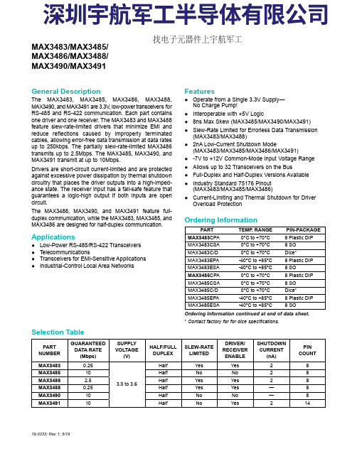
General Description The MAX3483, MAX3485, MAX3486, MAX3488,MAX3490, and MAX3491 are 3.3V , low-power transceivers forRS-485 and RS-422 communication. Each part containsone driver and one receiver. The MAX3483 and MAX3488feature slew-rate-limited drivers that minimize EMI andreduce reflections caused by improperly terminatedcables, allowing error-free data transmission at data ratesup to 250kbps. The partially slew-rate-limited MAX3486transmits up to 2.5Mbps. The MAX3485, MAX3490, andMAX3491 transmit at up to 10Mbps.Drivers are short-circuit current-limited and are protectedagainst excessive power dissipation by thermal shutdowncircuitry that places the driver outputs into a high-imped-ance state. The receiver input has a fail-safe feature thatguarantees a logic-high output if both inputs are opencircuit.The MAX3488, MAX3490, and MAX3491 feature full-duplex communication, while the MAX3483, MAX3485, andMAX3486 are designed for half-duplex communication.Applications ●Low-Power RS-485/RS-422 Transceivers ●Telecommunications ●Transceivers for EMI-Sensitive Applications ●Industrial-Control Local Area NetworksFeatures●Operate from a Single 3.3V Supply—No Charge Pump!●Interoperable with +5V Logic ●8ns Max Skew (MAX3485/MAX3490/MAX3491)●Slew-Rate Limited for Errorless Data Transmission (MAX3483/MAX3488)●2nA Low-Current Shutdown Mode (MAX3483/MAX3485/MAX3486/MAX3491)●-7V to +12V Common-Mode Input Voltage Range ●Allows up to 32 Transceivers on the Bus ●Full-Duplex and Half-Duplex Versions Available ●Industry Standard 75176 Pinout (MAX3483/MAX3485/MAX3486)●Current-Limiting and Thermal Shutdown for Driver Overload Protection 19-0333; Rev 1; 5/19Ordering Information continued at end of data sheet.*Contact factory for for dice specifications.PARTTEMP . RANGE PIN-PACKAGE MAX3483CPA0°C to +70°C 8 Plastic DIP MAX3483CSA0°C to +70°C 8 SO MAX3483C/D0°C to +70°C Dice*MAX3483EPA-40°C to +85°C 8 Plastic DIP MAX3483ESA-40°C to +85°C 8 SO MAX3485CPA0°C to +70°C 8 Plastic DIP MAX3485CSA0°C to +70°C 8 SO MAX3485C/D0°C to +70°C Dice*MAX3485EPA-40°C to +85°C 8 Plastic DIP MAX3485ESA -40°C to +85°C 8 SO PARTNUMBERGUARANTEED DATA RATE (Mbps)SUPPLY VOLTAGE (V)HALF/FULL DUPLEX SLEW-RATE LIMITED DRIVER/RECEIVER ENABLE SHUTDOWN CURRENT (nA)PIN COUNT MAX34830.25 3.0 to 3.6Half Yes Yes 28MAX348510Half No No 28MAX34862.5Half Yes Yes 28MAX34880.25Half Yes Yes —8MAX349010Half No No —8MAX349110Half No Yes 214MAX3483/MAX3485/MAX3486/MAX3488/MAX3490/MAX3491Selection TableOrdering Information找电子元器件上宇航军工Figure 1. MAX3483/MAX3485/MAX3486 Pin Configuration and Typical Operating Circuit Figure 2. MAX3488/MAX3490 Pin Configuration and Typical Operating Circuit Figure 3. MAX3491 Pin Configuration and Typical Operating CircuitMAX3486/MAX3488/MAX3490/MAX3491True RS-485/RS-422 TransceiversFigure 22. MAX3488/MAX3490/MAX3491 Full-Duplex RS-485 NetworkFigure 23. Line Repeater for MAX3488/MAX3490/MAX3491MAX3486/MAX3488/MAX3490/MAX3491True RS-485/RS-422 Transceivers。
MAX4211EEUE中文资料
4V TO 28V
+ -
+ -
25:1
IOUT POUT
1.21V REFERENCE INHIBIT
REF
CIN1+
COUT1 CIN1LE CIN2+ COUT2
µMAX is a registered trademark of Maxim Integrated Products, Inc. Pin Configurations and Selector Guide appear at end of data sheet.
MAX4211A MAX4211B MAX4211C GND
CIN2-
Functional Diagrams continued at end of data sheet. ________________________________________________________________ Maxim Integrated Products 1
For pricing, delivery, and ordering information, please contact Maxim/Dallas Direct! at 1-888-629-4642, or visit Maxim’s website at .
元器件交易网
MAX4210/MAX4211
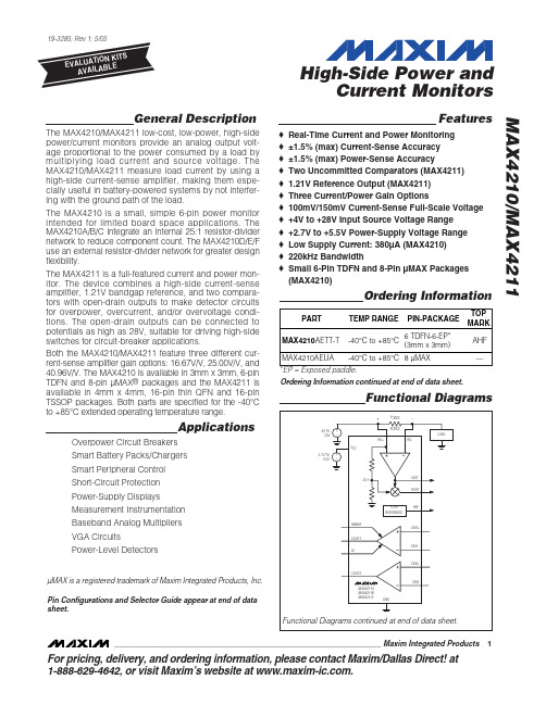
The MAX4210/MAX4211 low-cost, low-power, high-side power/current monitors provide an analog output voltage proportional to the power consumed by a load by multiplying load current and source voltage. The MAX4210/MAX4211 measure load current by using a high-side current-sense amplifier, making them especially useful in battery-powered systems by not interfering with the ground path of the load. The MAX4210 is a small, simple 6-pin power monitor intended for limited board space applications. The MAX4210A/B/C integrate an internal 25:1 resistor-divider network to reduce component count. The MAX4210D/E/F use an external resistor-divider network for greater design flexibility. The MAX4211 is a full-featured current and power monitor. The device combines a high-side current-sense amplifier, 1.21V bandgap reference, and two comparators with open-drain outputs to make detector circuits for overpower, overcurrent, and/or overvoltage conditions. The open-drain outputs can be connected to potentials as high as 28V, suitable for driving high-side switches for circuit-breaker applications. Both the MAX4210/MAX4211 feature three different current-sense amplifier gain options: 16.67V/V, 25.00V/V, and 40.96V/V. The MAX4210 is available in 3mm x 3mm, 6-pin TDFN and 8-pin µMAX® packages and the MAX4211 is available in 4mm x 4mm, 16-pin thin QFN and 16-pin TSSOP packages. Both parts are specified for the -40°C to +85°C extended operating temperature range.
max485esa中文资料
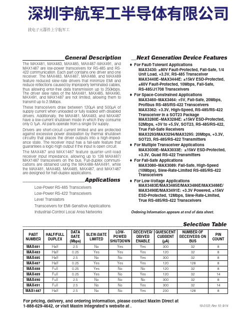
General DescriptionThe MAX481, MAX483, MAX485, MAX487–MAX491, andMAX1487 are low-power transceivers for RS-485 and RS-422 communication. Each part contains one driver and onereceiver. The MAX483, MAX487, MAX488, and MAX489feature reduced slew-rate drivers that minimize E MI andreduce reflections caused by improperly terminated cables,thus allowing error-free data transmission up to 250kbps.The driver slew rates of the MAX481, MAX485, MAX490,MAX491, and MAX1487 are not limited, allowing them totransmit up to 2.5Mbps.These transceivers draw between 120µA and 500µA ofsupply current when unloaded or fully loaded with disableddrivers. Additionally, the MAX481, MAX483, and MAX487have a low-current shutdown mode in which they consumeonly 0.1µA. All parts operate from a single 5V supply.Drivers are short-circuit current limited and are protectedagainst excessive power dissipation by thermal shutdowncircuitry that places the driver outputs into a high-imped-ance state. The receiver input has a fail-safe feature thatguarantees a logic-high output if the input is open circuit.The MAX487 and MAX1487 feature quarter-unit-loadreceiver input impedance, allowing up to 128 MAX487/MAX1487 transceivers on the bus. Full-duplex communi-cations are obtained using the MAX488–MAX491, whilethe MAX481, MAX483, MAX485, MAX487, and MAX1487are designed for half-duplex applications.________________________Applications Low-Power RS-485 Transceivers Low-Power RS-422 Transceivers Level Translators Transceivers for EMI-Sensitive Applications Industrial-Control Local Area Networks__Next Generation Device Features o For Fault-Tolerant Applications MAX3430: ±80V Fault-Protected, Fail-Safe, 1/4Unit Load, +3.3V, RS-485 Transceiver MAX3440E–MAX3444E: ±15kV ESD-Protected,±60V Fault-Protected, 10Mbps, Fail-Safe, RS-485/J1708 Transceivers o For Space-Constrained Applications MAX3460–MAX3464: +5V, Fail-Safe, 20Mbps,Profibus RS-485/RS-422 Transceivers MAX3362: +3.3V, High-Speed, RS-485/RS-422Transceiver in a SOT23 Package MAX3280E–MAX3284E: ±15kV ESD-Protected,52Mbps, +3V to +5.5V, SOT23, RS-485/RS-422,True Fail-Safe Receivers MAX3293/MAX3294/MAX3295: 20Mbps, +3.3V,SOT23, RS-485/RS-422 Transmitters o For Multiple Transceiver Applications MAX3030E–MAX3033E: ±15kV ESD-Protected,+3.3V, Quad RS-422 Transmitters o For Fail-Safe Applications MAX3080–MAX3089: Fail-Safe, High-Speed (10Mbps), Slew-Rate-Limited RS-485/RS-422Transceiverso For Low-Voltage ApplicationsMAX3483E/MAX3485E/MAX3486E/MAX3488E/MAX3490E/MAX3491E: +3.3V Powered, ±15kVESD-Protected, 12Mbps, Slew-Rate-Limited,True RS-485/RS-422 Transceivers For pricing, delivery, and ordering information, please contact Maxim Direct at1-888-629-4642, or visit Maxim Integrated’s website at .______________________________________________________________Selection Table19-0122; Rev 10; 9/14PARTNUMBERHALF/FULL DUPLEX DATA RATE (Mbps) SLEW-RATE LIMITED LOW-POWER SHUTDOWN RECEIVER/DRIVER ENABLE QUIESCENT CURRENT (μA) NUMBER OF RECEIVERS ON BUS PIN COUNT MAX481Half 2.5No Yes Yes 300328MAX483Half 0.25Yes Yes Yes 120328MAX485Half 2.5No No Yes 300328MAX487Half 0.25Yes Yes Yes 1201288MAX488Full 0.25Yes No No 120328MAX489Full 0.25Yes No Yes 1203214MAX490Full 2.5No No No 300328MAX491Full 2.5No No Yes 3003214MAX1487 Half 2.5No No Yes 2301288Ordering Information appears at end of data sheet.找电子元器件上宇航军工MAX481/MAX483/MAX485/MAX487–MAX491/MAX1487Low-Power, Slew-Rate-LimitedRS-485/RS-422 TransceiversPackage Information For the latest package outline information and land patterns, go to . Note that a “+”, “#”, or “-”in the package code indicates RoHS status only. Package drawings may show a different suffix character, but the drawing pertains to the package regardless of RoHS status.16Low-Power, Slew-Rate-Limited RS-485/RS-422 TransceiversMAX481/MAX483/MAX485/MAX487–MAX491/MAX1487Maxim Integrated cannot assume responsibility for use of any circuitry other than circuitry entirely embodied in a Maxim Integrated product. No circuit patent licenses are implied. Maxim Integrated reserves the right to change the circuitry and specifications without notice at any time. The parametric values (min and max limits) shown in the Electrical Characteristics table are guaranteed. Other parametric values quoted in this data sheet are provided for guidance.Maxim Integrated 160 Rio Robles, San Jose, CA 95134 USA 1-408-601-100017©2014 Maxim Integrated Products, Inc.Maxim Integrated and the Maxim Integrated logo are trademarks of Maxim Integrated Products, Inc.。
- 1、下载文档前请自行甄别文档内容的完整性,平台不提供额外的编辑、内容补充、找答案等附加服务。
- 2、"仅部分预览"的文档,不可在线预览部分如存在完整性等问题,可反馈申请退款(可完整预览的文档不适用该条件!)。
- 3、如文档侵犯您的权益,请联系客服反馈,我们会尽快为您处理(人工客服工作时间:9:00-18:30)。
Pin Configurations/Functional Diagrams/Truth Tables
TOP VIEW
IN1 COM1 NC1 VGND NC4 COM4 IN4 1 2 3 4 5 6 7 8 16 15 14 13 IN2 COM2 NC2 V+ N.C. NC3 COM3 IN3 IN1 COM1 NO1 VGND NO4 COM4 IN4 1 2 3 4 5 6 7 8 16 15 14 13 IN2 COM2 NO2 V+ N.C. NO3 COM3 IN3 IN1 COM1 NO1 VGND NO4 COM4 IN4 1 2 3 4 5 6 7 8 16 15 14 13 IN2 COM2 NC2
________________________________________________________________ Maxim Integrated Products 1
For free samples & the latest literature: , or phone 1-800-998-8800. For small orders, phone 1-800-835-8769.
元器件交易网
19-1391; Rev 0; 10/98
±15kV ESD-Protected, Quad, Low-Voltage, SPST Analog Switches
General Description
The MAX4551/MAX4552/MAX4553 are quad, low-voltage, single-pole/single-throw (SPST) analog switches. Each switch is protected against ±15kV electrostatic discharge (ESD) shocks, without latchup or damage. On-resistance (100Ω max) is matched between switches to 4Ω max, and is flat (8Ω max) over the specified signal range. Each switch can handle Rail-to-Rail® analog signals. The off-leakage current is only 1nA at +25°C and 10nA at +85°C. The MAX4551 has four normally closed (NC) switches, and the MAX4552 has four normally open (NO) switches. The MAX4553 has two NC and two NO switches. These CMOS switches can operate with dual power supplies ranging from ±2V to ±6V or a single supply between +2V and +12V. They are fully specified for single +2.7V operation. All digital inputs have +0.8V and +2.4V logic thresholds, ensuring TTL/CMOS-logic compatibility when using ±5V or a single +5V supply.
ELECTRICAL CHARACTERISTICS—Dual Supplies
(V+ = +5V, ±10%, V- = -5V, ±10%, TA = TMIN to TMAX, unless otherwise noted. Typical values are at TA = +25°C.) PARAMETER ANALOG SWITCH Analog Signal Range (Note 3) COM_ to NO_, COM_ to NC_ On-Resistance COM_ to NO_, COM_ to NC_ On-Resistance Match Between Channels (Note 4) COM_ to NO_, COM_ to NC_ On-Resistance Flatness (Note 5) NO_, NC_ Off-Leakage Current (Note 6) COM_ Off-Leakage Current (Note 6) COM_ On-Leakage Current (Note 6) VCOM_, VNO_, VNC_ RON ∆RON V+ = 5V, V- = -5V, VNO_ or VNC_ = ±3V, ICOM_ = 1mA V+ = 5V, V- = -5V, VNO_ or VNC_ = ±3V, ICOM_ = 1mA V+ = 5V, V- = -5V, VNO_ or VNC_ = +3V, 0, -3V V+ = 5.5V, V- = -5.5V, VCOM_ = 4.5V, VNO_ = ±4.5V C, E +25°C C, E +25°C C, E +25°C C, E +25°C C, E +25°C 4.5V C, E +25°C C, E -1 -10 -1 -10 -2 -20 0.01 0.01 0.01 4 1 V80 V+ 120 140 4 5 8 10 1 10 1 10 2 nA 20 Ω Ω V Ω SYMBOL CONDITIONS TA MIN TYP (Note 2) MAX ____________Features
o ±15kV ESD Protection per IEC 1000-4-2 o +2V to +12V Single Supply ±2V to ±6V Dual Supplies o 120Ω Signal Paths with ±5V Supplies o Low Power Consumption: <1µW o 4 Separately Controlled SPST Switches o Rail-to-Rail Signal Handling o Pin-Compatible with Industry-Standard DG211/DG212/DG213 o TTL/CMOS-Compatible Inputs with Dual ±5V or Single +5V Supply
Note 1: Signals on NC_, NO_, COM_, or IN_ exceeding V+ or V- are clamped by internal diodes. Limit forward-diode current to maximum current rating.
Stresses beyond those listed under “Absolute Maximum Ratings” may cause permanent damage to the device. These are stress ratings only, and functional operation of the device at these or any other conditions beyond those indicated in the operational sections of the specifications is not implied. Exposure to absolute maximum rating conditions for extended periods may affect device reliability.
________________________Applications
Battery-Operated Equipment Data Acquisition Test Equipment Avionics Audio Signal Routing Networking
Ordering Information continued at end of data sheet. *Contact factory for dice specifications.
元器件交易网
±15kV ESD-Protected, Quad, Low-Voltage, SPST Analog Switches MAX4551/MAX4552/MAX4553
ABSOLUTE MAXIMUM RATINGS
Voltages Referenced to GND V+.....................................................................-0.3V to +13.0V V- .....................................................................-13.0V to +0.3V V+ to V- ............................................................-0.3V to +13.0V All Other Pins (Note 1) ..........................(V- - 0.3V) to (V+ + 0.3V) Continuous Current into Any Terminal..............................±10mA Peak Current into Any Terminal (pulsed at 1ms,10% duty cycle)...................................±20mA ESD per Method 3015.7 (IN_, COM_, V+, V-, GND) .......>2500V IEC 1000-4-2 (NO_, NC_) ..................................................±15kV Continuous Power Dissipation (TA = +70°C) QSOP (derate 9.52mW/°C above +70°C) ....................762mW Narrow SO (derate 8.70mW/°C above +70°C) ............696mW Plastic DIP (derate 10.53mW/°C above +70°C) ..........842mW Operating Temperature Ranges MAX455_C_E ......................................................0°C to +70°C MAX455_E_E ...................................................-40°C to +85°C Storage Temperature Range .............................-65°C to +160°C Lead Temperature (soldering, 10sec) .............................+300°C