ES3A THRU ES3J SMB
机房和施工组织模板

江西新昌电厂“上大压小〞新建工程厂级管理信息系统〔MIS〕网络及硬件平台系统集成投标文件投标编号:03-ct-03-2007-156〔第三卷附件1-技术标准书〕投标人:安徽科大恒星电子商务技术二00九年四月目录第一章概述 (1)工程建设需求 (1)设计原那么 (2)实用性与先进性相结合 (2)可扩展性和开放性 (2)可靠性和平安性 (3)可管理性 (3)设计、施工标准 (3)工程建设目标 (6)第二章效劳器系统平台设计 (7)建设需求 (7)数据库效劳器设计 (7)IBM power550方案 (7)效劳器选型 (7)2.2.1.2 IBM Power 550配置 (12)HP 小型机方案 (13)效劳器选型 (13)2.2.2.2 HP Integrity rx6600 配置 (17)系统运行模式设计 (17)并行处理模式 (18)任务分担模式 (18)主机备用模式 (18)其它效劳器设计 (18)效劳器的部署 (18)物理效劳器与逻辑效劳器之间的关系 (19)效劳器选型设计 (20)2.3.3.1 IBM X3850 M2方案 (20)2.3.3.2 HP ProLiant DL580 G5 效劳器方案 (23)效劳器配置 (26)2.3.4.1 IBM X3850 M2配置 (26)2.3.4.2 HP ProLiant DL580 G5配置 (27)SAN存储系统设计 (27)2.4.1 IBM TotalStorage DS4800方案 (28)2.4.1.1 IBM TotalStorage DS4800介绍 (28)2.4.1.2 TotalStorage DS4800配置 (31)2.4.2 HP StorageWorks EVA8100方案 (32)2.4.2.1 HP StorageWorks EV A8100介绍 (32)2.4.2.2 HP StorageWorks EV A8100配置 (35)光纤交换机选型 (36)2.4.3.1 IBM System Storage SAN2005-B16 特性 (36)2.4.3.2 IBM System Storage SAN2005-B16 配置 (38)数据备份系统 (38)数据备份需求 (38)数据备份方案 (39)2.5.2.1 Veritas的优势 (39)2.5.2.2 Veritas配置 (42)磁带库选型配置 (43)虚拟磁带库选型 (44)第三章网络系统平台设计 (49)网络建设需求 (49)网络拓扑结构设计 (49)分层设计 (49)可靠性保证〔冗余设计〕 (49)网络拓扑实现 (50)核心层设计 (51)接入层设计 (51)远程访问层设计 (51)Cisco解决方案 (51)中心交换机选型 (51)3.3.1.1 Cisco® 6500介绍 (52)3.3.1.2 Supervisor Engine 720 (56)3.3.1.3 Cisco Catalyst 6513配置 (58)接入交换机选型 (59)H3C解决方案 (59)中心交换机选型 (59)H3C S7500E介绍 (60)H3C S7510E配置 (63)接入交换机选型 (63)第四章系统平安设计 (65)系统平安需求 (65)系统平安体系结构 (65)物理设备平安 (65)访问平安 (66)应用平安 (66)数据平安 (66)平安策略 (67)传输通道和传输设备平安 (67)应用平台平安 (68)资源访问平安 (68)网络防病毒 (69)多功能防火墙设计 (70)HillstoneSA-5020介绍 (71)HillstoneSA-5020功能规格 (72)内网核心平安防护系统〔主机加固〕设计 (74)S-NUMEN用途 (74)S-NUMEN功能 (75)S-NUMEN配置 (76)内网主机审计及监管系统 (76)系统功能 (77)系统特点 (79)体系架构 (80)配置 (81)防病毒系统设计 (81)网络防病毒配置 (84)第五章综合布线系统设计 (85)综合布线系统需求 (85)设计标准与设计目标 (85)设计标准 (85)设计目标 (86)布线系统设计 (86)光缆敷设 (86)SAN光纤走向 (86)布线系统测试 (87)测试标准与内容 (89)提交文档 (94)第六章工程组织与管理 (95)工程管理与目标 (95)工程组织及人力资源分配 (96)施工组织总体部署 (96)人力资源配置 (98)与相关单位合作 (99)与工程单位合作 (99)与厂商合作 (100)工程管理 (100)管理方法 (100)管理措施 (101)工程风险管理 (104)工程进度管理 (104)工程质量控制与保证 (105)工程阶段性评估 (106)第七章工程实施方案 (107)工程实施环节规划 (107)实施环节规划总表 (107)设计联络 (109)设备订货及到货 (110)实施现场情况调研 (110)制定详细实施方案 (111)培训 (111)设备验收 (111)查验设备 (111)查验方法 (112)查验报告 (117)系统安装调试 (117)系统调试方案制定 (117)小型机调试 (118)中心交换机调试 (118)边缘交换机调试 (118)中心路由器调试 (119)网管软件调试 (119)主机调试 (119)备份系统调试 (120)系统初验收 (120)试运行 (120)技术文档的提交 (121)系统终验 (121)技术支持与售后效劳 (121)实施进度方案 (121)里程碑事件及考核标准 (122)第八章验收方案与文档 (123)验收测试内容 (123)现场验收测试 (124)文档验收 (126)系统初验收 (126)系统终验 (127)测试方案 (127)测试方法 (127)测试工程 (127)测试方法 (128)工程文档 (129)工程文档内容 (129)工程文档提交方案 (132)第九章机房建设工程 (134)工程简述 (134)电子计算机机房组成及使用面积确定 (134)可维护性设备布置 (135)设计原那么 (135)计算机机房平安分类 (135)建设标准 (137)设计依据 (138)设计依据 (138)设计指标 (140)机柜及机房隔断、装饰设计 (141)机柜 (141)图腾机柜概述 (141)图腾机柜选型 (141)机房隔断 (141)装饰设计 (142)装修材料选材 (142)材料表 (143)吊顶 (143)地面 (144)墙、柱面 (145)门、窗 (145)供配电系统〔含UPS、照明等〕 (146)电气概述 (146)供配电系统 (147)设计标准要求 (147)9.5.2.2 机房配电冗余供电系统 (149)配电设备 (149)UPS系统 (149)UPS选型选型 (149)艾默生“UL33〞系列UPS性能参数 (150)美国“艾默生〞系列UPS特点 (151)电池配置 (151)照明系统设计 (152)普通照明系统设计 (153)应急照明、疏导灯具系统设计 (153)配电线路安装技术 (153)空调系统 (154)空调系统设计 (154)空调设备选型 (154)防雷接地 (154)防雷系统概述 (154)对雷电引入的分析 (155)机房防雷设计 (156)防雷验收及保障 (156)接地系统概述 (156)接地系统解决措施 (157)机房的地线系统 (157)局部等电位连接 (157)抗静电保护地 (157)静电防护 (158)KVM设备及机房布线 (158)KVM设计需求 (158)KVM设计方案说明 (159)环境监控、消防报警及其他相关效劳 (159)环境监控 (159)门禁系统 (159)视频监控 (159)动力环境监控 (159)消防报警 (160)9.9.3 控制台桌椅 (161)灾害处理 (161)机房区防水防护措施 (161)机房给水排水技术 (161)防虫、防鼠害 (162)电磁屏蔽 (162)第一章概述江西新昌电厂网络及硬件平台系统集成工程建设主要包括了网络系统、无线网络覆盖、效劳器系统、存储系统、数据备份系统、微软AD域设计及网络部署、管理及系统软件、MIS终端、智能机房、综合布线等系统,按现代先进技术设计,该系统集成完成后,新昌电厂具有统一的生产MIS系统运行平台,能为其信息化建设提供良好的根底效劳。
Motorola 3.5 kHz 产品说明书
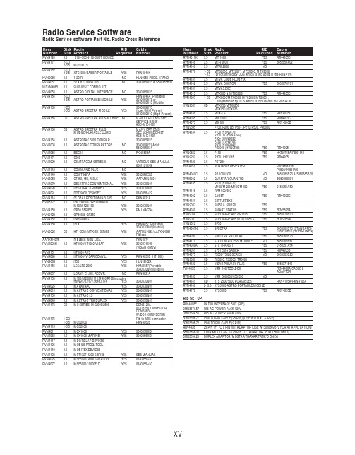
RVN4126 3.59100-386-9100-386/T DEVICERVN41772-CD2-3.5MCS/MTSRVN41821-CD2-3.5XTS3000/SABER PORTABLE YES RKN4046KHVN9085 3.51-20 R NO HLN9359 PROG. STAND RVN4057 3.532 X 8 CODEPLUG NO3080385B23 & 5880385B30 MDVN4965 3.59100-WS/T CONFIG KITRVN4053 3.5ASTRO DIGITAL INTERFACE NO3080385B23RVN41842-CD RKN4046A (Portable) 2-3.5ASTRO PORTABLE /MOBILE YES3080369B73 or0180300B10 (Mobile) RVN41831-CD3080369B732-3.5ASTRO SPECTRA MOBILE YES(Low / Mid Power)0180300B10 (High Power) RVN4185CD ASTRO SPECTRA PLUS MOBILE NO MANY OPTIONS; SEESERVICE BRIEF#SB-MO-0101RVN4186CD ASTRO SPECTRA PLUS MANY OPTIONS;MOBILE/PORTABLE COMB SEE SERVICE BRIEF#SB-MO-0101RVN4154 3.5ASTROTAC 3000 COMPAR.3080385B23RVN5003 3.5ASTROTAC COMPARATORS NO3080399E31 Adpt.5880385B34RVN4083 3.5BSC II NO FKN5836ARVN4171 3.5C200RVN4029 3.5CENTRACOM SERIES II NO VARIOUS-SEE MANUAL6881121E49RVN4112 3.5COMMAND PLUS NORVN4149 3.5COMTEGRA YES3082056X02HVN6053CD CT250, 450, 450LS YES AAPMKN4004RVN4079 3.5DESKTRAC CONVENTIONAL YES3080070N01RVN4093 3.5DESKTRAC TRUNKED YES3080070N01RVN4091 3.5DGT 9000 DESKSET YES0180358A22RVN4114 3.5GLOBAL POSITIONING SYS.NO RKN4021AHVN8177 3.5GM/GR300/GR500/GR400M10/M120/130YES3080070N01RVN4159 3.5GP60 SERIES YES PMLN4074AHVN9128 3.5GP300 & GP350RVN4152 3.5GP350 AVSRVN4150 3.5GTX YES HKN9857 (Portable)3080070N01(Mobile) HVN9025CD HT CDM/MTX/EX SERIES YES AARKN4083/AARKN4081RiblessAARKN4075RIBLESS NON-USA RKN4074RVN4098H 3.5HT1000/JT1000-VISAR YES3080371E46(VISAR CONV)RVN4151 3.5HT1000 AVSRVN4098 3.5HT1000/ VISAR CONV’L.YES RKN4035B (HT1000) HVN9084 3.5i750YES HLN-9102ARVN4156 3.5LCS/LTS 2000YES HKN9857(Portable)3080070N01(Mobile) RVN4087 3.5LORAN C LOC. RECV’R.NO RKN4021ARVN4135 3.5M100/M200,M110,M400,R100 includesHVN9173,9177,9646,9774YES3080070N01RVN4023 3.5MARATRAC YES3080070N01RVN4019 3.5MAXTRAC CONVENTIONAL YES3080070N01RVN4139 3.5MAXTRAC LS YES3080070N01RVN4043 3.5MAXTRAC TRK DUPLEX YES3080070N01RVN4178CD MC SERIES, MC2000/2500DDN6124AW/DB25 CONNECTORDDN6367AW/DB9 CONNECTOR RVN41751-CD Rib to MIC connector 1-3.5MCS2000 RKN4062BRVN41131-3.5MCS2000RVN4011 3.5MCX1000YES3000056M01RVN4063 3.5MCX1000 MARINE YES3000056M01RVN4117 3.5MDC/RDLAP DEVICESRVN4105 3.5MOBILE PROG. TOOLRVN4119 3.5MOBITEX DEVICESRVN4128 3.5MPT1327-1200 SERIES YES SEE MANUALRVN4025 3.5MSF5000/PURC/ANALOG YES0180355A30RVN4077 3.5MSF5000/10000FLD YES0180355A30RVN4017K 3.5MT 1000YES RTK4205CRVN4148 3.5MTR 2000YES3082056X02RVN4140 3.5MTRI 2000NORVN41761-CD MTS2000, MT2000*, MTX8000, MTX90001-3.5*programmed by DOS which is included in the RVN4176RVN4131 3.5MTVA CODE PLUG FIXRVN4142 3.5MTVA DOCTOR YES3080070N01RVN4131 3.5MTVA3.EXERVN4013 3.5MTX800 & MTX800S YES RTK4205CRVN4097 1-CD MTX8000/MTX9000,MTS2000,MT2000*,* programmed by DOS which is included in the RVN4176HVN9067CD MTX850/MTX8250MTX950,MTX925RVN4138 3.5MTX-LS YES RKN4035DRVN4035 3.5MX 1000YES RTK4203CRVN4073 3.5MX 800YES RKN4006BHVN9395 P100, P200 LB, P50+, P210, P500, PR3000RVN4134 3.5P100 (HVN9175)P200 LB (HVN9794)P50+ (HVN9395)P210 (HVN9763)P500 (HVN9941)PR3000 (HVN9586)YES RTK4205HVN9852 3.5P110YES HKN9755A/REX1143 HVN9262 3.5P200 UHF/VHF YES RTK4205RVN4129 3.5PDT220YVN4051 3.5PORTABLE REPEATER Portable rptr.P1820/P1821AXRVN4061C 3.5PP 1000/500NO3080385B23 & 5880385B30 RVN5002 3.5QUANTAR/QUANTRO NO3O80369E31RVN4135 3.5R100 (HVN9177)M100/M200/M110/M400YES0180358A52RVN4146 3.5RPM500/660RVN4002 3.5SABER YES RTK4203CRVN4131 3.5SETTLET.EXEHVN9007 3.5SM50 & SM120YESRVN4039 3.5SMART STATUS YES FKN5825AHVN9054 3.5SOFTWARE R03.2 P1225YES3080070N01HVN9001 3.5SOFTWARE R05.00.00 1225LS YES HLN9359AHVN9012 3.5SP50RVN4001N 3.5SPECTRA YES3080369B73 (STANDARD)0180300B10 (HIGH POWER) RVN4099 3.5SPECTRA RAILROAD YES3080369B73RVN4110 3.5STATION ACCESS MODULE NO3080369E31RVN4089A 3.5STX TRANSIT YES0180357A54RVN4051 3.5SYSTEMS SABER YES RTK4203BRVN4075 3.5T5600/T5620 SERIES NO3080385B23HVN9060CD TC3000, TS3000, TR3000RVN4123 3.5VISAR PRIVACY PLUS YES3080371E46FVN4333 3.5VRM 100 TOOLBOX FKN4486A CABLE &ADAPTORRVN4133 3.5VRM 500/600/650/850NORVN4181CD XTS 2500/5000 PORTABLES RKN4105A/RKN4106A RVN41002- 3.5XTS3000 ASTRO PORTABLE/MOBILERVN4170 3.5XTS3500YES RKN4035DRIB SET UPRLN4008E RADIO INTERFACE BOX (RIB)0180357A57RIB AC POWER PACK 120V0180358A56RIB AC POWER PACK 220V3080369B71IBM TO RIB CABLE (25 PIN) (USE WITH XT & PS2)3080369B72IBM TO RIB CABLE (9 PIN)RLN443825 PIN (F) TO 9 PIN (M) ADAPTOR (USE W/3080369B72 FOR AT APPLICATION) 5880385B308 PIN MODULAR TO 25 PIN ”D” ADAPTOR (FOR T5600 ONLY)0180359A29DUPLEX ADAPTOR (MOSTAR/TRAXAR TRNK’D ONLY)Item Disk Radio RIB Cable Number Size Product Required Number Item Disk Radio RIB Cable Number Size Product Required NumberUtilizing your personal computer, Radio Service Software (RSS)/Customer Programming Software (CPS)/CustomerConfiguration Software (CCS) enables you to add or reprogram features/parameters as your requirements change. RSS/CPS/CCS is compatible with IBM XT, AT, PS/2 models 30, 50, 60 and 80.Requires 640K RAM. DOS 3.1 or later. Consult the RSS users guide for the computer configuration and DOS requirements. (ForHT1000, MT/MTS2000, MTX838/8000/9000, Visar and some newer products —IBM model 386, 4 MEG RAM and DOS 5.0 or higher are recommended.) A Radio Interface Box (RIB) may be required as well as the appropriate cables. The RIB and cables must be ordered separately.Licensing:A license is required before a software (RVN) order is placed. The software license is site specific (customer number and ultimate destination tag). All sites/locations must purchase their own software.Be sure to place subsequent orders using the original customer number and ship-to-tag or other licensed sites; ordering software without a licensed customer number and ultimate tag may result in unnecessary delays. To obtain a no charge license agreement kit, order RPX4719. To place an order in the U.S. call 1-800-422-4210. Outside the U.S., FAX 847-576-3023.Subscription Program:The purchase of Radio ServiceSoftware/Customer Programming/Customer ConfigurationSoftware (RVN & HVN kits) entitles the buyer/subscriber to three years of free upgrades. At the end of these three years, the sub-scriber must purchase the same Radio Service Software kit to receive an additional three years of free upgrades. If the sub-scriber does not elect to purchase the same Radio Service Software kit, no upgrades will be sent. Annually a subscription status report is mailed to inform subscribers of the RSS/CPS/CCS items on our database and their expiration dates.Notes:1)A subscription service is offered on “RVN”-Radio Service Software/Customer Programming/Customer Configuration Software kits only.2)“RVN” software must only be procured through Radio Products and Services Division (RPSD). Software not procured through the RPSD will not be recorded on the subscription database; upgrades will not be mailed.3)Upgrades are mailed to the original buyer (customer number & ultimate tag).4)SP software is available through the radio product groups.The Motorola General Radio Service Software Agreement is now available on Motorola Online. If you need assistance please feel free to submit a “Contact Us” or call 800-422-4210.SMART RIB SET UPRLN1015D SMART RIB0180302E27 AC POWER PACK 120V 2580373E86 AC POWER PACK 220V3080390B49SMARTRIB CABLE (9 PIN (F) TO 9 PIN (M) (USE WITH AT)3080390B48SMARTRIB CABLE (25 PIN (F) TO 9 PIN (M) (USE WITH XT)RLN4488ASMART RIB BATTERY PACKWIRELESS DATA GROUP PRODUTS SOFTWARERVN4126 3.59100-386/9100T DEVICES MDVN4965 3.59100-WS/T CONFIG’TN RVN41173.5MDC/RDLAP DEVICESPAGING PRODUCTS MANUALS6881011B54 3.5ADVISOR6881029B90 3.5ADVISOR ELITE 6881023B20 3.5ADVISOR GOLD 6881020B35 3.5ADVISOR PRO FLX 6881032B30 3.5BR8506881032B30 3.5LS3506881032B30 3.5LS5506881032B30 3.5LS7506881033B10 3.5LS9506881035B20 3.5MINITOR III8262947A15 3.5PAGEWRITER 20008262947A15 3.5PAGEWRITER 2000X 6881028B10 3.5TALKABOUT T3406881029B35 3.5TIMEPORT P7308262947A15 3.5TIMEPORT P930NLN3548BUNIVERSAL INTERFACE KITItem Disk Radio NumberSize Product。
Ruilong SMBJ6.8A CA 过流保护器说明书
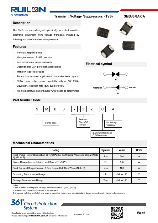
DescriptionThe SMBJ series is designed specifically to protect sensitive electronic equipment from voltage transients induced by lightning and other transient voltage events.Featuresl Very fast response timel Halogen free and RoHS compliant l Low incremental surge resistance l Optimized for LAN protection applications l Matte tin lead –free Platedl For surface mounted applications to optimize board space l 600W peak pulse power capability with at 10/1000μswaveform, repetition rate (duty cycle): 0.01%l High temperature soldering:260°C/10 seconds at terminalsElectrical symbolPart Number CodeMechanical CharacteristicsRating SymbolValueUnits Peak Pulse Power Dissipation at T A =25ºC by 10/1000μs Waveform (Fig.2)(Note 1), (Note 2)P PP600WPower Dissipation on Infinite Heat Sink at T L =50°CP D 5.0 WPeak Forward Surge Current, 8.3ms Single Half Sine Wave (Note 3) I FSM 100A Operating Temperature Range T J -55 to 150 °C Storage Temperature RangeT STG-55 to 150°CNotes:1. Non-repetitive current pulse, per Fig.4 and derated above T A =25ºC per Fig. 3.2. Mounted on 5.0x5.0mm copper pad to each terminal.3. Measured on 8.3ms single half sine wave or equivalent square wave for unidirectional device only, duty cycle=4 per minute maximum.CathodeBIUNIAnodeElectrical CharacteristicsType Number MarkingReverse Stand-Off Voltage Breakdown Voltage Test Current Max. Clamping Voltage Max.Peak PulseCurrent ReverseLeakageV RWMV BR @I T I T V C @I PP I PP I R @V RWM Min Max UNI BI UNI BI V V V mA V A µA SMBJ6.8ASMBJ6.8CA6.8A6.8CA5.86.457.141010.557.01000Notes: For bidirectional type having V R of 10V and less, the I R limit is double.I-V Curve CharacteristicsP PPM Peak Pulse Power Dissipation -- Max power dissipationV R Stand-off Voltage -- Maximum voltage that can be applied to the TVS without operationV BR Breakdown Voltage -- Maximum voltage that flows though the TVS at a specified test current (I T )V C Clamping Voltage -- Peak voltage measured across the TVS at a specified Ippm (peak impulse current) I R Reverse Leakage Current -- Current measured at V R V F Forward Voltage Drop for Uni-directionalRatings and Characteristic Curves (T A =25°C unless otherwise noted) Figure 1 - TVS Transients Clamping WaveformFigure 2 - Peak Pulse Power Rating CurveFigure 3 - Pulse Derating Curve Figure 4 - Pulse WaveformFigure 5 - Typical Junction CapacitanceFigure 6 - Steady State Power Derating CurveFigure 7 - Maximum Non-Repetitive Surge CurrentSoldering Parameters - Reflow Soldering (Surface Mount Devices)Reflow ConditionPb - Free assembly Pre Heat-Temperature Min (T s(min))150°C -Temperature Max (T s(max)) 200°C- Time (min to max) (t s )60 -180 Seconds Average ramp up rate ( Liquids Temp T L ) to peak3°C/second maxT S(max) to TL - Ramp-up Rate 3°C/second max Reflo w- Temperature (T L ) (Liquids)217°C- Time (min to max) (t s )60 -150 Seconds Peak Temperature (T P ) 260 +0/-5°C Time within 5°C of actual peak Temperature (t p ) 20 - 40 Seconds Ramp-down Rate6°C/second max Time 25°C to peak Temperature (T P ) 8 minutes MaxDo not exceed260°CPart Marking SystemDimensionsDIMMillimeters InchesMinMax MinMax A 1.95 2.20 0.077 0.086 B 4.06 4.57 0.160 0.180 C 3.30 3.94 0.130 0.155 D 2.13 2.44 0.084 0.096 E 0.76 1.52 0.030 0.060 G 5.11 5.49 0.201 0.216 I 2.26 - 0.089 - J 2.16 - 0.085 - K -2.74 -0.107 L 2.16 - 0.085-T PT L T S(max)T S(min)25T e m p e r a t u r efor Uni-directional products only )Marking codeTaping and Reel SpecificationsSymbol Millimeters Inches W 12±0.3 0.472±0.012 P 8±0.1 0.315±0.004 F 5.5±0.1 0.217±0.004 E 1.75±0.1 0.069±0.004 D 1.5+0.1/-0.0 0.059+0.004/-0.0 P0 4±0.1 0.157±0.004 P2 2±0.1 0.079±0.004 D0 16.7±0.15 0.657±0.006 D1 178±2 7.007±0.079D2 59.6+1/-2 2.346+0.039/-0.079W1 12.64±0.40.498±0.016Part NumberComponent packageQuantityPackaging optionPackaging specificationSMBJ6.8A/CADO-214AA500Tape&Reel-12mm/7”tapeEIA STD RS-481。
sangfor ngaf m5150-f-i datasheet说明书
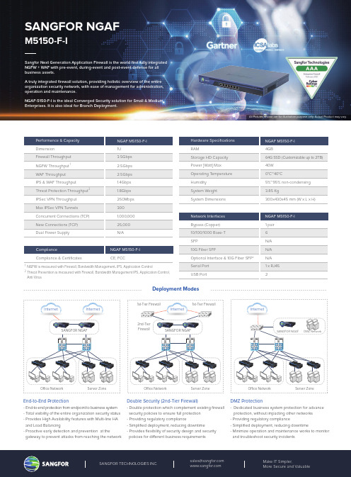
Performance & Capacity NGAF M5150-F-I DimensionIPSec VPN Throughput Max IPSec VPN Tunnels Concurrent Connections (TCP)New Connections (TCP)Dual Power Supply1U 250Mbps 3001,000,00025,000N/AHardware Specifications RAMStorage HD Capacity Power [Watt] Max Operating T emperature Humidity System Weight System DimensionsNGAF M5150-F-I 4GB64G SSD (Customizable up to 2TB)40W 0°C~40°C5%~95% non-condensing 3.85 Kg300x430x45 mm (W x L x H)Network Interfaces Bypass (Copper)10/100/1000 Base-T SFP10G Fiber SFPOptional Interface & 10G Fiber SFP*Serial Port USB PortNGAF M5150-F-I 1 pair 6N/A N/A N/A 1 x RJ452End-to-End Protection - End-to-end protection from endpoint to business system- T otal visibility of the entire organization security status- Provides High Availability features with Multi-line HA and Load Balancing- Proactive early detection and prevention at thegateway to prevent attacks from reaching the network Double Security (2nd-Tier Firewall)- Double protection which complement existing firewall security policies to ensure full protection - Providing regulatory compliance- Simplified deployment, reducing downtime - Provides flexibility of security design and security policies for di erent business requirementsDMZ Protection- Dedicated business system protection for advance protection, without impacting other networks - Providing regulatory compliance- Simplified deployment, reducing downtime- Minimize operation and maintenance works to monitor and troubleshoot security incidentsInternet O ce Network SANGFOR NGAFServer Zone O ce Network Server Zone Internet Internet SANGFOR NGAF1st-Tier Firewall1st-Tier FirewallComplianceCompliance & CertificatesNGAF M5150-F-I CE, FCCDeployment ModesSANGFOR NGAFM5150-F-ISangfor Next Generation Application Firewall is the world first fully integrated NGFW + WAF with pre-event, during-event and post-event defense for all business assets.A truly integrated firewall solution, providing holistic overview of the entire organization security network, with ease of management for administration, operation and maintenance.NGAF-5150-F-I is the ideal Converged Security solution for Small & Medium Enterprises. It is also ideal for Branch Deployment.2nd-Tier FirewallO ce Network Server ZoneInternetSANGFOR NGAF DMZ NetworkNGFW is measured with Firewall, Bandwidth Management , IPS, Application ControlThreat Prevention is measured with Firewall, Bandwidth Management IPS, Application Control, Anti Virus12Firewall Throughput IPS & WAF Throughput NGFW Throughput WAF Throughput 3.5Gbps Threat Protection Throughput 1.8Gbps 1.4Gbps 2.5Gbps 2.5Gbps 12All Pictures shown are for illustration purpose only. Actual Product may vary.Hardware Description1. Management Console2. USB ports3. Default Interface4. Line Interface5. Power outlet6. Switch7. Fan Trays8. LED IndicatorsAll Pictures shown are for illustration purpose only. Actual Product may vary.13824765Software FeaturesNetworkingInterface: Physical Interface, Sub Interface, VLAN Interface, Aggregated InterfaceRouting: Static, Policy-based, RIP, OSPF, BGPNetwork Functions: ARP, DNS, DHCP, SNMP, NAT, High Availability01Access ControlUser: Import / export from external server Authentication: SSO/LDAP/RADIUS Application: ACL and application rules URL Filter: Supported02VPNSANGFOR VPN, IPSEC VPN and SSL VPN supported SDWAN auto path selection03ManagementSNMP v1, v2c, v3SyslogReal-Time Vulnerability Scanner Central management04Key FeaturesFully converged security solution from endpoint to business systems, without the needs of manual integration & consolidation of each feature, as well as additional hardware, which results in lower operational and maintenance costs.Lower TCO Converged Security SolutionsComprehensive business systems protection with built-in Web Application Firewall and Vulnerability Scanners, which is critical for internal systems as well as "internet-facing" systems. Business systems protection is easily enabled via advanced license, without any integration or additional appliance required.Comprehensive Business Systems ProtectionA single simplified operation & maintenance with interactive GUI, which provides ease of configuration, maintenance, troubleshooting and reporting for IT managers, administrators and operations team.User Friendly12Integrated L2–L7 Security features:DoS/DDoS: Inbound, Outbound, Attack Protection Content Security IPS Anti-virusEngine Zero: AI based anti-malware, anti-virus APT WAFData Leakage Prevention Bandwidth Management Web ScannerReal-Time Vulnerability Scanner Security ReporterNeural-X: Cloud threat intelligence and analyticsWeb Application Firewall (WAF) Semantic EngineSupport OWASP Top 10 WAFrequirementsRecommended by NSSSecurity FeaturesConverged SecurityComprehensive WAF123NGAF_DS_P_NGAF515-Datasheet_20210315For more information on Sangfor' full range of support & services, please contact your local representative.NGAF M5150-F-I Ordering Guide* All bundles are o ered in 1, 2, 3 or 5 year incrementsESS-M515-1/2/3/5Y PM-M515-1/2/3/5Y ULT-M515-1/2/3/5YSKUSKUDescriptionM5150-F-I, Essential Bundle (FW, BM, URL filtering, Application Control, IPS, Email Security, Risk Assessment, Security Visibility, Basic Security Reporter)M5150-F-I, Premium Bundle Including Essential Subscription & Engine Zero & Neural-XM5150-F-I, Ultimate Bundle including Premium Subscription & Platform-X (NGAF & Endpoint Secure Management, Event Correlation & Response, Security Posture Reporting) &Incident Response (2 times per annum) & Complimentary 30 units of Endpoint Secure Protect Agents (Limited Time O er)“A La Carte” Subscription LicenseFNX-M515-1/2/3/5Y FEZ-M515-1/2/3/5Y WAFL-M515-1/2/3/5YDescriptionM5150-F-I, Neural-X License, Threat Intelligence & Analytics, Unknown Threat & Advanced Threat Defense, Value-Added Cloud Service M5150-F-I, Engine Zero License, AI powered Malware Detection, Anti-malware, Anti-virusM5150-F-I, Add Anti-Defacement Module, Web Application FW, Application Hiding, HTTP Anomalies Detection, Data Leak Protection, Web Scanner, Vulnerability Scanner,Advanced Security ReporterSKUHardware Support ServicesSTS-M515-1/2/3/5Y HRTF-M515-1/2/3/5Y HSDS-M515-1/2/3/5Y HNBD-M515-1/2/3/5Y H244G-M515-1/2/3/5YDescriptionM5150-F-I, NGAF Software Upgrade, 24*7 Technical Support Services M5150-F-I, NGAF,Return to Factory (5 Business days ship after receipt)M5150-F-I, NGAF, SDS Hardware Service M5150-F-I, NGAF, NBD Hardware Service M5150-F-I, 24x7x4 Delivery Hardware Service。
KDS USB FW Update User Manual
111-38-URM-011KDS USB FW UpdateUser ManualKDS USB FW Update 111-38-URM-011Table of Contents1. Introduction (3)2. Process under Microsoft Windows (4)3. Process under Mac OS (5)KDS USB FW Update 111-38-URM-0111. IntroductionThe Epson Kitchen Display System (henceforth KDS) is preferably updated using the KDS Utility. However, an alternate update method using a USB flash drive can be employed as fallback if required, and is typically faster than with the KDS Utility, albeit at the cost of losing any configuration from the KDs device. This document describes the typical process to set up a USB flash drive for the firmware update.The same firmware update process is used for printers and controllers (henceforth called display box). Once set up, the USB flash drive can be used to sequentially update multiple devices.IMPORTANT NOTES:i. Before you proceed, note that updating the KDS using this method erases allconfiguration from the target device(s). The KDS Utility may be used to re-configure the system.ii. There are certain flash drives that may not work with this method and would fail the update process verification step in the procedures. Some models tested include:a. Kingston DataTraveler 8GB/16GBb. Transcend JetFlash V70 16GBc. Axiom Stealth 2 USBFD2 2GBd. SanDisk Cruzer Dial USB 16GBe. Misc. brands like AData, Samsung, Verbatim, Sony etc. USB 2.0 flash drivesKDS USB FW Update 111-38-URM-0112. Process under Microsoft WindowsThe following process has been verified under Microsoft Windows 7 and Windows 10. Most failures with the method can be attributed to user permissions (inability to modify USB flash drive) incompatible or corrupted USB flash drives.Here are the basic instructions for flashing the printer/display box FW:1. Get a USB flash drive of 1GB or more with no contents you care about, as everything on it will beerased.2. Plug the USB flash drive into a Windows PC.3. Run dd_win.exe (provided in the firmware update package)o Click on “File select…” and browse to the file “usb_boot_image_v26.ubi”o Click on “Drive select…” and specify the drive letter of the USB sticko Hit 'Run' and wait until completed.4. ***IMPORTANT*** Safely eject the USB flash drive from Windows, then unplug it, wait a fewseconds, then plug it back in again.5. Unzip the “KDS Image.zip” file onto the USB flash drive. The final layout of the USB stick should be:\|- autooperation|- uImage|- BOOT.BIN|- images\|-- control.tar.gz|-- hibdrv|-- hibernation|-- hibernationinfo|-- rootfs|-- uImage|-- writable-region6. Eject the USB stick from the PC again.7. Label the USB stick with ‘KDS Image’ to indicate what image is on it in case it is requ ired for otherdisplay boxes/printers or in future.Follow these instructions for each printer/display box that needs to be updated:1. With the printer/display box turned off, plug the USB flash drive into the Interface card at the back.2. Use a pen or paper clip to press the button on the BACK of the printer/display box, and keep itpressed while turning the board on. Keep holding the button down for three or four seconds until the LED near the button goes out.3. The LED light will then show orange for about 45 seconds, and then green for about 5 seconds, thenflash orange for about 60 seconds. Once the FW update is complete, the LED will flash green.4. Turn off the printer.5. Remove the USB flash drive from the back.6. Turn the printer/display box back on and wait for it to boot up; the LED on the back turns solid green.The KDS splash screen will show the new FW version on the attached monitor.7. The system should be ready to go.KDS USB FW Update 111-38-URM-0113. Process under Mac OSThe following process has been verified under Mac OS 10 and 11. Most failures with the method can be attributed to user permissions (inability to modify USB flash drive) incompatible or corrupted USB flash drives.Here are the basic instructions for flashing the printer/display box FW:1. Save the firmware update package (which includes the file usb_boot_image_v26.ubi) in the Desktopor Downloads folder.2. Get a USB flash drive of 1GB or more with no contents you care about, as everything on it will beerased. Do NOT plug it in yet.3. On the Mac, open a new terminal (iTerm).4. Type the command “diskutil list”to get the current list of devices.5. Now plug the USB flash drive into the Mac.6. Type the command “diskutil list”again and note the additional device, which is the USB flashdrive (e.g. /dev/disk2).7. Type the command “diskutil unmountDisk /dev/diskX”, where X is the number from Step 5.8. Type the following command:sudo dd if=$(find ~ -name usb_boot_image_v26.ubi | head -n 1) of=/dev/diskX bs=1m(again, substitute the X in the command with the number you learned from Step 5.)Please note:i. The command above will ask for the user (or administrator) password once; this is normal.ii. The command, when run for the first time, will trigger several pop-up dialogs requesting access to some folders. See Figure 3.1.iii. The command will output several lines with the text “Operation not permitted” when trying to search certain inaccessible folders; this is normal.Figure 3.1: Mac OS pop-ups requesting user permission to access some folders.(c ontinued…)KDS USB FW Update 111-38-URM-0119. ***IMPORTANT*** Safely eject the USB stick from the Mac, then unplug it, wait a fewseconds, then plug it back in again.10. Unzip the KDS Image.zip file into USB stick. This means the final layout for the USB stick should be:\|- autooperation|- uImage|- BOOT.BIN|- images\|-- control.tar.gz|-- hibdrv|-- hibernation|-- hibernationinfo|-- rootfs|-- uImage|-- writable-region11. Eject the USB stick from the Mac again.12. Label the USB stick with ‘KDS Image’ to indicate what image is on it in case it is required for otherdisplay boxes/printers or in future.Follow these instructions for each printer/display box that needs to be updated:1. With the printer/display box turned off, plug the USB flash drive into the Interface card at the back.2. Use a pen or paper clip to press the button on the BACK of the printer/display box, and keep itpressed while turning the board on. Keep holding the button down for three or four seconds until the LED near the button goes out.3. The LED light will then show orange for about 45 seconds, and then green for about 5 seconds, thenflash orange for about 60 seconds. Once the FW update is complete, the LED will flash green.4. Turn off the printer.5. Remove the USB flash drive from the back.6. Turn the printer/display box back on and wait for it to boot up; the LED on the back turns solid green.The KDS splash screen will show the new FW version on the attached monitor.7. The system should be ready to go.KDS USB FW Update 111-38-URM-011This page intentionally left blank.KDS USB FW Update 111-38-URM-011。
数据中心-设备清单

5年 5年 5年 5年 5年
5年
集成商代表签字:
盖章:
年月日
项目组代表签字: 年月日
硬件组代表签字: 年月日
最终用户代表签字: 年月
盖章: 日
12
SFP-GE-SX-MM850D
光模块-SFP-GE-多 24 模模块-
(850nm,0.55km,LC)
13
LS-5500-52C-EI
SC3 H3C 5552
主机,配置普通引
擎后自带2个千兆光
电复用Combo口
17
(电口十百千兆自 RT-MSR5040-AC-H3 1 适应),4个SIC槽
位,4个FIC槽位,2
个ESM槽位,1个
VCPM槽位,4个
VPM槽位,1块交流
电源;
集成商代表签字:
年月日
RA3
H3C MSR50
盖章:
项目组代表签字: 年月日
5年
5年 数据 接入
盖章: 日
接口模块(SFP,LC)
光模块-SFP-GE-多
48 模模块-
(850nm,0.55km,LC)
1
H3C S7503E 以太网 交换机主机
H3C S7502E 交流电
2 源模块,650W+适配
器 H3C S7500E
2 Salience VI交换路由
引擎 H3C
S7500E
4Байду номын сангаас端口
1 千兆以太网电接口
H3C S5500-52C-EI以太网交换机主机 (48个 10 10/100/1000BaseT+4个 100/1000Base-X
Combo+2Slots)
VAR-SOM-MX8M-PLUS based on NXP i.MX 8M Plus Evalua

VAR-SOM-MX8M-PLUS based on NXP i.MX 8M PlusEvaluation Kit Quick Start GuideFeatures:1. Power ON Switch (SW7)2. 12V DC In Jack (J24)3. USB Debug (J29)4. micro SD Card slot (J28)5. USB 3.0 OTG (J26)6. USB 2.0 Host (J23)7. Gigabit Ethernet #0 (J21) 8. Gigabit Ethernet #1 (J20)9. MIPI-CSI #1 Camera connector [optional] (J19) 10. Miscellaneous Header #1 (J17)11. HDMI/ MIPI-CSI #2 Camera connector[optional] (J13)12. Mini PCI Express Connector (J15) 13. Miscellaneous Header #2 (J3) 14. SOM Connector (J1) 15. LVDS#B Header (J5)16. LVDS#A/ DSI Header (J7) 17. Fan Power Connector (J9) 18. Digital Microphone (U1) 19. Resistive Touch (J10) 20. Capacitive Touch (J11)21. User Buttons (SW1, SW2, SW4) 22. Line-In Connector (J12)23. Headphones Connector (J14) 24. Boot Select Switch (SW3)25. SAI/I2C/SPI/CAN Header (J16) 26. Reset Button (SW5)27. PWR Select Switch (SW6) 28. UART/PWM Header (J18) 29. RTC Battery Holder (JBT1)Evaluation kit initial Setup1. Carefully remove the 7” LCD and Symphony-Board from the package.2. Connect the 7” LCD Display and Touch cablesto the Evaluation Kit connectors J7, J11 respectively.Note:connect the display cable with the red wire on pin 1. Connect the touch cable with the metal contacts facing down.3. Plug the USB type A to micro B cable betweenthe USB debug connector (J29) and a PC USB port.4. For heatsink assembly instructions, pleasefollow the VHP-VS8M documentation .Please note that the heatsink is mainly used for CPU/GPU intensive applications and may be required per your specific use case.P/N VSS0177AVAR-SOM-MX8M-PLUS based on NXP i.MX 8M PlusEvaluation Kit Quick Start GuideSetting the host PC for debug1. Download any PC terminal software (e.g. Putty ).2. Set the PC terminal software parameters as follows:- Baud Rate: 115200 - Data bits: 8 - Stop bits: 1 - Parity: None- Flow Control: NoneBooting from eMMC1. Set Boot select switch (SW3) to “Internal” position to boot from the VAR-SOM-MX8M-PLUS internal storage.2. Plug the wall adapter into the 12V power jack (J24) and to a 120VAC~240VAC power source.3. Set Power ON switch (SW7) to ON state.4. Boot messages are printed within the PC terminal window.Booting from a micro SD cardThe microSD card is supplied within the package. Updated SD card images can also be downloaded from the Variscite FTP server.See more details in the recovery SD card section in the Variscite Wiki pages.1. Set Power ON switch (SW7) to off state.2. Set Boot select switch (SW3) to “SD ” positionin order to boot from SD Card.3. Push microSD card into the microSD cardslot (J28) of the Symphony-Board.4. Set Power ON switch (SW7) to ON state.5. Boot messages are print ed within PC’sterminal window.(Re-)Installing the file system to eMMCPlease refer to the recovery SD card section in the Variscite Wiki pages.Linkso Wiki page:https:///index.php?title=VAR-SOM-MX8M-PLUSo VAR-SOM-MX8M-PLUS Evaluation kits:https:///product/evaluation-kits/var-som-mx8m-plus-evaluation-kits/o VAR-SOM-MX8M-PLUS System on Module:https:///product/system-on-module-som/cortex-a53-krait/var-som-mx8m-plus-nxp-i-mx-8m-plus/o Symphony carrier board:https:///product/single-board-computers/symphony-board/o Customer portal:https:///loginThank you for purchasing Variscite’s product.For additional assistance please contact: *******************。
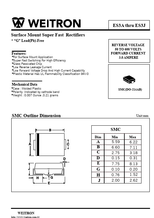
ES3J中文资料
.01 0 0.2 0.4 0.6 0.8 1.0 1.2 1.4 1.6 1.8
0.1 0 20 40 60 80 100 120 140
INSTANTANEOUS F ORWARD VOLTAGE, VOLTS
PERCENT OF RATED PEAK REVERSE VOL TAGE, (%)
1000
FIG.4 - TYPICAL REVERS E CHARACTERISTICS
INS TANTANEOUS REVERSE CURRENT, (uA)
TJ = 125 C
ES3A-ES3D
ES3G ES3J
100
1.0
10
0.1
1.0
TJ = 2 C 5
TJ = 25 C PULSEWIDTH:300us
*For Surface Mount Application *Super Fast Switching For High Efficiency *Glass Passivated Chip *Low Reverse Leakage Current *Low Forward Voltage Drop And High Current Capability *Plastic Meterial Has UL Flammability Classification 94V-0
20
40
60
80
100
120
140
160
1
2
5
10
20
50
100
LEAD TEMPERATURE , C
NUMBER OF CYCLES AT 60Hz
FIG.3 - TYPICAL FORWARD CHARACTERIS TICS
- 1、下载文档前请自行甄别文档内容的完整性,平台不提供额外的编辑、内容补充、找答案等附加服务。
- 2、"仅部分预览"的文档,不可在线预览部分如存在完整性等问题,可反馈申请退款(可完整预览的文档不适用该条件!)。
- 3、如文档侵犯您的权益,请联系客服反馈,我们会尽快为您处理(人工客服工作时间:9:00-18:30)。
UNITS VOLTS VOLTS VOLTS
Amps
Amps
Volts µA ns pF C/W C
MDD ELECTRONIC
AVERAGE FORWARD RECTIFIED CURRENT, AMPERES
INSTANTANEOUS FORWARD CURRENT,AMPERES
RATINGS AND CHARACTERISTIC CURVES ES3A THRU ES3J
MAXIMUM RATINGS AND ELECTRICAL CHARACTERISTICS
Ratings at 25 C ambient temperature unless otherwise specified. Single phase half-wave 60Hz,resistive or inductive load,for capacitive load current derate by 20%.
FIG. 2-MAXIMUM NON-REPETITIVE PEAK FORWARD SURGE CURRENT
100
80
60
40
20
8.3ms SINGLE HALF SINE-WAVE
(JEDEC Method)
0
1
10
100
NUMBER OF CYCLES AT 60 Hz
FIG. 4-TYPICAL REVERU ES3J
DO-214AA/SMB
0.087 (2.20) 0.071 (1.80)
0.096(2.44) 0.084(2.13)
0.180(4.57) 0.160(4.06)
SURFACE MOUNT SUPER FAST RECTIFIER
Reverse Voltage - 50 to 600 Volts Forward Current - 3.0 Amperes
MDD Catalog Number
SYMBOLS ES3A ES3B ES3C ES3D ES3E ES3G ES3J
Maximum repetitive peak reverse voltage Maximum RMS voltage Maximum DC blocking voltage Maximum average forward rectified current at TL=75 C Peak forward surge current 8.3ms single half sine-wave superimposed on rated load (JEDEC Method) Maximum instantaneous forward voltage at 3.0A Maximum DC reverse current TA=25 C at rated DC blocking voltage TA=100 C Maximum reverse recovery time (NOTE 1) Typical junction capacitance (NOTE 2) Typical thermal resistance (NOTE 3) Operating junction and storage temperature range
VRRM VRMS VDC
I(AV)
50 100 150 200 300 400 600 35 70 105 140 210 280 420 50 100 150 200 300 400 600
3.0
IFSM
VF
IR trr CJ RθJA TJ,TSTG
100.0
0.95
1.25
1.7
5.0 100.0
1,000
100
10 TJ=100 C
1
TJ=25 C 0.1
0.01 0
20
40
60
80
100
PERCENTAGE OF PEAK REVERSE VOLTAGE,%
FIG. 6-TYPICAL TRANSIENT THERMAL IMPEDANCE
100
10
1
0.1
0.01
0.1
1
10
100
t,PULSE DURATION,sec.
200
100
10
TJ=25 C
1
0.1
1.0
10
100
REVERSE VOLTAGE,VOLTS
TRANSIENT THERMAL IMPEDANCE, C/W
INSTANTANEOUS REVERSE CURRENT, MICROAMPERES
PEAK FORWARD SURGE CURRENT, AMPERES
0.155(3.94) 0.130(3.30)
0.012(0.305) 0.006(0.152)
FEATURES
The plastic package carries Underwriters Laboratory Flammability Classification 94V-0 For surface mounted applications Low reverse leakage Built-in strain relief,ideal for automated placement High forward surge current capability High temperature soldering guaranteed: 250 C/10 seconds at terminals Glass passivated chip junction
MECHANICAL DATA
0.060(1.52) 0.030(0.76)
0.008(0.203)MAX.
0.220(5.59) 0.205(5.21)
Dimensions in inches and (millimeters)
Case: JEDEC DO-214AA molded plastic body Terminals: leads solderable per MIL-STD-750, Method 2026 Polarity: Color band denotes cathode end Mounting Position: Any Weight:0.003 ounce, 0.093 grams
JUNCTION CAPACITANCE, pF
MDD ELECTRONIC
FIG. 1- FORWARD CURRENT DERATING CURVE
3.0
2.4
1.8
1.2
Single Phase
Half Wave 60Hz
Resistive or
inductive Load
0.6
0
0
25
50
75
100 125 150
175
AMBIENT TEMPERATURE, C
FIG. 3-TYPICAL INSTANTANEOUS FORWARD CHARACTERISTICS
35
45.0 47.0
-50 to +150
Note:1.Reverse recovery condition IF=0.5A,IR=1.0A,Irr=0.25A 2.Measured at 1MHz and applied reverse voltage of 4.0V D.C.
3.P.C.B. mounted with 0.2x0.2”(5.0x5.0mm) copper pad areas
20
10
TJ=25 C PULSE WIDTH=300 µs
1%DUTY CYCLE
1
0.1
0.01 0
0.4
0.8
ES3A-ES3D ES3E-ES3G ES3J
1.2
1.6 1.8
INSTANTANEOUS FORWARD VOLTAGE, VOLTS
FIG. 5-TYPICAL JUNCTION CAPACITANCE