Character Setup9
成立的英文setup例句

成立的英文set up例句我们都学过成立的英文,可是很多人只知道成立的英文是set up,其实成立的英文还有establish。
下面是店铺为你整理的成立的英文,希望大家喜欢!成立的英文1.set up2.establishset up例句1. The security zone was set up to prevent guerrilla infiltrations.设立了安全区以防止游击队员的渗入。
2. The city police set up roadblocks to check passing vehicles.该市警察设置了路障以检查过往车辆。
3. The questions were set up to make her look dumb.问题这么设计,就是为了让她出丑。
4. The duo set up a scam to settle their respective debts.那对搭档设了一计以消除各自的债务。
5. The worst part of the set-up is the poor instruction manual.安装时最糟糕就是操作指南讲述不够清楚。
6. They set up a working party to look into the issue.他们设立了一个特别工作组来调查这个问题。
7. After the war, a convention was set up to frame a constitution.战后,为制定宪法组织了一次会议。
8. He set up shop as an independent PR consultant.他自己开公司,做起了独立公共关系顾问。
9. I set up the computer so that they could work from home.我把电脑设置好,这样他们就可以在家办公了。
品牌:Honeywell 产品名:HMR3000 型号:HHMR3000 品牌型号说明书

Digital Compass Solution HMR3000The Honeywell HMR3000 is a digital compass module that provides heading, pitch, and roll outputs for navigation. Three Honeywell’s magneto -resistive sensors are oriented in orthogonal directions to measure the vector components of earth’s magnetic field. A fluid tilt sensor is employed to determine a gravitational reference. These solid-state sensors create a strapdown compass that is both rugged and reliable. The data output is serial full-duplex RS-232 or half-duplex RS-485 with 1200 to 19,200 data rates.Applications include: Compassing & Navigation, Dead Reckoning Backup to GPS Systems, Marine Navigation, Antenna Positioning, and Land SurveyingA RS-232 development kit version is available that includes a windows compatible demo program (does not work with RS-485 devices), interface cable, AC adapter and carrying case.Honeywell continues to maintain product excellence and performance by introducing innovative solid-state magnetic sensor solutions. These are highly reliable, top performance products that are delivered when promised. Honeywell’s magnetic sensor solutions provide real solutions you can count on.FEATURES & BENEFITS BLOCK DIAGRAMHigh Accuracy, <0.5° with 0.1° ResolutionWide Tilt Range of ±40° Up to 20 Updates per Second NMEA Standard Sentence Outputs Hard Iron Calibration RoutineRS-232 or RS-485 Serial Data Interfaces PCB or Aluminum Enclosure Options6-15 volt DC Unregulated Power SupplyInterfaceHMR3000SPECIFICATIONSPower SupplyTemperature(2) Tested at 25°C except stated otherwise.(3) Characterized(4) Parts stationary for 24 hours before testing(5) The HMR3000 Demo Kit is not available with the RS-485 interface because the software does not support half-duplex protocol2 HMR3000 3PIN CONFIGURATION(1) Power input shall only be applied to either Pin 8 (+5VDC) or Pin 9 (Unregulated +6 to+15VDC).(2) Exceeding the voltage specifications for Pin 8 may damage the HMR3000.RS-232 UNBALANCED I/O INTERCONNECTSRS-485 BALANCED I/O INTERCONNECTSHMR3000HOST PCHOST PCHMR3000HMR3000DATA COMMUNICATIONSThe HMR3000 serial communications are governed by a simple asynchronous, ASCII protocol modeled after the NMEA0183 standard. Either an RS-232 or an RS-485 electrical interface can be ordered. ASCII characters are transmitted and received using 1 start bit, 8 data bits (LSB first), no parity (MSB always 0), and 1 stop bit; 10 bits total per character. Thebaud rate defaults to 19,200 and can be reconfigured to 1200, 2400, 4800, 9600, 19200, 38400 bits per second. TheHMR3000 supports both standard NMEA 0183 and proprietary messages. Unsolicited NMEA messages are sent by theHMR3000 in Continuous Mode at the rates programmed in the EEPROM. HMR3000 also responds to all input messagesfrom the host. An HMR3000 response to a command input may be delayed due to transmission of an unsolicited output.The host computer must wait for HMR3000 to respond to the last command input before sending another command message. All communication from and to HMR3000 contain a two-character Checksum Field at the end of the data fields,and are denoted in the sentences by ‘hh’. The checksum assures the accuracy of the message transmitted. This checksumis also calculated per NMEA 0183 Standard.The RS-232 signals are single-ended undirectional levels that are sent received simultaneously (full duplex). One signal isfrom the host personal computer (PC) transmit (TD) to the HMR3000 receive (RD) data line, and the other is from theHMR3000 TD to the PC RD data line. When a logic one is sent, either the TD or RD line will drive to about +6 Volts referenced to ground. For a logic zero, the TD or RD line will drive to about –6 Volts below ground. Since the signals are transmitted and dependent on an absolute voltage level, this limits the distance of transmission due to line noise and signalto about 60 feet.When using RS-485(1), the signals are balanced differential transmissions sharing the same lines (half-duplex). This meansthat logic one the transmitting end will drive the B line at least 1.5 Volts higher than the A line. For a logic zero, the transmitting end will drive the B line at least 1.5 Volts lower than the A line. Since the signals are transmitted as difference voltage level, these signals can withstand high noise environments or over very long distances where line loss may be a problem; up to 4000 feet. Note that long RS-485 lines should be terminated at both ends with 120-ohm resistors.Specific measurement descriptions and interface commands are not included in this datasheet but are included in the companion HMR3000 User’s Guide document.(1) Demonstration software for the HMR3000 does not support the RS-485(half-duplex) protocol. The software is onlyavailable with the RS-232 interface.CIRCUIT DESCRIPTIONThe HMR3000 Digital Compass Module contains all the basic sensors and electronics to provide digital indication of headingand tilt. The HMR3000 has all three axis of magnetic sensors on the far end of the printed circuit board, away from the connector interface. The HMR3000 uses the circuit board mounting holes or the enclosure surfaces as the reference mechanical directions. The complete HMR3000 PCB assembly consists of a mother board and the 9-pin D-connector.The HMR3000 circuit starts with the Honeywell HMC1001 1-Axis Magnetic Sensor and the HMC1002 2-Axis Magnetic Sensor elements to provide the X, Y, and Z axis magnetic sensing of the earth’s field. These sensor output voltages arethen amplfied and converted to a digital representation. A microcontroller integrated circuit receives the digitized magneticfield values (readings) by periodically querying the Analog to Digital Converter (ADC) and performs the necessary offsetvalue corrections provided by the EEPROM via the calibration routine. This microcontroller also performs the external serialdata interface and other housekeeping functions. The onboard EEPROM integrated circuit also is employed to retain necessary setup variables for best performance.A liquid filled two-axis (pitch, roll) tilt sensor is also used to create tilt compensated heading data. This tilt sensor performsan electronic gimballing function and is normally mounted flat (PCB horizontal) for maximum tilt range.4 HMR3000APPLICATIONS PRECAUTIONSSeveral precautions should be observed when using magnetic compasses in general:∙The presence of ferrous materials, such as nickel, iron, steel, and cobalt near the magnetometer will create disturbances in the earth’s magnetic field that will distort the X, Y, and Z field measurements.∙Perming effects on the HMR3000 circuit board need to be taken into account. If the HMR3000 is exposed to fields greater than 10 gauss, then it is recommended that the enclosure/circuit boards be degaussed for highestsensitivity and resolution. A possible result of perming is a high zero-field output indication that exceedsspecification limits. Degaussing wands are readily available from local electronics tool suppliers and areinexpensive. Severe field offset values could result if not degaussed.NON-FERROUS MATERIALSMaterials that do not affect surrounding magnetic fields are: copper, brass, gold, aluminum, some stainless steels, silver,tin, silicon, and most non-metals.HANDLING PRECAUTIONSThe HMR3000 Digital Compass Module measures fields within 1 gauss in magnitude. Computer floppy disks (diskettes)store data with field strengths of approximately 10 gauss. This means that the HMR3000 is many times more sensitive than common floppy disks. Please treat the compass with at least the same caution as your diskettes by avoiding motors, CRTvideo monitors, and magnets. Even though the loss of performance is recoverable, these magnetic sources will interferewith measurements.The fluidic tilt sensor works best when kept near level, and in calm to moderate vibration conditions. If turned upside downor violently jarred, not all the fluid will immediately return to the bottom of the tilt sensor’s glass ampoule. Accurate til t andtilt compensated headings may be unavailable for a minute or two to allow for the fluid to transit to the bottom of the ampoule.PCB DIMENSIONS AND PINOUT 5HMR30006 CASE DIMENSIONSDEMONSTRATION PCB MODULE KITThe HMR3000 Demonstration Kit includes additional hardware and Windows software to form a development kit for the digital compass module. This kit includes the HMR3000 PCB and enclosure, serial port cable with attached AC adapter power supply, and demo software plus documentation on a compact disk (CD). The figure below shows the schematic of the serial port cable with integral AC adapter. There will be three rotary switches on the AC adapter. These should be pointed towards the positive (+) polarity, +9 volts, and 120 or 240 VAC; depending your domestic supply of power.22D9-FD9-F359359HMR3000 7ORDERING INFORMATIONFIND OUT MOREFor more information on Honeywell’s Magnetic Sensors visit us online at .The application circuits herein constitute typical usage and interface of Honeywell product. Honeywell does not warranty or assume liability of customer-designed circuits derived from this description or depiction.Honeywell reserves the right to make changes to improve reliability, function or design. Honeywell does not assume any liability arising out of the application or use of any product or circuit described herein; neither does it convey any license under its patent rights nor the rights of others.U.S. Patents 4,441,072, 4,533,872, 4,569,742, 4,681,812, 4,847,584 and 6,529,114 apply to the technology describedPDS-42005September 2015©2015 Honeywell International Inc.Honeywell12001 Highway 55 Plymouth, MN 55441。
Installshield9使用说明
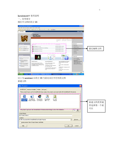
Installshield 9 使用说明一、向导部分刚打开文档时的主UI最近编辑文档以上为intallshiel后的主UI当前还未打开任何的文档新建文档新建文档类型通常选择第一个就可以向导UI1 2 3 4 5 6 7 8 9程序的基本信息,包括公司名称,程序名称,版本号以及公司网址等。
以上信息将会在安装过程中的UI中显示。
2.Installation architecture:组件的建立,类似于office安装过程中的程序模块选择。
例如。
在office安装过程中要全部安装,还是只安装word,excel等。
3.Application Files文件的添加:在此处将所有的程序要使用到的文件添加到这里。
主要包括以下文件夹3.1 script-defined folders:脚本定义文件夹:放到这里面的文件,其安装目录由脚本中FeatureSetTarget(MEDIA,"<para1>",para2);函数来重新定义。
para1在此定义的文件夹名。
Para2为目标文件夹名3.2 application target folder:安装目标文件夹。
即实际安装过程中的目标文件夹。
一般在安装过程中由用户来选择,当然可以指定默认。
3.3 program files:program file文件夹,如果有特定的文件必须放在此文件夹里。
就放这个位置吧。
3.4 windows:同上。
这两个文件夹是系统自动搜索的。
如果是自己安装的操作系统,比如将操作系统安装在其它盘符,一样可以搜到4.Application redistributables插件选择安装:如果你的程序需要以上的动态库连接,就打上5Application shortcuts快捷方式的建立点击New以后,会出现选择文件的对话框。
当然是已经在Application Files 中添加过的文件。
默认的可执行文件会自动添加。
如果不想用删掉即可6Application registery注册表添加:以上右击可以添加一个新的注册表项,其结构与windows自动的regedit十分类似。
PRO Series LCD Monitor PRO MP223 (3PB9) 用户指南说明书

PRO Series LCD Monitor PRO MP223 (3PB9)User GuideContentsGetting Started (3)Package Contents (3)Installing the Monitor Stand (4)Adjusting the Monitor (5)Monitor Overview (6)Connecting the Monitor to PC (8)OSD Setup (9)OSD Keys (9)OSD Menus (11)Professional (11)Image (13)Input Source (14)Navi Key (15)Setting (15)Specifications (17)Preset Display Modes (19)Troubleshooting (20)Safety Instructions (21)TÜV Rheinland Certification (23)Regulatory Notices (24)RevisionV1.0, 2023/032ContentsGetting StartedThis chapter provides you with the information on hardware setup procedures. While connecting devices, be careful in holding the devices and use a grounded wrist strap to avoid static electricity.∙Contact your place of purchase or local distributor if any of the items is damaged or missing.∙Package contents may vary by country.∙The included power cord is exclusively for this monitor and should not be used with other products.3Getting StartedInstalling the Monitor Stand1. Leave the monitor in its protective foam packaging. Align and gently push the stand bracket towards the monitor groove until it locks in place.2. Align and gently push the cable organizer towards the stand until it locks in place.3. Align and gently push the base towards the stand until it locks in place.4. Make sure the stand assembly is properly installed before setting the monitor Array∙Place the monitor on a soft, protected surface to avoid scratching the display panel.∙Do not use any sharp objects on the panel.∙This product comes with NO protective film to be removed by the user! Anymechanical damages to the product including removal of the polarizing film mayAdjusting the MonitorThis monitor is designed to maximize your viewing comfort with its adjustment capabilities.⚠ImportantAvoid touching the display panel when adjusting the monitor.5Getting StartedMonitor Overview6Getting Started7 Getting StartedConnecting the Monitor to PC1. Turn off your computer.2. Connect the video cable from the monitor to your computer.3. Assemble the external power supply & power cord. (Figure A)4. Connect the external power supply to the monitor power jack. (Figure B)5. Plug the power cord into the electrical outlet. (Figure C)6. Turn on the monitor. (Figure D)7. Power on the computer and the monitor will auto detect the signal source.8Getting StartedOSD Setup⚠ImportantThis chapter provides you with essential information on OSD Setup.All information is subject to change without prior notice.OSD KeysThe monitor comes with a set of OSD Keys that help to control the On-Screen Display (OSD) menu.9OSD Setup10OSD Setup11OSD MenusPress the M key to launch the On-Screen Display (OSD) main menu and use the OSD keys to tune the desired function to suit your personal preferences.12OSD Menus13 OSD Menus14OSD Menus15 OSD Menus16OSD Menus12V12V17Specifications18Specifications* Based on CIE1976 test standards.Preset Display ModesImportant19Preset Display ModesTroubleshootingThe power LED is off.• Press the monitor power button again.• Check if the monitor power cable is properly connected.No image.• Check if the computer graphics card is properly installed.• Check if the computer and monitor are connected to electrical outlets and areturned on.• Check if the monitor signal cable is properly connected.• The computer may be in Standby mode. Press any key to activate the monitor. The screen image is not properly sized or centered.• Refer to Preset Display Modes to set the computer to a setting suitable for themonitor to display.No Plug & Play.• Check if the monitor power cable is properly connected.• Check if the monitor signal cable is properly connected.• Check if the computer and graphics card are Plug & Play compatible. The icons, font or screen are fuzzy, blurry or have color problems.• Avoid using any video extension cables.• Adjust brightness and contrast.• Adjust RGB color or tune color temperature.• Check if the monitor signal cable is properly connected.• Check for bent pins on the signal cable connector.The monitor starts flickering or shows waves.• Change the refresh rate to match the capabilities of your monitor.• Update your graphics card drivers.• Keep the monitor away from electrical devices that may cause electromagneticinterference (EMI).20TroubleshootingSafety Instructions∙Read the safety instructions carefully and thoroughly.∙All cautions and warnings on the device or User Guide should be noted.∙Refer servicing to qualified personnel only.Power∙Make sure that the power voltage is within its safety range and has been adjusted properly to the value of 100~240V before connecting the device to the power outlet. ∙If the power cord comes with a 3-pin plug, do not disable the protective earth pin from the plug. The device must be connected to an earthed mains socket-outlet.∙Please confirm the power distribution system in the installation site shall provide the circuit breaker rated 120/240V, 20A (maximum).∙Always disconnect the power cord or switch the wall socket off if the device would be left unused for a certain time to achieve zero energy consumption.∙Place the power cord in a way that people are unlikely to step on it. Do not place anything on the power cord.∙If this device comes with an adapter, use only the MSI provided AC adapter approved for use with this device.BatteryPlease take special precautions if this device comes with a battery.∙Danger of explosion if battery is incorrectly replaced. Replace only with the same or equivalent type recommended by the manufacturer.∙Avoid disposal of a battery into fire or a hot oven, or mechanically crushing or cutting of a battery, which can result in an explosion.∙Avoid leaving a battery in an extremely high temperature or extremely low air pressure environment that can result in an explosion or the leakage of flammable liquid or gas.∙Do not ingest battery. If the coin/button cell battery is swallowed, it can cause severe internal burns and can lead to death. Keep new and used batteries away from children.European Union:Batteries, battery packs, and accumulators should not be disposed of asunsorted household waste. Please use the public collection system toreturn, recycle, or treat them in compliance with the local regulations. BSMI:廢電池請回收For better environmental protection, waste batteries should be collectedseparately for recycling or special disposal.21Safety InstructionsCalifornia, USA:The button cell battery may contain perchlorate material and requiresspecial handling when recycled or disposed of in California.For further information please visit: https:///perchlorate/ Environment∙To reduce the possibility of heat-related injuries or of overheating the device, do not place the device on a soft, unsteady surface or obstruct its air ventilators.∙Use this device only on a hard, flat and steady surface.∙To prevent the device from tipping over, secure the device to a desk, wall or fixedobject with an anti-tip fastener that helps to properly support the device and keep it safe in place.∙To prevent fire or shock hazard, keep this device away from humidity and hightemperature.∙Do not leave the device in an unconditioned environment with a storage temperature above 60℃ or below -20℃, which may damage the device.∙The maximum operating temperature is around 40℃.∙When cleaning the device, be sure to remove the power plug. Use a piece of softcloth rather than industrial chemical to clean the device. Never pour any liquid into the opening; that could damage the device or cause electric shock.∙Always keep strong magnetic or electrical objects away from the device.∙If any of the following situations arises, get the device checked by service personnel:• The power cord or plug is damaged.• Liquid has penetrated into the device.• The device has been exposed to moisture.• The device does not work well or you can not get it working according to the UserGuide.• The device has dropped and damaged.• The device has obvious sign of breakage.22Safety InstructionsTÜV Rheinland CertificationTÜV Rheinland Low Blue Light CertificationBlue light has been shown to cause eye fatigueand discomfort. MSI now offers monitors with TÜVRheinland Low Blue Light certification to ensureusers’ eye comfort and well-being. Please followthe instructions below to reduce the symptoms fromextended exposure to the screen and blue light.∙Place the screen 20 – 28 inches (50 – 70 cm) away from your eyes and a little below eye level.∙Consciously blinking the eyes every now and then will help to reduce eye strain after extended screen time.∙Take breaks for 20 minutes every 2 hours.∙Look away from the screen and gaze at a distant object for at least 20 seconds during breaks.∙Make stretches to relieve body fatigue or pain during breaks.∙Turn on the optional Low Blue Light function.TÜV Rheinland Flicker Free Certification∙TÜV Rheinland has tested this product toascertain whether the display produces visibleand invisible flicker for the human eye andtherefore strains the eyes of users.∙TÜV Rheinland has defined a catalogue oftests, which sets out minimum standardsat various frequency ranges. The test catalogue is based on internationally applicable standards or standards common within the industry and exceeds these requirements.∙The product has been tested in the laboratory according to these criteria.∙The keyword “Flicker Free” confirms that the device has no visible and invisible flicker defined in this standard within the range of 0 - 3000 Hz under various brightness settings.∙The display will not support Flicker Free when Anti Motion Blur/MPRT is enabled. (The availability of Anti Motion Blur/MPRT varies by products.)23TÜV Rheinland CertificationRegulatory NoticesCE ConformityThis device complies with the requirements set out in the Council Directive on the Approximation of the Laws of the Member States relating to Electromagnetic Compatibility (2014/30/EU), Low-voltage Directive (2014/35/EU), ErP Directive (2009/125/EC) and RoHS directive (2011/65/EU). This product has been tested and found to comply with the harmonized standards for Information Technology Equipment published under Directives of Official Journal of the European Union.FCC-B Radio Frequency Interference StatementThis equipment has been tested and found to comply with the limitsfor a Class B digital device, pursuant to Part 15 of the FCC Rules.These limits are designed to provide reasonable protection against harmful interference in a residential installation. This equipment generates, uses and can radiate radio frequency energy and, ifnot installed and used in accordance with the instruction manual, may cause harmful interference to radio communications. However, there is no guarantee that interference will not occur in a particular installation. If this equipment does cause harmful interference to radio or television reception, which can be determined by turning the equipment off and on, the user is encouraged to try to correct the interference by one or more of the measures listed below:∙Reorient or relocate the receiving antenna.∙Increase the separation between the equipment and receiver.∙Connect the equipment into an outlet on a circuit different from that to which thereceiver is connected.∙Consult the dealer or an experienced radio/television technician for help. Notice 1The changes or modifications not expressly approved by the party responsible for compliance could void the user’s authority to operate the equipment. Notice 2Shielded interface cables and AC power cord, if any, must be used in order to comply with the emission limits.This device complies with Part 15 of the FCC Rules. Operation is subject to the following two conditions:1. This device may not cause harmful interference, and2. This device must accept any interference received, including interference that maycause undesired operation.MSI Computer Corp.901 Canada Court, City of Industry, CA 91748, USA(626) 913-082824Regulatory NoticesWEEE StatementUnder the European Union (“EU”) Directive on Waste Electrical and Electronic Equipment, Directive 2012/19/EU, products of “electrical and electronic equipment” cannot be discarded as municipal waste anymoreand manufacturers of covered electronic equipment will be obligated totake back such products at the end of their useful life. Chemical Substances InformationIn compliance with chemical substances regulations, such as the EU REACH Regulation (Regulation EC No. 1907/2006 of the European Parliament and the Council), MSI provides the information of chemical substances in products at: https:///global/indexRoHS StatementJapan JIS C 0950 Material DeclarationA Japanese regulatory requirement, defined by specification JIS C 0950, mandates that manufacturers provide material declarations for certain categories of electronic products offered for sale after July 1, 2006.https:///global/Japan-JIS-C-0950-Material-DeclarationsIndia RoHSThis product complies with the “India E-waste (Management and Handling) Rule 2016” and prohibits use of lead, mercury, hexavalent chromium, polybrominated biphenylsor polybrominated diphenyl ethers in concentrations exceeding 0.1 weight % and 0.01 weight % for cadmium, except for the exemptions set in Schedule 2 of the Rule. Turkey EEE RegulationConforms to the EEE Regulations of the Republic Of TurkeyUkraine Restriction of Hazardous SubstancesThe equipment complies with requirements of the Technical Regulation, approved by the Resolution of Cabinet of Ministry of Ukraine as of 10 March 2017, № 139, in terms of restrictions for the use of certain dangerous substances in electrical and electronic equipment.Vietnam RoHSAs from December 1, 2012, all products manufactured by MSI comply with Circular 30/2011/TT-BCT temporarily regulating the permitted limits for a number of hazardous substances in electronic and electric products.25Regulatory Notices26Regulatory Notices Green Product Features∙Reduced energy consumption during use and stand-by ∙Limited use of substances harmful to the environment and health∙Easily dismantled and recycled ∙Reduced use of natural resources by encouraging recycling ∙Extended product lifetime through easy upgrades ∙Reduced solid waste production through take-back policy Environmental Policy ∙The product has been designed to enable proper reuse of parts and recycling and should not be thrown away at its end of life. ∙Users should contact the local authorized point of collection for recycling and disposing of their end-of-life products. ∙Visit the MSI website and locate a nearby distributor for further recycling information. ∙*******************************************************************disposal, take-back, recycling, and disassembly of MSI products.Warning!Overuse of screens is likely to affect eyesight.Recommendations: 1. Take a 10-minute break for every 30 minutes of screen time. 2. Children under 2 years of age should have no screen time. For children aged 2 years and over, screen time should be limited to less than one hour per day.Copyright and Trademarks Notice Copyright © Micro-Star Int’l Co., Ltd. All rights reserved. The MSI logo used is a registered trademark of Micro-Star Int’l Co., Ltd. All other marks and names mentioned may be trademarks of their respective owners. No warranty as to accuracy or completeness is expressed or implied. MSI reserves the right to make changes to this document without prior notice.Technical Support If a problem arises with your product and no solution can be obtained from the user’s manual, please contact your place of purchase or local distributor. Alternatively,please visit https:///support/ for further guidance.。
关于SetupFactory9的一些使用方法

关于SetupFactory9的⼀些使⽤⽅法
之前使⽤的VS⾃带的InstallShield2015LimitedEdition 打包⼯具,但是不太灵活,打包长得也难看;后来使⽤Setup Factory 9 打包winform 应⽤程序,⽤起来轻便灵活适合⽤于企业应⽤程序打包;下⾯分享⼀下使⽤⽅法
⼀:这⾥点击下载:,提取码:tt7a
⼆:下载完安装需要注册码,下载的⽂档⾥⾯已经放⼊注册码,复制粘贴就⾏
三:安装完后⼀定要注意下载的“dotnet4”⽂件夹,要把这个⽂件夹放在打包⼯具的根⽬录,否则打包会因缺少dotNetFx40_Full_x86_x64⽽出错,附下图
四:下⾯就是打包的过程了,废话少说直接附图吧
第⼀步:双击桌⾯的打包⼯具,会弹出提⽰框,直接点击ok
第⼆步:填写项⽬的基本信息
第三步:选择你的程序是32位还是64位,根据⾃⼰的需求选择
第四步:选择项⽬的根⽬录,直接点击下⼀步
第五步:直接下⼀步,直到出现下图界⾯,选择你喜欢的样式
第六步:选择语⾔模式此处为中⽂,如果你的其他语⾔能⼒⽐较强随意选择,继续下⼀步选择.NET 4,点击下⼀步
第七步:⼀直下⼀步直到出现下图,然后点击箭头所⽰,这样是筛选主要组件
第⼋步:此处可添加和删除安装过程中的程序执⾏步骤
第九步:点击箭头所⽰,设置安装包的输出位置,程序的名称和logo
第⼗步:在window设置快捷卸载
第⼗⼀步:双击程序的exe,第⼆图选择第⼀个可设置下次安装覆盖上⼀个版本,三图勾选⽣成桌⾯快捷⽅式
最后⼀步:点击箭头所⽰,然后⼀直下⼀步,到此打包完成
如果版本升级想要⾃动删除⽼版本参照此链接设置:。
Bind9安装设置指南

Bind9 安装设置指南目录[隐藏]•1 HOWTO Setup BIND9 DNS Server (如何安装设置 Bind9 DNS 服务器) o 1.1 Repositories 软件库o o1.2 Installing BIND9 (安装 BIND9) 1.3 BIND9 Scenarios 1.3.1 Caching Server(缓冲服务器) 1.3.2 Master Server(主服务器) 1.3.3 Slave Server(从服务器) 1.3.4 Hybrids(混和模式) 1.3.5 Stealth Servers(私密服务器) 1.4 DNS Record Types(DNS 记录类型) 1.4.1 Address Records(地址记录) 1.4.2 Alias Records(别名记录) 1.4.3 Mail Exchange Records(邮件交换记录) 1.4.4 Name Server Records(域名服务器记录)oo1.5 Configuring BIND9(配置 BIND9) 1.5.1 Caching Server(缓冲服务器) 1.5.2 Master Server(主服务器) 1.5.3 Slave Server(从服务器) 1.6 Chrooting BIND9 1.6.1 The Chroot Enviroment(Chroot 环境) 1.6.2 BIND9's Configuration(BIND9 的配置) 1.6.3 Ubuntu's syslogd Daemon Configuration (Ubuntu 的 syslogd 守护进程配置) 1.6.4 Restart the syslog server and BIND9(重启 syslog 服务及 BIND9) 1.7 Starting, Stopping, and Restarting BIND9(开始、停止 和重启 BIND9) 1.7.1 Status(状态) 1.8 Tips & Tricks(提示与技巧) 1.9 Additional Possibilities(附加功能) 1.10 Further Information(更多信息)ooo o o1.10.1 Online Recources(在线资源) 1.10.2 Printed Resources(印刷资源)[编辑 HOWTO 编辑] 编辑Setup BIND9 DNS Server (如何安装设置 Bind9 DNS服务器) 服务器)原文出处: 原文作者: 授权许可:• •创作共享协议 Attribution-ShareAlike 2.0 GNU 自由文档许可证翻译人员:FireHare 校正人员:purewind 贡献人员: 适用版本:This HOWTO is aimed to at people looking to learn how to configure and maintain a DNS server, such as for a network or to serve DNS zones for a domain name. 本指南是写给那些想学习如何配置和维护 DNS 服务器的人,例如为某个网络或者 DNS zones(DNS 域) 提供 Domain Name(域名)服务[编辑]Repositories软件库BIND9 is available in the core Ubuntu repository. No additional repository needs to be enabled for BIND9. BIND9 已经包含在 Ubuntu 核心库中,BIND9 并不需要启用其它附加库。
tp-link archer t9uh user 说明书

User GuideAC1900 High Gain Wireless Dual Band USB AdapterArcher T9UH© 2018 TP-Link REV2.0.0 1910011886ContentsAbout This Guide 1Chapter 1 Get to Know About Your Adapter2 1. 1. Product Overview . . . . . . . . . . . . . . . . . . . . . . . . . . . . . . . . . . . . . . . . . . . . . . . . . . . . . . . . . . 3 1. 2. LED Status . . . . . . . . . . . . . . . . . . . . . . . . . . . . . . . . . . . . . . . . . . . . . . . . . . . . . . . . . . . . . . . . . 3Chapter 2 Connect to a Computer 4Chapter 3 Windows 6 3. 1. Install Driver and WPS Tool. . . . . . . . . . . . . . . . . . . . . . . . . . . . . . . . . . . . . . . . . . . . . . . . . . 7 3. 2. Join a Wireless Network. . . . . . . . . . . . . . . . . . . . . . . . . . . . . . . . . . . . . . . . . . . . . . . . . . . . . 9 3. 3. Uninstall Driver and WPS Tool. . . . . . . . . . . . . . . . . . . . . . . . . . . . . . . . . . . . . . . . . . . . . . 10Chapter 4 Mac OS X 11 4. 1. Install Driver and Utility. . . . . . . . . . . . . . . . . . . . . . . . . . . . . . . . . . . . . . . . . . . . . . . . . . . . 12 4. 2. Join a Wireless Network. . . . . . . . . . . . . . . . . . . . . . . . . . . . . . . . . . . . . . . . . . . . . . . . . . . . 144. 2. 1. TP-Link Utility . . . . . . . . . . . . . . . . . . . . . . . . . . . . . . . . . . . . . . . . . . . . . . . . . . . . . 144. 2. 2. WPS (Wi-Fi Protected Setup). . . . . . . . . . . . . . . . . . . . . . . . . . . . . . . . . . . . . . . 15 4. 3. Management . . . . . . . . . . . . . . . . . . . . . . . . . . . . . . . . . . . . . . . . . . . . . . . . . . . . . . . . . . . . . 19 4. 4. Uninstall Driver and Utility. . . . . . . . . . . . . . . . . . . . . . . . . . . . . . . . . . . . . . . . . . . . . . . . . 20 Chapter 5 Linux 22Appendix: Troubleshooting 24About This GuideThis guide is a complement to Quick Installation Guide. The Quick Installation Guide instructs you on quick installation, and this guide provides the product overview and detailed instructions for each steps.When using this guide, please notice that features of the adapter may vary slightly depending on the model and software version you have. All screenshots, images, parameters and descriptions documented in this guide are used for demonstration only.ConventionsIn this guide, the following conventions are used:More Info• The latest software and utility can be found at Download Center at http://www.tp-link. com/support.• The Quick Installation Guide (QIG) can be found where you find this guide or inside the package of the product.• Specifications can be found on the product page at .• Our Technical Support contact information can be found at the Contact Technical Support page at /support.Chapter 1Get to Know About Your AdapterThis chapter introduces what the adapter can do and shows its appearance. This chapter contains the following sections:•Product Overview•LED StatusChapter 1Get to Know about Your Adapter1 1 Product OverviewTP-Link Wireless USB Adapter connects your computer to a Wi-Fi network for smooth HD video, voice streaming and online gaming.•Compatible with 802.11 ac/a/b/g/n products•Beamforming technology delivers a more targeted and highly efficient wireless connections•High gain antennas ensure superior range and stability•Equipped with a USB 3.0 cradle for flexible deployment•With WPS button, the adapter provides secured connection at the push of a button •Supports ad-hoc and infrastructure mode•Supports 64/128 bit WEP, WPA-PSK/WPA2-PSK•Supports Windows, Mac and Linux1 2 LED StatusYou can check the adapter’s working status by following the LED Explanation table.Tips:If the LED is off, try these troubleshooting tips:1. Check if the adapter is recognized and enabled or not. Refer to Troubleshooting-T2 for detailed instructions.2. Remove and reconnect the adapter.3. Reinstall the software, if necessary.Chapter 2Connect to a Computer This chapter introduces how to connect the adapter to your computer.Chapter 2Connect to a Computer Before you start using your adapter, insert the adapter into a USB port on your computer directly or connect the adapter to your computer using the USB cradle provided.Note:If interference appears on your computer’s monitor, try moving the adapter further from your computer.After connecting your adapter to the computer, please follow the instructions in the appropriate chapter for your operating system: Windows, Mac OS X, Linux.Chapter 3WindowsThis chapter introduces how to install your adapter’s driver and WPS Tool, use your adapter to join a wireless network, and uninstall your adapter in a Windows system. The adapter is equipped with a Setup Wizard, which can guide you through the installation process.This chapter includes the following sections:• Install Driver and WPS Tool• Join a Wireless Network• Uninstall Driver and WPS Tool3 1 Install Driver and WPS Tool1 Insert the resource CD into your CD drive and run the Autorun.exe from the pop-upAutoplay window.Note:1. You can also download the driver from the product’s Support page at www tp-link com.2. In some operating systems, the CD screen will pop up automatically. Otherwise, run the CD manually.2 Select Archer T9UH and follow the instructions to complete the installation.Note:If you can’t install the driver successfully, disable the antivirus software and firewall, then try again.3 When the following screen appears, the driver has been installed successfully.4 If you want to connect effortlessly with the push of a WPS button, click Yes andfollow the instructions to install the mini WPS Tool.Note:For Windows XP, WPS Tool is not supported. Please use Windows built-in wireless utility to join the wireless network.5 When the following screen appears, the WPS Tool has been installed successfully.You can enjoy connecting to your Wi-Fi with the push of the WPS button., (Network icon) on the taskbar. Select the Wi-Fi network you want to join, and click2. When the network icon changes to3. When the “Success!” message appears, your computer is connected to Wi-Fi.3 3 Uninstall Driver and WPS ToolThe software uninstallation steps vary a bit from different systems. Please follow the appropriate instructions for your Windows operating system: Windows 8/8.1/10, Windows XP/7.• Windows 8/8 1/10Go to Start menu to find the TP-Link application. Click Uninstall TP-Link Archer T9UH Driver, then follow the on-screen instructions to complete the uninstallation.• Windows XP/7Go to Start > All Programs > TP-Link > Uninstall TP-Link Archer T9UH Driver.Follow the on-screen instructions to complete the uninstallation.Chapter 4Mac OS XThis chapter introduces how to install your adapter’s driver and utility, use your adapter to join a wireless network, manage your adapter and uninstall your adapter in Mac OS X.This chapter includes the following sections:• Install Driver and Utility• Join a Wireless Network• Management• Uninstall Driver and Utility4 1 Install Driver and UtilityWe take the steps in Mac OS X 10.10 as an example - the steps may vary slightly for other versions of Mac OS.1 Download the driver and utility from this product’s Support page from TP-Link’sofficial website .Note:The CD is included in the package. If your computer has a CD drive, you can also run the included CD to install the driver and utility.2 Double click to unzip the downloaded folder and run the Install.pkg.3 The Install TP-Link Wireless USB Adapter Utility and Driver Wizard window willappear. Click Continue and follow the instructions to complete the installation.4 When the following screen appears, the driver and utility have been installedsuccessfully. Click Restart to finish the installation.5 After restarting the computer, the TP-Link Utility icon will appear on the menubar in the upper-right corner of the screen. To use the utility to join a Wi-Fi network with your adapter, refer to Join a Wireless Network.Note:If the TP-Link Utility icon does not appear on the menu bar, make sure the USB wireless network adapter is connected properly and its LED is on.4 2 Join a Wireless NetworkThere are two options of using the adapter to join a Wi-Fi network.Option 1: TP-Link UtilityTP-Link Utility lets you easily connect the adapter to a Wi-Fi network and manage the adapter.Option 2: WPS (Wi-Fi Protected Setup)WPS (Wi-Fi Protected Setup) is a network security standard for easily adding computers and other devices to a home network. Use this method if your wireless router or access point supports WPS.4 2 1 TP-Link UtilityOption 1Click the TP-Link Utility icon on the menu bar, and choose a Wi-Fi network from the list. Enter the password when prompted.When you are connected to the internet, the network icon will change to .Option 21 Click the TP-Link Utility icon on the menu bar, and then click Open WirelessUtility at the bottom of the network list.2 Select the network you want to join from the list and enter the password whenprompted. Click Join.Note:•2. The following screen indicates a successful connection by WPS. Click OK.Option 21. Press the WPS/QSS button on your router or AP.2. Within 2 minutes, click the TP-Link Utility icon on the menu bar, and then click WPS at the bottom of the network list.3. Click PBC.4. The following screen indicates a successful connection by WPS. Click OK.• PIN1. Click the TP-Link Utility icon on the menu bar, and then click WPS at the bottomof the network list.2. Click PIN.4. The following screen indicates a successful connection by WPS. Click OK.4 3 ManagementTP-Link Utility provides you with an easy way to manage various connection settings of your Wi-Fi network.1 Click the TP-Link Utility icon on the menu bar, and then click Open WirelessUtility at the bottom of the network list.2 TP-Link Utility will pop up. Click the Profiles button to open the Profiles screen.3 The Profiles screen lets you manage different Wi-Fi connection settings as profilesso that you can connect to your network easily.Preferred Networks displays the networks that you once connected to. The networks’ status and information are displayed on the table.• To join a Wi-Fi networkIf you want to join a Wi-Fi network that is listed on the profile screen, select the profile and click Apply in the bottom right corner.• To manage an existing profileIf you want to change the wireless settings of an existing profile, select it and then you can edit its Security and Password. If you want to delete a profile, select it and click Remove.4 4 Uninstall Driver and Utility1 Double click mand in the downloaded folder.2 Enter the password of you computer and when the “Uninstall Complete” messageappears, the uninstallation is complete.Chapter 5LinuxThis chapter introduces how to install your adapter’s driver in a Linux system.Chapter 5Linux Visit the TP-Link’s website at , and go to Archer T9UH’s product page. Then find the compatible version of driver in the support page. Download and install the driver on your computer.Appendix: Troubleshooting T1. W hat should I do if the adapter is not detected?• Make sure the adapter is securely connected to the computer.• Make sure you meet the minimum system requirements for the adapter and that the latest Windows and system updates are installed on your computer.• Make sure you use the latest driver for your specific adapter. The latest drivers can be found at the product’s Support page at .• If you are using the USB cradle that connects the USB adapter, try to connect the adapter directly to the computer.• Try a different USB port on the computer.• Try restarting the computer or try using the adapter on a different computer.T2. H ow to check if I have installed the driver for my adapter successfully or not?1. On your computer, please right click Computer icon and go to Manage;2. Open the Device Manager and go to Network adapters, and then find the corresponding TP-Link adapter, right click it and then go to Properties;3. If you can see “This device is working properly.” in the red box, you have already installed the driver successfully.T3. W hat should I do if can’t connect to the Wi-Fi after installing the driver?• Refer to T2to check if you have installed the driver for your adapter successfully .• Make sure the adapter is securely connected to the computer.• Disable the antivirus software and firewall, then try again.• Try a different USB port on the computer.• Re-install the driver and try again.T4. H ow to find the hardware version of the adapter?• The hardware version is printed on the product label on the package or the adapter. There is a character string “Ver:X.Y” (for example, Ver:2.0) in the Serial Number field, and the number X is the hardware version of the adapter.• Visit /faq-46.html and follow the second method to find the hardware version of the adapter.FCC STATEMENTThis equipment has been tested and found to comply with the limits for a Class B digital device, pursuant to part 15 of the FCC Rules. These limits are designed to provide reasonable protection against harmful interference in a residential installation. This equipment generates, uses and can radiate radio frequency energy and, if not installed and used in accordance with the instructions, may cause harmful interference to radio communications. However, there is no guarantee that interference will not occur in a particular installation. If this equipment does cause harmful interference to radio or television reception, which can be determined by turning the equipment off and on, the user is encouraged to try to correct the interference by one or more of the following measures:• Reorient or relocate the receiving antenna.• Increase the separation between the equipment and receiver.• Connect the equipment into an outlet on a circuit different from that to which the receiver is connected.• Consult the dealer or an experienced radio/ TV technician for help.This device complies with part 15 of the FCC Rules. Operation is subject to the following two conditions:1 ) This device may not cause harmful interference.2 ) This device must accept any interference received, including interference that maycause undesired operation.Any changes or modifications not expressly approved by the party responsible for compliance could void the user’s authority to operate the equipment.Note: The manufacturer is not responsible for any radio or TV interference caused by unauthorized modifications to this equipment. Such modifications could void the user’s authority to operate the equipment.FCC RF Radiation Exposure Statement:This equipment complies with FCC radiation exposure limits set forth for an uncontrolled environment. End users must follow the specific operating instructions for satisfying RF exposure compliance. This transmitter must not be co-located or operating in conjunction with any other antenna or transmitter. This equipment has been SAR-evaluated for use in hand. SAR measurements are based on a 5mm spacing from the body and that compliance is achieved at that distance.CE Mark WarningThis is a class B product. In a domestic environment, this product may cause radio interference, in which case the user may be required to take adequate measures. OPERATING FREQUENCY(the maximum transmitted power)2412MHz—2472MHz (20dBm)EU declaration of conformityTP-Link hereby declares that the device is in compliance with the essential requirements and other relevant provisions of directives 2014/53/EU and 2011/65/EU.The original EU declaration of conformity may be found at /en/ ce.RF Exposure InformationThis device meets the EU requirements (2014/53/EU Article 3.1a) on the limitation of exposure of the general public to electromagnetic fields by way of health protection. This device has been tested and meets the ICNIRP exposure guidelines and the European Standard EN 62209-2. SAR is measured with this device at a separation of 0.5 cm to the body, while transmitting at the highest certified output power level in all frequency bands of this device. Carry this device at least 0.5 cm away from your body to ensure exposure levels remain at or below the as-tested levels.Canadian Compliance StatementThis device complies with Industry Canada license-exempt RSSs. Operation is subject to the following two conditions:1 ) This device may not cause interference, and2 ) This device must accept any interference, including interference that may causeundesired operation of the device.Le présent appareil est conforme aux CNR d’Industrie Canada applicables aux appareils radio exempts de licence. L’exploitation est autorisée aux deux conditions suivantes :1 ) l’appareil ne doit pas produire de brouillage;2 ) l’utilisateur de l’appareil doit accepter tout brouillage radioélectrique subi, memesi le brouillage est susceptible d’en compromettre le fonctionnement. Radiation Exposure Statement:This EUT is compliance with SAR for general population/uncontrolled exposure limits in RSS-102 and had been tested in accordance with the measurement methods and procedures specified in IEEE 1528 and IEC 62209. This equipment should be installed and operated with minimum distance 1.0 cm between the radiator and your body. Thisdevice and its antenna(s) must not be co-located or operating in conjunction with any other antenna or transmitter.Déclaration d’exposition aux radiations:Cet équipement est conforme aux limites d’exposition aux rayonnements IC établies pour un environnement non contrôlé. Cet équipement doit être installé et utilisé avec un minimum de 20 cm de distance entre la source de rayonnement et votre corps. Industry Canada StatementCAN ICES-3 (B)/NMB-3(B)Korea Warning Statements당해 무선설비는 운용중 전파혼신 가능성이 있음.NCC Notice注意!依據 低功率電波輻射性電機管理辦法第十二條 經型式認證合格之低功率射頻電機,非經許可,公司、商號或使用者均不得擅自變更頻率、加大功率或變更原設計之特性或功能。
Computer Setup 工具设置说明书

Computer SetupNúmero de parte del documento: 383705-161 Mayo de 2005ContenidoComputer SetupAcceso a la utilidad Computer Setup . . . . . . . . . . . . . . 2Valores predeterminados de la utilidadComputer Setup. . . . . . . . . . . . . . . . . . . . . . . . . . . . . . . 3Menú Archivo . . . . . . . . . . . . . . . . . . . . . . . . . . . . . . . . 4Menú Seguridad. . . . . . . . . . . . . . . . . . . . . . . . . . . . . . . 5Menú Herramientas. . . . . . . . . . . . . . . . . . . . . . . . . . . . 6Menú Opciones avanzadas . . . . . . . . . . . . . . . . . . . . . . 6 IndiceComputer SetupLa utilidad Computer Setup es una utilidad preinstalada basadaen ROM que se puede usar incluso cuando el sistema operativono está funcionando o cuando no se puede cargar. Si el sistemaoperativo está funcionando, la computadora lo reinicia luego desalir de la utilidad Computer Setup.✎Los dispositivos señaladores no están admitidos en la utilidad Computer Setup. Debe utilizar el teclado para navegar yrealizar selecciones.✎Sólo se puede usar un teclado externo conectado mediante USB con la utilidad Computer Setup si el soporte heredado para USB está activado.Las tablas de menús, que aparecen posteriormente en estecapítulo, proporcionan información general acerca de lasopciones de la utilidad Computer Setup.Acceso a la utilidad Computer SetupSe puede obtener acceso a la información y a los parámetros deComputer Setup desde los menús Archivo, Seguridad,Herramientas y Opciones avanzadas.1.Abra la utilidad Computer Setup encendiendo o reiniciandola computadora y luego presione F10 mientras aparece elmensaje “F10 = ROM Based Setup” en el ángulo inferiorizquierdo de la pantalla.❏Para cambiar el idioma, presione F2.❏Para visualizar información acerca de la navegación,presione F1.❏Para volver al menú Computer Setup, presione la tecla Esc.2.Seleccione el menú Archivo, Seguridad, Herramientas uOpciones avanzadas.3.Para salir de la utilidad Computer Setup, utilice uno de lossiguientes métodos:❏Para salir de la utilidad Computer Setup sin guardar las preferencias, use las teclas de flecha para seleccionarArchivo > Omitir cambios y salir. Luego, siga lasinstrucciones que aparecen en pantalla.❏Para guardar las preferencias y salir de la utilidadComputer Setup, use las teclas de flecha para seleccionarArchivo > Guardar cambios y salir. Luego, siga lasinstrucciones que aparecen en pantalla.Las preferencias entran en vigencia cuando se reinicia lacomputadora.Valores predeterminados de la utilidad Computer SetupPara volver todos los parámetros de Computer Setup a los valoresconfigurados de fábrica:1.Abra la utilidad Computer Setup encendiendo o reiniciandola computadora y luego presione F10 mientras aparece elmensaje “F10 = ROM Based Setup” en el ángulo inferiorizquierdo de la pantalla.❏Para cambiar el idioma, presione F2.❏Para visualizar información acerca de la navegación,presione F1.e las teclas de flecha para seleccionar Archivo >Restaurar valores predeterminados y luego presione Intro.3.Seleccione la casilla de verificación Restaurar valorespredeterminados y luego presione Intro.4.Para confirmar la restauración, presione F10.5.Para guardar las preferencias y salir de la utilidad ComputerSetup, use las teclas de flecha para seleccionar Archivo >Guardar cambios y salir. Luego, siga las instrucciones queaparecen en pantalla.Las preferencias entran en vigencia cuando se reinicia lacomputadora.✎La configuración relacionada con la contraseña y la seguridad no se modifica n cuando restaura los valores predeterminadosde fábrica.Menú ArchivoSeleccione ParaInformación del sistema■Ver información de identificación acercade la computadora y de los paquetes debaterías del sistema.■Ver información de especificacionesacerca del procesador, del tamaño de lamemoria y del caché, de la revisión delvideo, de la versión del controlador delteclado y de la ROM del sistema. Guardar en disco flexible Guardar la configuración del sistema enun disquete.Restaurar desde disco flexible Restaurar la configuración del sistema desde un disquete.Restaurar valores predeterminados Reemplazar los parámetros de configuración por los valores predeterminados de fábrica en la utilidad Computer Setup. (La configuración relacionada con la contraseña y la seguridad no se modifica cuando restaura losparámetros predeterminados de fábrica).Omitir cambios y salir Cancelar los cambios ingresados durantela sesión actual. Luego, salir y reiniciarla computadora.Guardar cambios y salir Guardar los cambios ingresados durante lasesión actual. Luego, salir y reiniciar lacomputadora. Los cambios entran envigencia cuando se reinicia la computadora.Menú SeguridadSeleccione ParaContraseña de Administrador Ingresar, cambiar o eliminar una contraseñade administrador.Contraseña de encendido Ingresar, cambiar o eliminar una contraseñade encendido.Opciones de contraseña■Activar/desactivar la seguridad estricta.■Activar/desactivar la solicitud decontraseña al reiniciar la computadora. Contraseñas de DriveLock■Activar/desactivar DriveLock en el o losdiscos duros de la computadora.■Cambiar el usuario o la contraseñaprincipal de DriveLock.✎Sólo se puede acceder a laconfiguración de DriveLock cuandoingresa a la utilidad Computer Setupencendiendo la computadora(no reiniciándola).Seguridad de Smart Card Activar/desactivar el soporte para laautenticación de Smart Card durante el inicio.✎Este recurso sólo es admitido encomputadoras con Smart Card Reader(Lectores de Smart Card) opcionales. Seguridad de dispositivo■Activar/desactivar dispositivos del sistema.■Activar/desactivar el dispositivo de iniciode la unidad de CD-ROM, del disquetey de la tarjeta NIC.ID del sistema Ingresar la etiqueta de propiedad y titularidaddefinida por el usuario de la computadora.Menú HerramientasMenú Opciones avanzadas Seleccione Para Opciones de prueba automática de Disco Duro Ejecutar una prueba automática completa en cualquier disco duro del rmación de la bateríaVer información sobre el nivel de carga de la batería.Verificar la memoria.Ejecutar una verificación completa dela memoria del sistema.Seleccione Para Idioma (o presione F2)Cambiar el idioma de la utilidad Computer Setup.Opciones de inicio ■Establecer la demora de F10 y F12 durante el inicio.■Activar/desactivar MultiBoot, que establece un orden de inicio que puede incluir la mayoríade los dispositivos de inicio en el sistema.■Configurar el orden de inicio.(Continuación)Opciones de dispositivos ■Intercambiar las funciones de la tecla Fn y de la tecla Ctrl izquierda.■Activar/desactivar varios dispositivos señaladores estándar durante el inicio. (Para configurar lacomputadora de manera que admita sólo undispositivo señalador durante el inicio, por lo general no estándar, seleccione Desactivar.)■Activar/desactivar el soporte heredado para USB para teclado, mouse y concentrador USB.❐El teclado, el mouse y el concentrador USB funcionan aunque no haya un sistemaoperativo Windows cargado.❐La computadora se inicia desde un disco duro de inicio, un disquete de la unidad de disquete(sólo en algunos modelos) o un disco ópticoinsertado en una unidad conectada a lacomputadora (sólo en algunos modelos) o a undispositivo de acoplamiento opcional medianteun puerto USB.■Seleccionar un modo de puerto paralelo: EPP (Puerto paralelo mejorado), estándar,bidireccional o ECP (Puerto concapacidades mejoradas).■Automático/desactivar la TecnologíaIntel SpeedStep.■Activar/desactivar el ventilador del sistema cuando está conectado a un enchufe de CA.■Activar/desactivar PSAE Execution Disable de Intel o AMD (sólo en algunos modelos).■Activar/desactivar la radio del dispositivo WLAN (sólo en algunos modelos).■Activar/desactivar la radio del dispositivo Bluetooth incorporada (sólo en algunos modelos).■Activar/desactivar la alternancia entre LAN y WLAN (sólo en algunos modelos).■Activar/desactivar el ahorro de energía de la LAN (sólo en algunos modelos).Seleccione ParaIndiceAahorro de energía de la LAN7 alternancia entre LAN y WLAN7CComputer Setupacceso2menú Archivo4menú Herramientas6menú Opcionesavanzadas6menú Seguridad5restauración de valorespredeterminados3 contraseñas5 controladores, ordende inicio6Ddispositivos señaladores7EExecution Disable7Iidioma, cambio en Computer Setup6información de la batería6 información del sistema4Intel SpeedStep7Mmenú Archivo4menú Herramientas6menú Opciones avanzadas6 menú Seguridad5modo de puerto paralelo7Nnúmero de serie, computadora4Oopciones de inicio6orden de inicio6Pprueba de disco duro6Rradio del dispositivo Bluetooth7radio del dispositivo WLAN7 restaurar valores predeterminados3Ssoporte heredado para USB7TTecnología SpeedStep7UUtilidad de Configuraciónacceso2menú Archivo4menú Herramientas6menú Opcionesavanzadas6menú Seguridad5restauración deconfiguraciónpredeterminada3Vventilador del sistema7verificación de memoria6Indice–2Computer Setup© Copyright 2005 Hewlett-Packard Development Company, L.P. Microsoft y Windows son marcas comerciales registradas de Microsoft Corporation en EE.UU. Bluetooth es una marca comercial que pertenece a su titular y que Hewlett-Packard Company utiliza con la debida licencia. Intel es una marca comercial o marca comercial registrada de Intel Corporation o de sus subsidiarias en EE.UU. y en otros países.La información de este documento está sujeta a cambios sin previo aviso. Las únicas garantías para los productos y servicios de HP están establecidas en las declaraciones de garantía limitada que acompañan a esos productos y servicios. Nada de lo contenido en este documento debe interpretarse como parte de una garantía adicional. HP no será responsable de omisiones ni errores técnicos o editoriales contenidos en este documento.Computer SetupPrimera edición: Mayo de 2005Número de parte del documento: 383705-161。
- 1、下载文档前请自行甄别文档内容的完整性,平台不提供额外的编辑、内容补充、找答案等附加服务。
- 2、"仅部分预览"的文档,不可在线预览部分如存在完整性等问题,可反馈申请退款(可完整预览的文档不适用该条件!)。
- 3、如文档侵犯您的权益,请联系客服反馈,我们会尽快为您处理(人工客服工作时间:9:00-18:30)。
U SING M AYA :C HARACTER S ETUP109使用正弦非线性变形正弦变形沿正弦曲线改变物体的形状。
本节包括下列内容:z 了解正弦变形(109页) z 创建正弦变形(110页) z 编辑正弦变形效果(112页) z删除正弦变形(115页)了解正弦变形正弦变形能使用户沿正弦曲线起伏可变形物体。
它们可应用于角色创建和建模。
正弦变形包含手柄,使用它可直观地控制正弦作用的范围、振幅和波长。
9U SING M AYA C HARACTER S ETUP相关MEL命令与正弦变形有关的MEL命令有:z NonLinearz ReorderDeformers关于这些命令详见在线文件MEL Command Reference。
从属图节点正弦变形的从属图节点包括:z正弦变形运算节点(默认名:sine n,也要注意deformSine 和 nonLinear节点)z正弦变形手柄节点(默认名:sine n Handle)z正弦变形手柄形状节点(默认名:sine n HandleShape)z正弦变形设置节点(默认名:sine n Set)z扭曲点(默认名:tweak n)关于这些节点,详见在线文件DG Node Reference部分。
创建正弦变形当创建正弦变形时,可先设置创建选项后创建变形,或使用当前创建选项直接创建变形。
如果不清楚当前的创建选项设置,可先进行检查,这可节省以后调节变形属性的时间。
在创建变形后避免改变物体点的数目在创建变形后,用户应该避免改变可变形物体点的数目(例如,CVs、顶点或晶格点)。
如果改变了点的数目,可导致意想不到的变形结果。
在开始使用变形时,用户应尽量满足变形物体的拓扑结构,也可以保存一个副本,以便于进一步的建模。
设置创建选项设置创建选项:U SING M AYA:C HARACTER S ETUP P ART 2 110U SING S INE N ONLINEAR D EFORMERS91 如果现在想创建变形,选择要变形的物体。
2 选择Deform > Create Nonlinear > Sine-命令。
那么Create Sine Deformer Options视窗显示。
3 单击Basic 和 Advanced标签设置创建选项。
BasicLow Bound(下限)设置变形沿物体的局部Y轴负向作用的范围。
值可以是负数或0,使用滑块可设置从-10.0000到0.0000的值。
默认值为-1.0000。
High Bound(上限)设置变形沿物体的局部Y轴正向作用的范围。
值为正数(包括最小值0),使用滑块可设置0.0000到10.0000的值。
默认值为1.0000。
Amplitude(振幅)设置正弦曲线的振幅(波的最大数量)。
使用滑块可设置-5.0000到5.0000间的值。
默认值为0.0000(没有波动)。
Wavelength(波长)设置沿变形的局部Y轴的正弦曲线频率。
频率值增大,将减少波长;频率减小,波长增大。
使用滑块可设置从-0.1000到10.0000间的值。
默认值为2.0000。
Dropoff(衰减)设置振幅的衰减方式。
负值设置向变形手柄的中心衰减,正值设置从变形手柄中心向外衰减。
使用滑块可设置从-1.0000到1.0000间的值。
默认值为0.0000(没有衰减)。
Offset(偏移)设置正弦曲线与变形手柄中心的位置关系。
改变该值可创建扭动效果。
使用滑块可设置从-10.0000到10.0000间的值。
默认设置为0.0000。
Advanced请看“编辑高级变形创建选项”(29页)。
z单击Create按钮,创建正弦变形。
或z单击Save,保存创建选项,但不创建正弦变形。
D EFORMERS U SING M AYA:C HARACTER S ETUP111U SING M AYA C HARACTER S ETUP或z单击Reset回到默认创建选项。
或z单击Close关闭视窗。
创建正弦变形创建正弦变形:1 选择要变形的物体。
2 选择Deform > Create Nonlinear > Sine命令。
Maya使用当前创建选项创建正弦变形。
正弦变形手柄作为当前选择物体显示在场景中。
正弦变形手柄(及其枢轴点)被放置在物体的中心。
在Outliner中,正弦变形手柄被列出(默认名是:sine n Handle)。
在通道盒,sine n Handle 和sine n HandleShape节点被选择。
编辑正弦变形效果在创建正弦变形后,它的手柄显示在场景中,它的节点在通道盒列出。
节点包括正弦手柄节点(默认名:sine n Handle)、正弦手柄形状节点(sine n HandleShape)和正弦变形节点(默认名:sine n)。
可通过编辑正弦手柄节点和正弦变形节点编辑正弦变形效果。
可移动、旋转和缩放正弦手柄来编辑变形效果。
也可以编辑正弦变形节点的可设置关键帧属性(通道),它们显示在通道盒中。
可使用下列方式编辑正弦变形效果:z操纵正弦变形手柄z编辑正弦变形通道z编辑正弦变形属性U SING M AYA:C HARACTER S ETUP P ART 2 112U SING S INE N ONLINEAR D EFORMERS9操纵正弦变形手柄使用手柄操纵器编辑正弦变形效果:1 选择正弦变形节点(默认名:sinen)。
2 选择Show Manipulator Tool(快捷键:T键)。
3 注意正弦变形手柄的操纵器。
这些能使用户直观地编辑属性。
4 在场景中,选择其中的一个正弦变形操纵器。
按住鼠标中键,移动鼠标进行交互式地编辑。
注意在通道盒中会即时改变用户所改变的参数值。
通过移动、旋转或缩放手柄编辑:1 选择正弦变形手柄节点(默认名:sine n Handle)。
2 移动、旋转或缩放手柄改变变形效果。
3 按下键盘上的Insert键,移动或缩放手柄,然后再次按下Insert键。
记住用户可以访问变形手柄的局部坐标轴(Display > Object Components > Local RotationAxes),旋转和缩放枢轴(Display > Object Components > Rotate Pivots 或者Scale Pivots)和选择手柄(Display > Object Components > Selection Handle)。
编辑正弦变形通道D EFORMERS U SING M AYA:C HARACTER S ETUP113U SING M AYA C HARACTER S ETUP通道是显示在通道盒中,可设置关键帧的属性。
通道盒提供了编辑正弦变形手柄的便利方式。
使用属性编辑器可编辑所有的属性。
(参看“编辑正弦变形属性”(114页))。
使用通道盒编辑:1 选择正弦变形节点(默认名:sine n)。
选择变形物体,然后在通道盒的变形历史中(在INPUTS下)选择变形节点,这是一种选择变形节点的快速方式。
注意使用Channel Control编辑器(选择Window)> General Editors > Channel Control)可以控制哪些作为可设置关键帧属性的属性显示在通道盒中。
2 在通道盒中,在系统默认设置下,列出了下列属性。
Envelope设置变形缩放系数。
默认值为1。
Amplitude(振幅)设置正弦曲线的振幅(最大波动数量)。
默认值为0(没有波动)。
Wavelength(波长)设置沿变形的局部Y轴的正弦曲线频率。
频率值增大,将减少波长;频率减小,波长增大。
使用滑块可设置从-0.1000到10.0000间的值。
默认值为2。
Offset(偏移)设置正弦曲线与变形手柄中心的位置关系。
改变该值可创建扭动效果。
系统默认设置为0。
Dropoff(衰减)设置振幅的衰减方式。
负值设置向变形手柄的中心衰减(最大值是-1),正值设置从变形手柄中心向外衰减(最大值是1)。
默认值为0(没有衰减)。
Low Bound(下限)设置变形沿物体的局部Y轴负向作用的范围。
值可以是负数或0。
默认值为-1。
High Bound(上限)设置变形沿物体的局部Y轴正向作用的范围。
值可为正数(包括最小值0)。
默认值为1。
3 使用鼠标左键单击通道名。
4 在场景中,按下鼠标中键并左右移动。
通过移动鼠标,可直观地改被变选择通道的值。
当U SING M AYA:C HARACTER S ETUP P ART 2 114U SING S INE N ONLINEAR D EFORMERS 9D EFORMERS U SING M AYA :C HARACTER S ETUP115移动鼠标时,按住Ctrl 键,可进行精确地控制;按住Shift 键,可进行粗略地控制。
编辑正弦变形属性:使用属性编辑器编辑:1 选择正弦变形节点(默认名:sine n )。
2 选择Windows > Attribute Editor 或按下快捷键(Ctrl+A ),打开属性编辑器。
3 在属性编辑器中列出了下列属性:Nonlinear Deformer Attributes 、 Deformer Attributes 、 Node Behavior 和 Extra Attributes 。
Nonlinear Deformer Attributes (非线性变形属性)Amplitude (振幅) 设置正弦曲线的振幅。
使用滑块可设置-5.0000到5.0000间的值。
默认值为0.0000(没有波动)。
Wavelength (波长)设置沿变形的局部Y 轴的正弦曲线频率。
频率值增大,将减少波长;频率减小,波长增大。
使用滑块可设置从0.100到10.0000间的值。
默认值为2.000。
Offset (偏移)设置正弦曲线与变形手柄中心的位置关系。
改变该值可创建扭动效果。
使用滑块可设置从-10.0000到10.0000间的值。
默认设置为0.000。
Dropoff (衰减) 设置振幅的衰减方式。
负值设置向变形手柄的中心衰减,正值设置从变形手柄中心向外衰减。
使用滑块可设置从-1.0000到1.0000间的值。
默认值为0.000(没有衰减)。
Low Bound (下限)设置变形沿物体的局部Y 轴负向作用的范围。
值可以是负数或0,使用滑块可设置从-10.000到0.000的值。
默认值为-1.000。
High Bound (上限)设置变形沿物体的局部Y 轴正向作用的范围。
值为正数(包括最小值0.000)。
使用滑块可设置0.000到10.000的值。
默认值为1.000。
Deformer Attributes (变形属性)Envelope设置变形手柄缩放系数。