MAX6333UR24D3中文资料
FDC6333C资料

Features
• Q1 2.5 A, 30V. RDS(ON) = 95 mΩ @ VGS = 10 V RDS(ON) = 150 mΩ @ VGS = 4.5 V • Q2 –2.0 A, 30V. RDS(ON) = 150 mΩ @ VGS = –10 V RDS(ON) = 220 mΩ @ VGS = –4.5 V • Low gate charge • High performance trench technology for extremely low RDS(ON). • SuperSOT –6 package: small footprint (72% smaller than SO-8); low profile (1mm thick).
(Note 2)
TA = 25°C unless otherwise noted
Test Conditions
VGS = 0 V, ID = 250 µA VGS = 0 V, ID = –250 µA ID = 250 µA,Ref. to 25°C ID = –250 µA,Ref. to 25°C VDS = 24 V, VGS = 0 V VDS = –24 V, VGS = 0 V VGS = 16 V, VDS = 0 V VGS = 25 V, VDS = 0 V VGS = –16 V, VDS = 0 V VGS = –25 V, VDS = 0 V VDS = VGS, ID = 250 µA VDS = VGS, ID = –250 µA ID = 250 µA,Ref. To 25°C ID = –250 µA,Ref. to 25°C VGS = 10 V, ID = 2.5 A VGS = 4.5 V, ID = 2.0 A VGS = 10 V, ID = 2.5 A,TJ=125°C VGS = –10 V, ID = –2.0 A VGS =– 4.5 V, ID = –1.7 A VGS = 10 V, ID= –2.0 A,TJ=125°C VGS = 10 V, VDS = 5 V VDS = –5 V VDS = 5 V ID = 2.5 A ID = –2.0A Q1 Q2 Q1 Q2 Q1 Q2 Q1 Q2 Q1 Q2
MAX830中文资料

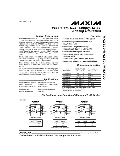
STEP-DOWN CONVERTER
* CoilCraft DO3316-104
________________________________________________________________ Maxim Integrated Products
1
Call toll free 1-800-998-8800 for free samples or literature.
* THIS THERMAL RESISTANCE NUMBER IS WITH THE DEVICE WELL MOUNTED ON 1 oz. COPPER WITH THERMAL PASTE BETWEEN THE IC AND THE UNDERLYING GROUND PLANE. LOWER THERMAL RESISTANCE IS POSSIBLE (SEE APPLICATIONS SECTION).
NUAL KIT MA ATION U EET L H A S V A E T WS DA FOLLO
___________________________Features
o Input Range: Up to 30V o 1A On-Chip Power Switch o Adjustable Output (MAX830) Fixed Outputs: 5V (MAX831) 3.3V (MAX832) 3V (MAX833) o 100kHz Switching Frequency o Excellent Dynamic Characteristics o Few External Components o 8mA Quiescent Current o 16-Pin SO Package o Evaluation Kit Available
MAX3232中文资料zhuanzai

MAX3222/MAX3232/MAX3237/MAX32413.0V至5.5V、低功耗、1Mbps、真RS-232收发器,使用四只0.1µF外部电容________________________________________________________________Maxim Integrated Products119-0273; Rev 7; 1/07MegaBaud和UCSP是Maxim Integrated Products, Inc.的商标。
本页已使用福昕阅读器进行编辑。
M A X 3222/M A X 3232/M A X 3237/M A X 32413.0V至5.5V、低功耗、1Mbps、真RS-232收发器,使用四只0.1µF外部电容2_______________________________________________________________________________________ABSOLUTE MAXIMUM RATINGSELECTRICAL CHARACTERISTICS(V CC = +3.0V to +5.5V, C1–C4 = 0.1µF (Note 2), T A = T MIN to T MAX , unless otherwise noted. Typical values are at T A = +25°C.)Stresses beyond those listed under “Absolute Maximum Ratings” may cause permanent damage to the device. These are stress ratings only, and functional operation of the device at these or any other conditions beyond those indicated in the operational sections of the specifications is not implied. Exposure to absolute maximum rating conditions for extended periods may affect device reliability.Note 1:V+ and V- can have a maximum magnitude of 7V, but their absolute difference cannot exceed 13V.V CC ...........................................................................-0.3V to +6V V+ (Note 1)...............................................................-0.3V to +7V V- (Note 1)................................................................+0.3V to -7V V+ + V- (Note 1)...................................................................+13V Input VoltagesT_IN, SHDN , EN ...................................................-0.3V to +6V MBAUD...................................................-0.3V to (V CC + 0.3V)R_IN.................................................................................±25V Output VoltagesT_OUT...........................................................................±13.2V R_OUT....................................................-0.3V to (V CC + 0.3V)Short-Circuit DurationT_OUT....................................................................ContinuousContinuous Power Dissipation (T A = +70°C)16-Pin TSSOP (derate 6.7mW/°C above +70°C).............533mW 16-Pin Narrow SO (derate 8.70mW/°C above +70°C)....696mW 16-Pin Wide SO (derate 9.52mW/°C above +70°C)........762mW 16-Pin Plastic DIP (derate 10.53mW/°C above +70°C)...842mW 18-Pin SO (derate 9.52mW/°C above +70°C)..............762mW 18-Pin Plastic DIP (derate 11.11mW/°C above +70°C)..889mW 20-Pin SSOP (derate 7.00mW/°C above +70°C).........559mW 20-Pin TSSOP (derate 8.0mW/°C above +70°C).............640mW 28-Pin TSSOP (derate 8.7mW/°C above +70°C).............696mW 28-Pin SSOP (derate 9.52mW/°C above +70°C).........762mW 28-Pin SO (derate 12.50mW/°C above +70°C).....................1W Operating Temperature RangesMAX32_ _C_ _.....................................................0°C to +70°C MAX32_ _E_ _ .................................................-40°C to +85°C Storage Temperature Range.............................-65°C to +150°C Lead Temperature (soldering, 10s).................................+300°CMAX3222/MAX3232/MAX3237/MAX32413.0V至5.5V、低功耗、1Mbps、真RS-232收发器,使用四只0.1µF外部电容_______________________________________________________________________________________3TIMING CHARACTERISTICS—MAX3222/MAX3232/MAX3241(V CC = +3.0V to +5.5V, C1–C4 = 0.1µF (Note 2), T A = T MIN to T MAX , unless otherwise noted. Typical values are at T A = +25°C.)ELECTRICAL CHARACTERISTICS (continued)(V CC = +3.0V to +5.5V, C1–C4 = 0.1µF (Note 2), T A = T MIN to T MAX , unless otherwise noted. Typical values are at T A = +25°C.)M A X 3222/M A X 3232/M A X 3237/M A X 32413.0V至5.5V、低功耗、1Mbps、真RS-232收发器,使用四只0.1µF外部电容4________________________________________________________________________________________________________________________________________________________________典型工作特性(V CC = +3.3V, 235kbps data rate, 0.1µF capacitors, all transmitters loaded with 3k Ω, T A = +25°C, unless otherwise noted.)-6-5-4-3-2-101234560MAX3222/MAX3232TRANSMITTER OUTPUT VOLTAGEvs. LOAD CAPACITANCELOAD CAPACITANCE (pF)T R A N S M I T T E R O U T P U T V O L T A G E (V )20003000100040005000246810121416182022150MAX3222/MAX3232SLEW RATEvs. LOAD CAPACITANCELOAD CAPACITANCE (pF)S L E W R A T E (V /µs )20003000100040005000510152025303540MAX3222/MAX3232SUPPLY CURRENT vs. LOAD CAPACITANCEWHEN TRANSMITTING DATALOAD CAPACITANCE (pF)S U P P L Y C U R R E N T (m A )20003000100040005000TIMING CHARACTERISTICS—MAX3237(V CC = +3.0V to +5.5V, C1–C4 = 0.1µF (Note 2), T A = T MIN to T MAX , unless otherwise noted. Typical values are at T A = +25°C.)Note 2:MAX3222/MAX3232/MAX3241: C1–C4 = 0.1µF tested at 3.3V ±10%; C1 = 0.047µF, C2–C4 = 0.33µF tested at 5.0V ±10%.MAX3237: C1–C4 = 0.1µF tested at 3.3V ±5%; C1–C4 = 0.22µF tested at 3.3V ±10%; C1 = 0.047µF, C2–C4 = 0.33µF tested at 5.0V ±10%.Note 3:Transmitter input hysteresis is typically 250mV.MAX3222/MAX3232/MAX3237/MAX32413.0V至5.5V、低功耗、1Mbps、真RS-232收发器,使用四只0.1µF外部电容_______________________________________________________________________________________5-7.5-5.0-2.502.55.07.50MAX3241TRANSMITTER OUTPUT VOLTAGEvs. LOAD CAPACITANCELOAD CAPACITANCE (pF)T R A N S M I T T E R O U T P U T V O L T A G E (V )2000300010004000500046810121416182022240MAX3241SLEW RATEvs. LOAD CAPACITANCELOAD CAPACITANCE (pF)S L E W R A T E (V /µs )20003000100040005000510152025303545400MAX3241SUPPLY CURRENT vs. LOADCAPACITANCE WHEN TRANSMITTING DATALOAD CAPACITANCE (pF)S U P P L Y C U R R E N T (m A )20003000100040005000-7.5-5.0-2.502.55.07.50MAX3237TRANSMITTER OUTPUT VOLTAGE vs. LOAD CAPACITANCE (MBAUD = GND)LOAD CAPACITANCE (pF)T R A N S M I T T E R O U T P U T V O L T A G E (V )200030001000400050000102030504060700MAX3237SLEW RATE vs. LOAD CAPACITANCE(MBAUD = V CC )LOAD CAPACITANCE (pF)S L E W R A T E (V /µs )500100015002000-7.5-5.0-2.502.55.07.50MAX3237TRANSMITTER OUTPUT VOLTAGE vs. LOAD CAPACITANCE (MBAUD = V CC )LOAD CAPACITANCE (pF)T R A N S M I T T E R O U T P U T V O L T A G E (V )5001000150020001020304050600MAX3237SUPPLY CURRENT vs.LOAD CAPACITANCE (MBAUD = GND)LOAD CAPACITANCE (pF)S U P P L Y C U R R E N T (m A )200030001000400050000246810120MAX3237SLEW RATE vs. LOAD CAPACITANCE(MBAUD = GND)LOAD CAPACITANCE (pF)S L E W R A T E (V /µs )2000300010004000500010302040506070MAX3237SKEW vs. LOAD CAPACITANCE(t PLH - t PHL )LOAD CAPACITANCE (pF)1000150050020002500____________________________________________________________________典型工作特性(续)(V CC = +3.3V, 235kbps data rate, 0.1µF capacitors, all transmitters loaded with 3k Ω, T A = +25°C, unless otherwise noted.)M A X 3222/M A X 3232/M A X 3237/M A X 32413.0V至5.5V、低功耗、1Mbps、真RS-232收发器,使用四只0.1µF外部电容6_________________________________________________________________________________________________________________________________________________________________引脚说明MAX3222/MAX3232/MAX3237/MAX32413.0V至5.5V、低功耗、1Mbps、真RS-232收发器,使用四只0.1µF外部电容_______________________________________________________________________________________7_______________________________详细说明双电荷泵电压转换器MAX3222/MAX3232/MAX3237/MAX3241的内部电源由两路稳压型电荷泵组成,只要输入电压(V CC )在3.0V至5.5V范围以内,即可提供+5.5V (倍压电荷泵)和-5.5V (反相电荷泵)输出电压。
MAX320-MAX322中文资料
ELECTRICAL CHARACTERISTICS
(V+ = +5V ±10%, V- = -5V ±10%, VINH = 3.5V, VINL = 2.5V, TA = TMIN to TMAX, unless otherwise noted.)
PARAMETER ANALOG SWITCH Analog Signal Range
For equivalent devices specified for single-supply operation, see the MAX323/MAX324/MAX325 data sheet. For quad versions of these switches, see the MAX391/MAX392/MAX393 data sheet.
Plastic DIP (derate 9.09mW/°C above +70°C) .............727mW Narrow SO (derate 5.88mW/°C above +70°C) .............471mW
µMAX (derate 4.10mW/°C above +70°C) .....................330mW CERDIP (derate 8.00mW/°C above +70°C) ..................640mW Operating Temperature Ranges MAX32_C_ _ ........................................................0°C to +70°C MAX32_E_ _......................................................-40°C to +85°C MAX32_MJA ...................................................-55°C to +125°C Storage Temperature Range .............................-65°C to +150°C Lead Temperature (soldering, 10sec) .............................+300°C
ISL6334DIRZ中文资料

GND
30 ISEN329 ISEN3+ 28 ISEN1+ 27 ISEN126 PWM1 25 PWM4 24 ISEN423 ISEN4+ 22 ISEN2+ 21 ISEN2-
• Average Overcurrent Protection and Channel Current Limit
• Precision Overcurrent Protection on IMON Pin
• Thermal Monitoring and Overvoltage Protection
• Integrated Programmable Temperature Compensation
• Integrated Open Sense Line Protection
• 1- to 4-Phase Operation, Coupled Inductor Compatibility
• Adjustable Switching Frequency up to 1MHz Per Phase
Pinout
ISL6334D (40 LD QFN) TOP VIEW
VID7 TM VR_HOT VR_FAN VR_RDY SS FS EN_VTT EN_PWR PWM3
40 39 38 37 36 35 34 33 32 31
VID6 1 VID5 2 VID4 3 VID3 4 VID2 5 VID1 6 VID0 7 PSI# 8 OFS 9 IMON 10
• Package Option - QFN Compliant to JEDEC PUB95 MO-220 QFN - Quad Flat No Leads - Product Outline
MAX323_datasheet
________________General DescriptionThe MAX3222/MAX3232/MAX3237/MAX3241 trans-ceivers have a proprietary low-dropout transmitter out-put stage enabling true RS-232 performance from a 3.0V to 5.5V supply with a dual charge pump. The devices require only four small 0.1µF external charge-pump capacitors. The MAX3222, MAX3232, and MAX3241 are guaranteed to run at data rates of 120kbps while maintaining RS-232 output levels. The MAX3237 is guaranteed to run at data rates of 250kbps in the normal operating mode and 1Mbps in the MegaBaud™ operating mode, while maintaining RS-232output levels.The MAX3222/MAX3232 have 2 receivers and 2 drivers. The MAX3222 features a 1µA shutdown mode that reduces power consumption and extends battery life in portable systems. Its receivers remain active in shutdown mode, allowing external devices such as modems to be monitored using only 1µA supply cur-rent. The MAX3222 and MAX3232 are pin, package,and functionally compatible with the industry-standard MAX242 and MAX232, respectively.The MAX3241 is a complete serial port (3 drivers/5 receivers) designed for notebook and subnotebook computers. The MAX3237 (5 drivers/3 receivers) is ideal for fast modem applications. Both these devices feature a shutdown mode in which all receivers can remain active while using only 1µA supply current. Receivers R1(MAX3237/MAX3241) and R2 (MAX3241) have extra out-puts in addition to their standard outputs. These extra outputs are always active, allowing external devices such as a modem to be monitored without forward bias-ing the protection diodes in circuitry that may have V CC completely removed.The MAX3222, MAX3237, and MAX3241 are available in space-saving TSSOP and SSOP packages.________________________ApplicationsNotebook, Subnotebook, and Palmtop Computers High-Speed ModemsHand-Held Equipment Peripherals Printers3.0V to 5.5V , Low-Power , up to 1Mbps, T rue RS-232Transceivers Using Four 0.1µF External CapacitorsMegaBaud and UCSP are trademarks of Maxim Integrated Products, Inc.Typical Operating Circuits appear at end of data sheet.MAX3222/MAX3232/ MAX3237/MAX3241捷多邦,您值得信赖的PCB打样专家!3.0V to 5.5V , Low-Power , up to 1Mbps, T rue RS-232Transceivers Using Four 0.1µF External CapacitorsABSOLUTE MAXIMUM RATINGSELECTRICAL CHARACTERISTICS(V CC = +3.0V to +5.5V, C1–C4 = 0.1µF (Note 2), T A = T MIN to T MAX , unless otherwise noted. Typical values are at T A = +25°C.)Stresses beyond those listed under “Absolute Maximum Ratings” may cause permanent damage to the device. These are stress ratings only, and functional operation of the device at these or any other conditions beyond those indicated in the operational sections of the specifications is not implied. Exposure to absolute maximum rating conditions for extended periods may affect device reliability.Note 1:V+ and V- can have a maximum magnitude of 7V, but their absolute difference cannot exceed 13V.V CC ...........................................................................-0.3V to +6V V+ (Note 1)...............................................................-0.3V to +7V V- (Note 1)................................................................+0.3V to -7V V+ + V- (Note 1)...................................................................+13V Input VoltagesT_IN, SHDN , EN ...................................................-0.3V to +6V MBAUD...................................................-0.3V to (V CC + 0.3V)R_IN.................................................................................±25V Output VoltagesT_OUT...........................................................................±13.2V R_OUT....................................................-0.3V to (V CC + 0.3V)Short-Circuit DurationT_OUT....................................................................ContinuousContinuous Power Dissipation (T A = +70°C)16-Pin TSSOP (derate 6.7mW/°C above +70°C).............533mW 16-Pin Narrow SO (derate 8.70mW/°C above +70°C)....696mW 16-Pin Wide SO (derate 9.52mW/°C above +70°C)........762mW 16-Pin Plastic DIP (derate 10.53mW/°C above +70°C)...842mW 18-Pin SO (derate 9.52mW/°C above +70°C)..............762mW 18-Pin Plastic DIP (derate 11.11mW/°C above +70°C)..889mW 20-Pin SSOP (derate 7.00mW/°C above +70°C).........559mW 20-Pin TSSOP (derate 8.0mW/°C above +70°C).............640mW 28-Pin TSSOP (derate 8.7mW/°C above +70°C).............696mW 28-Pin SSOP (derate 9.52mW/°C above +70°C).........762mW 28-Pin SO (derate 12.50mW/°C above +70°C).....................1W Operating Temperature RangesMAX32_ _C_ _.....................................................0°C to +70°C MAX32_ _E_ _ .................................................-40°C to +85°C Storage Temperature Range.............................-65°C to +150°C Lead Temperature (soldering, 10s).................................+300°CMAX3222/MAX3232/MAX3237/MAX32413.0V to 5.5V , Low-Power , up to 1Mbps, T rue RS-232Transceivers Using Four 0.1µF External CapacitorsTIMING CHARACTERISTICS—MAX3222/MAX3232/MAX3241(V CC = +3.0V to +5.5V, C1–C4 = 0.1µF (Note 2), T A = T MIN to T MAX , unless otherwise noted. Typical values are at T A = +25°C.)ELECTRICAL CHARACTERISTICS (continued)(V CC = +3.0V to +5.5V, C1–C4 = 0.1µF (Note 2), T A = T MIN to T MAX , unless otherwise noted. Typical values are at T A = +25°C.)MAX3222/MAX3232/MAX3237/MAX32413.0V to 5.5V , Low-Power , up to 1Mbps, T rue RS-232Transceivers Using Four 0.1µF External Capacitors__________________________________________Typical Operating Characteristics(V CC = +3.3V, 235kbps data rate, 0.1µF capacitors, all transmitters loaded with 3k Ω, T A = +25°C, unless otherwise noted.)-6-5-4-3-2-101234560MAX3222/MAX3232TRANSMITTER OUTPUT VOLTAGEvs. LOAD CAPACITANCELOAD CAPACITANCE (pF)T R A N S M I T T E R O U T P U T V O L T A G E (V )20003000100040005000246810121416182022150MAX3222/MAX3232SLEW RATEvs. LOAD CAPACITANCELOAD CAPACITANCE (pF)S L E W R A T E (V /µs )20003000100040005000510152025303540MAX3222/MAX3232SUPPLY CURRENT vs. LOAD CAPACITANCEWHEN TRANSMITTING DATALOAD CAPACITANCE (pF)S U P P L Y C U R R E N T (m A )20003000100040005000TIMING CHARACTERISTICS—MAX3237(V CC = +3.0V to +5.5V, C1–C4 = 0.1µF (Note 2), T A = T MIN to T MAX , unless otherwise noted. Typical values are at T A = +25°C.)Note 2:MAX3222/MAX3232/MAX3241: C1–C4 = 0.1µF tested at 3.3V ±10%; C1 = 0.047µF, C2–C4 = 0.33µF tested at 5.0V ±10%.MAX3237: C1–C4 = 0.1µF tested at 3.3V ±5%; C1–C4 = 0.22µF tested at 3.3V ±10%; C1 = 0.047µF, C2–C4 = 0.33µF tested at 5.0V ±10%.Note 3:Transmitter input hysteresis is typically 250mV.MAX3222/MAX3232/MAX3237/MAX32413.0V to 5.5V , Low-Power , up to 1Mbps, T rue RS-232Transceivers Using Four 0.1µF External Capacitors-7.5-5.0-2.502.55.07.50MAX3241TRANSMITTER OUTPUT VOLTAGEvs. LOAD CAPACITANCELOAD CAPACITANCE (pF)T R A N S M I T T E R O U T P U T V O L T A G E (V )2000300010004000500046810121416182022240MAX3241SLEW RATEvs. LOAD CAPACITANCELOAD CAPACITANCE (pF)S L E W R A T E (V /µs )20003000100040005000510152025303545400MAX3241SUPPLY CURRENT vs. LOADCAPACITANCE WHEN TRANSMITTING DATALOAD CAPACITANCE (pF)S U P P L Y C U R R E N T (m A )20003000100040005000-7.5-5.0-2.502.55.07.50MAX3237TRANSMITTER OUTPUT VOLTAGE vs. LOAD CAPACITANCE (MBAUD = GND)LOAD CAPACITANCE (pF)T R A N S M I T T E R O U T P U T V O L T A G E (V )200030001000400050000102030504060700MAX3237SLEW RATE vs. LOAD CAPACITANCE(MBAUD = V CC )LOAD CAPACITANCE (pF)S L E W R A T E (V /µs )500100015002000-7.5-5.0-2.502.55.07.50MAX3237TRANSMITTER OUTPUT VOLTAGE vs. LOAD CAPACITANCE (MBAUD = V CC )LOAD CAPACITANCE (pF)T R A N S M I T T E R O U T P U T V O L T A G E (V )5001000150020001020304050600MAX3237SUPPLY CURRENT vs.LOAD CAPACITANCE (MBAUD = GND)LOAD CAPACITANCE (pF)S U P P L Y C U R R E N T(m A )200030001000400050000246810120MAX3237SLEW RATE vs. LOAD CAPACITANCE(MBAUD = GND)LOAD CAPACITANCE (pF)S L E W R A T E (V /µs )2000300010004000500010302040506070MAX3237SKEW vs. LOAD CAPACITANCE(t PLH - t PHL )LOAD CAPACITANCE (pF)1000150050020002500_____________________________Typical Operating Characteristics (continued)(V CC = +3.3V, 235kbps data rate, 0.1µF capacitors, all transmitters loaded with 3k Ω, T A = +25°C, unless otherwise noted.)MAX3222/MAX3232/MAX3237/MAX32413.0V to 5.5V , Low-Power , up to 1Mbps, T rue RS-232Transceivers Using Four 0.1µF External Capacitors______________________________________________________________Pin DescriptionMAX3222/MAX3232/MAX3237/MAX32413.0V to 5.5V , Low-Power , up to 1Mbps, T rue RS-232Transceivers Using Four 0.1µF External Capacitors_______________Detailed DescriptionDual Charge-Pump Voltage ConverterThe MAX3222/MAX3232/MAX3237/MAX3241’s internal power supply consists of a regulated dual charge pump that provides output voltages of +5.5V (doubling charge pump) and -5.5V (inverting charge pump), regardless of the input voltage (V CC ) over the 3.0V to 5.5V range. The charge pumps operate in a discontinuous mode; if the output voltages are less than 5.5V, the charge pumps are enabled, and if the output voltages exceed 5.5V, the charge pumps are disabled. Each charge pump requires a flying capacitor (C1, C2) and a reservoir capacitor (C3, C4) to generate the V+ and V- supplies.RS-232 TransmittersThe transmitters are inverting level translators that con-vert CMOS-logic levels to 5.0V EIA/TIA-232 levels.The MAX3222/MAX3232/MAX3241 transmitters guaran-tee a 120kbps data rate with worst-case loads of 3k Ωin parallel with 1000pF, providing compatibility with PC-to-PC communication software (such as LapLink™).Typically, these three devices can operate at data rates of 235kbps. Transmitters can be paralleled to drive multi-ple receivers or mice.The MAX3222/MAX3237/MAX3241’s output stage is turned off (high impedance) when the device is in shut-down mode. When the power is off, the MAX3222/MAX3232/MAX3237/MAX3241 permit the outputs to be driven up to ±12V.The transmitter inputs do not have pullup resistors.Connect unused inputs to GND or V CC .MAX3237 MegaBaud OperationIn normal operating mode (MBAUD = GND ), the MAX3237 transmitters guarantee a 250kbps data rate with worst-case loads of 3k Ωin parallel with 1000pF.This provides compatibility with PC-to-PC communica-tion software, such as Laplink.For higher speed serial communications, the MAX3237features MegaBaud operation. In MegaBaud operating mode (MBAUD = V CC ), the MAX3237 transmitters guar-antee a 1Mbps data rate with worst-case loads of 3k Ωin parallel with 250pF for 3.0V < V CC < 4.5V. For 5V ±10%operation, the MAX3237 transmitters guarantee a 1Mbps data rate into worst-case loads of 3k Ωin parallel with 1000pF.Figure 1. Slew-Rate Test CircuitsLapLink is a trademark of Traveling Software, Inc.MAX3222/MAX3232/MAX3237/MAX32413.0V to 5.5V , Low-Power , up to 1Mbps, T rue RS-232Transceivers Using Four 0.1µF External CapacitorsRS-232 ReceiversThe receivers convert RS-232 signals to CMOS-logic out-put levels. The MAX3222/MAX3237/MAX3241 receivers have inverting three-state outputs. In shutdown, the receivers can be active or inactive (Table 1).The complementary outputs on the MAX3237 (R1OUTB)and the MAX3241 (R1OUTB, R2OUTB) are always active,regardless of the state of EN or SHDN . This allows for Ring Indicator applications without forward biasing other devices connected to the receiver outputs. This is ideal for systems where V CC is set to 0V in shutdown to accommodate peripherals, such as UARTs (Figure 2).MAX3222/MAX3237/MAX3241Shutdown ModeSupply current falls to less than 1µA in shutdown mode (SHDN = low). When shut down, the device’s charge pumps are turned off, V+ is pulled down to V CC , V- is pulled to ground, and the transmitter outputs are dis-abled (high impedance). The time required to exit shut-down is typically 100µs, as shown in Figure 3. Connect SHDN to V CC if the shutdown mode is not used. SHDN has no effect on R_OUT or R_OUTB.MAX3222/MAX3237/MAX3241Enable ControlThe inverting receiver outputs (R_OUT) are put into a high-impedance state when EN is high. The complemen-tary outputs R1OUTB and R2OUTB are always active,regardless of the state of EN and SHDN (Table 1). EN has no effect on T_OUT.__________Applications InformationCapacitor SelectionThe capacitor type used for C1–C4 is not critical for proper operation; polarized or nonpolarized capacitors can be used. The charge pump requires 0.1µF capaci-tors for 3.3V operation. For other supply voltages, refer to Table 2 for required capacitor values. Do not use values lower than those listed in Table 2. Increasing the capaci-tor values (e.g., by a factor of 2) reduces ripple on the transmitter outputs and slightly reduces power consump-tion. C2, C3, and C4 can be increased without changing C1’s value. However, do not increase C1 without also increasing the values of C2, C3, and C4, to maintain the proper ratios (C1 to the other capacitors).When using the minimum required capacitor values,make sure the capacitor value does not degrade exces-sively with temperature. If in doubt, use capacitors with a higher nominal value. The capacitor’s equivalent series resistance (ESR), which usually rises at low tempera-tures, influences the amount of ripple on V+ and V-.Figure 2. Detection of RS-232 Activity when the UART and Interface are Shut Down; Comparison of MAX3237/MAX3241(b) with Previous Transceivers (a).MAX3222/MAX3232/MAX3237/MAX32413.0V to 5.5V , Low-Power , up to 1Mbps, T rue RS-232Transceivers Using Four 0.1µF External CapacitorsPower-Supply DecouplingIn most circumstances, a 0.1µF bypass capacitor is adequate. In applications that are sensitive to power-supply noise, decouple V CC to ground with a capacitor of the same value as charge-pump capacitor C1. Connect bypass capacitors as close to the IC as possible.Operation Down to 2.7VTransmitter outputs will meet EIA/TIA-562 levels of ±3.7V with supply voltages as low as 2.7V.Transmitter Outputs whenExiting ShutdownFigure 3 shows two transmitter outputs when exiting shutdown mode. As they become active, the two trans-mitter outputs are shown going to opposite RS-232 lev-els (one transmitter input is high, the other is low).Each transmitter is loaded with 3k Ωin parallel with 2500pF. The transmitter outputs display no ringing or undesirable transients as they come out of shutdown.Note that the transmitters are enabled only when the magnitude of V- exceeds approximately 3V.Mouse DriveabilityThe MAX3241 has been specifically designed to power serial mice while operating from low-voltage power sup-plies. It has been tested with leading mouse brands from manufacturers such as Microsoft and Logitech. The MAX3241 successfully drove all serial mice tested and met their respective current and voltage requirements.Figure 4a shows the transmitter output voltages under increasing load current at 3.0V. Figure 4b shows a typical mouse connection using the MAX3241.CC = 3.3V C1–C4 = 0.1µF50µs/divFigure 3. Transmitter Outputs when Exiting Shutdown or Powering UpMAX3222/MAX3232/MAX3237/MAX32413.0V to 5.5V , Low-Power , up to 1Mbps, T rue RS-232Transceivers Using Four 0.1µF External CapacitorsFigure 4b. Mouse Driver Test CircuitFigure 4a. MAX3241 Transmitter Output Voltage vs. Load Current per TransmitterMAX3222/MAX3232/MAX3237/MAX32413.0V to 5.5V, Low-Power, up to 1Mbps, T rue RS-232Transceivers Using Four 0.1µF External CapacitorsHigh Data RatesThe MAX3222/MAX3232/MAX3241 maintain the RS-232±5.0V minimum transmitter output voltage even at highdata rates. Figure 5 shows a transmitter loopback testcircuit. Figure 6 shows a loopback test result at120kbps, and Figure 7 shows the same test at 235kbps.For Figure 6, all transmitters were driven simultaneouslyat 120kbps into RS-232 loads in parallel with 1000pF.For Figure 7, a single transmitter was driven at 235kbps,and all transmitters were loaded with an RS-232 receiverin parallel with 1000pF.The MAX3237 maintains the RS-232 ±5.0V minimumtransmitter output voltage at data rates up to 1Mbps.Figure 8 shows a loopback test result at 1Mbps withMBAUD = V CC. For Figure 8, all transmitters wereloaded with an RS-232 receiver in parallel with 250pF.CC = 3.3V5µs/divFigure 5. Loopback Test CircuitFigure 6. MAX3241 Loopback Test Result at 120kbpsCC = 3.3V2µs/divFigure 7. MAX3241 Loopback Test Result at 235kbps0V +5V 0V -5V +5V 0VT_INT_OUT = R_IN5kR_OUT150pF200ns/divCC = 3.3VFigure 8. MAX3237 Loopback Test Result at 1000kbps(MBAUD = V CC)MAX3222/MAX3232/MAX3237/MAX32413.0V to 5.5V , Low-Power , up to 1Mbps, T rue RS-232Transceivers Using Four 0.1µF External Capacitors__________________________________________________Typical Operating CircuitsInterconnection with 3V and 5V LogicThe MAX3222/MAX3232/MAX3237/MAX3241 can directly interface with various 5V logic families, includ-ing ACT and HCT CMOS. See Table 3 for more informa-tion on possible combinations of interconnections.Table 3. Logic-Family Compatibility with Various Supply VoltagesMAX3222/MAX3232/MAX3237/MAX3241MAX3222/MAX3232/MAX3237/MAX3241 3.0V to 5.5V, Low-Power, up to 1Mbps, T rue RS-232Transceivers Using Four 0.1µF External Capacitors_____________________________________Typical Operating Circuits (continued)MAX3222/MAX3232/MAX3237/MAX32413.0V to 5.5V, Low-Power, up to 1Mbps, T rue RS-232 Transceivers Using Four 0.1µF External Capacitors_____________________________________________Pin Configurations (continued)3.0V to 5.5V , Low-Power , up to 1Mbps, T rue RS-232Transceivers Using Four 0.1µF External Capacitors______3V-Powered EIA/TIA-232 and EIA/TIA-562 Transceivers from MaximOrdering Information (continued)*Dice are tested at T A = +25°C, DC parameters only.+Denotes lead-free package.MAX3222/MAX3232/MAX3237/MAX32413.0V to 5.5V , Low-Power , up to 1Mbps, T rue RS-232Transceivers Using Four 0.1µF External Capacitors___________________Chip Topography___________________Chip InformationT1INT2IN 0.127"(3.225mm)0.087"(2.209mm)R2OUTR2IN T2OUTV CCV+C1+SHDNENC1- C2+C2-V-MAX3222TRANSISTOR COUNT: 339SUBSTRATE CONNECTED TO GNDMAX3222/MAX3232/MAX3237/MAX32413.0V to 5.5V , Low-Power , up to 1Mbps, T rue RS-232Transceivers Using Four 0.1µF External CapacitorsPackage Information(The package drawing(s) in this data sheet may not reflect the most current specifications. For the latest package outline information,go to /packages .)Revision HistoryPages changed at Rev 7: 1, 15, 16, 17MAX3222/MAX3232/MAX3237/MAX3241Maxim Integrated 160 Rio Robles, San Jose, CA 95134 USA 1-408-601-1000Maxim cannot assume responsibility for use of any circuitry other than circuitry entirely embodied in a Maxim product. No circuit patent licenses are implied. Maxim reserves the right to change the circuitry and specifications without notice at any time. The parametric values (min and max limits) shown in the Electrical Characteristics table are guaranteed. Other parametric values quoted in this data sheet are provided for guidance.©2007 Maxim IntegratedThe Maxim logo and Maxim Integrated are trademarks of Maxim Integrated Products, Inc.。
半导体传感器ADG633YRUZ中文规格书

严昂种类:
模拟开关IC
@
RoHS: 安装风格:
tfl 详细信息
SMO/SMT
。
到装l箱体:
TSSOP-16
。
通道慰量:
3 Channel
。
配置:
3xSPDT
。
导通电陋-量重大值:
750hms
。
电源电压.量小:
2V
。
电源电压.量重大:
12 V
。
量小双重电源电压: 量量大双重电源电压:
+f-2 V +/-6 V
GYes
Package Description TSSOP, TSSOP16 ,.25
。 ECCN c de·
EAR99
Samacsys Description Analog Switch Triple SPOT 16Pin TSSOP ADG633YRUZ, Analogue SPOT Switch Triple SPOT, 3 V, 5 V, 9 V, 16-Pin, TSSOP, 3
EP
Description Source Terminal of Multiplexer 2. Can be an input or output. Source Terminal of Multiplexer 2. Can be an input or output. Source Terminal of Multiplexer 3. Can be an input or output. Drain Terminal of Multiplexer 3. Can be an input or output. Source Terminal of Multiplexer 3. Can be an input or output. Digital Control Input. Disables all multiplexers when set high.
MP24833真正中文版

描述MP24833 是 55V,3A白光 LED 驱动器适用于降压,反相升/降压和升压应用。
它具有 3A输出电流在较宽的输入电压范围内具有优异的负载和线性调整。
电流模式能提供快速的瞬态响应和环路稳定性设计。
故障保护包括热关断,逐周期峰值电流限制,开弦保护和输出短路保护。
MP24833 采用模拟和PWM调光复用一个控制引脚。
单独的输入参考接地引脚可以直接使能芯片或者调光控制为正的负功率转换。
MP24833需要最少的标准外部元件和采用SOIC8E 封装。
特点•3A 最大输出电流•独特的升降压操作 (降压-升压模式)•宽输入电压范围:4.5V~55V(降压模式)•0.19Ω 内部功率MOSFET开关•开关频率:200KHz•模拟和PWM调光•0.198V 参考电压•6μA 关断模式•无LED最小数量•稳定低ESR陶瓷输出电容器•逐周期过流保护•热关断保护•开弦保护•输出短路保护•封装: SOIC8E应用•常规 LED 照明•LCD背光板•笔记本电脑•汽车内部照明•便携式多媒体播放器•便携式 GPS 设备For MPS green status, please visit MPS website under Quality Assurance.“MPS” and “The Future of Analog IC Technology” are Registered Trademarks of Monolithic Power Systems, Inc.MP24833A, 55V3白光LED驱动器The Future of Analog IC Technology绝对最大额定值 (1)供应电压 V DD - V SS .............................................. 60V V SW - V SS ......................................-0.3V to V IN + 0.3V V BST .............................................................V SW + 6V V EN/Dim - V INGND ..........................................-0.3Vto+6V V INGND - V SS ............................................-0.3V to 60V 其他引脚 - V SS ….....................................-0.3V to +6V 连续功率耗散(T A= +25°C) (2)SOIC8E..............................................................2.5W 结温……………………....................................150°C 铅温度………………….....................................260°C 贮存温度……………..................-65°C to +150°C推荐的操作条件 (3)供应电压 V DD - V SS ..................................4.5V to 55VJ C热阻 (4) θJA θJCSOIC-8 EP ..............................50 ......10...°C/W备注:1) 超过绝对最大额定值可能会损坏芯片.2) 最大允许功率耗散是一个函数的最大结温T J (MAX), 结到环境热阻 θJA , 和 环境温度 T A . 在任何环境温度的最大允许连续功率耗散计算由P D (MAX) = (T J (MAX)-T A )/θJA . 超过最大允许功耗 会导致过高的模具温度, 同时芯片将进入热关断.对内部热关断电路造成永久性的损坏.3) 芯片不能保证在推荐的工作条件以外的情况下正常工作. 4) 测试是在 JESD51-7, 4-layer PCB.定购信息引脚配置4.5V V IN 55V5) 保证所设计的.典型性能特征性能波形测试在评估板的设计示例部分. V IN = 36V, I LED = 1A, 7个WLEDs 串联, L = 68µH, T A = 25°C, 降压应用,除非另有说明.典型的性能特征(续)性能波形测试在评估板的设计示例部分. V IN = 24V, I LED = 1A, 7个WLEDs 串联, L = 68µH, T A = 25°C, 降压升压应用, 考阅 INGND, 除非另有说明.引脚功能功能方框图图1: 功能框图操作MP24833是一个电流型调节器,误差放大器 (EA) 的输出电压与峰值电感电流成正比。
- 1、下载文档前请自行甄别文档内容的完整性,平台不提供额外的编辑、内容补充、找答案等附加服务。
- 2、"仅部分预览"的文档,不可在线预览部分如存在完整性等问题,可反馈申请退款(可完整预览的文档不适用该条件!)。
- 3、如文档侵犯您的权益,请联系客服反馈,我们会尽快为您处理(人工客服工作时间:9:00-18:30)。
General DescriptionThe MAX6332/MAX6333/MAX6334 microprocessor (µP)supervisory circuits monitor the power supplies in 1.8V to 3.3V µP and digital systems. They increase circuit reliability and reduce cost by eliminating external com-ponents and adjustments.These devices perform a single function: they assert a reset signal whenever the V CC supply voltage declines below a preset threshold, keeping it asserted for a pre-set timeout period after V CC has risen above the reset threshold. The only difference among the three devices is their output. The MAX6333 (push/pull) and MAX6334(open-drain) have an active-low RESET output, while the MAX6332 (push/pull) has an active-high RESET out-put. The MAX6332/MAX6333 are guaranteed to be in the correct state for V CC down to 0.7V. The MAX6334 is guaranteed to be in the correct state for V CC down to 1.0V.The reset comparator in these ICs is designed to ignore fast transients on V CC . Reset thresholds are factory-trimmable between 1.6V and 2.5V, in approximately 100mV increments. There are 15 standard versions available (2,500 piece minimum-order quantity); con-tact the factory for availability of nonstandard versions (10,000 piece minimum-order quantity). For space-criti-cal applications, the MAX6332/MAX6333/MAX6334come packaged in a 3-pin SOT23.ApplicationsPentium II™ Computers Computers ControllersIntelligent InstrumentsCritical µP/µC Power Monitoring Portable/Battery-Powered Equipment AutomotiveFeatures♦Ultra-Low 0.7V Operating Supply Voltage♦Low 3.3µA Supply Current♦Precision Monitoring of 1.8V and 2.5V Power-Supply Voltages ♦Reset Thresholds Available from 1.6V to 2.5V,in Approximately 100mV Increments ♦Fully Specified over Temperature♦Three Power-On Reset Pulse Widths Available (1ms min, 20ms min, 100ms min)♦Low Cost♦Three Available Output Structures: Push/Pull RESET , Push/Pull RESET, Open-Drain RESET ♦Guaranteed RESET/RESET Valid to V CC = 0.7V (MAX6332/MAX6333)♦Power-Supply Transient Immunity ♦No External Components ♦3-Pin SOT23 Package♦Pin Compatible with MAX809/MAX810 and MAX6326/MAX6327/MAX6328MAX6332/MAX6333/MAX63343-Pin, Ultra-Low-Voltage, Low-PowerµP Reset Circuits________________________________________________________________Maxim Integrated Products119-1411; Rev 2; 12/05Ordering Information* These devices are available in factory-set V CC reset thresh-olds from 1.6V to 2.5V, in approximately 0.1V increments.Choose the desired reset threshold suffix from Table 1 and insert it in the blanks following “UR” in the part number.Factory-programmed reset timeout periods are also available.Insert the number corresponding to the desired nominal reset timeout period (1 = 1ms min, 2 = 20ms min, 3 = 100ms min) in the blank following “D” in the part number. There are 15 stan-dard versions with a required order increment of 2500 pieces.Sample stock is generally held on the standard versions only (see Selector Guide). Contact the factory for availability of non-standard versions (required order increment is 10,000 pieces).All devices available in tape-and-reel only.Devices are available in both leaded and lead-free packaging.Specify lead-free by replacing “-T” with “+T” when ordering.Typical Operating Circuit and Pin Configuration appear at end of data sheet.Selector Guide appears at end of data sheet.Pentium II is a trademark of Intel Corp.For pricing, delivery, and ordering information,please contact Maxim/Dallas Direct!at 1-888-629-4642, or visit Maxim’s website at .M A X 6332/M A X 6333/M A X 63343-Pin, Ultra-Low-Voltage, Low-Power µP Reset Circuits 2_______________________________________________________________________________________ABSOLUTE MAXIMUM RATINGSELECTRICAL CHARACTERISTICS(V CC = full range, T A = -40°C to +125°C, unless otherwise noted. Typical values are at T A = +25°C and V CC = 3V, reset not assert-Stresses beyond those listed under “Absolute Maximum Ratings” may cause permanent damage to the device. These are stress ratings only, and functional operation of the device at these or any other conditions beyond those indicated in the operational sections of the specifications is not implied. Exposure to absolute maximum rating conditions for extended periods may affect device reliability.Terminal Voltage (with respect to GND)V CC ......................................................................-0.3V to +6V Push/Pull RESET, RESET .......................-0.3V to (V CC + 0.3V)Open-Drain RESET ..............................................-0.3V to +6V Input Current (V CC ).............................................................20mA Output Current (RESET, RESET ).........................................20mAContinuous Power Dissipation (T A = +70°C)SOT23-3 (derate 4mW/°C above +70°C)....................320mW Operating Temperature Range .........................-40°C to +125°C Storage Temperature Range.............................-65°C to +160°C Lead Temperature (soldering, 10s).................................+300°C3-Pin, Ultra-Low-Voltage, Low-PowerµP Reset Circuits_______________________________________________________________________________________32.02.62.23.03.63.83.43.24.0-602.4-40-202.820406080100SUPPLY CURRENT vs. TEMPERATURETEMPERATURE (°C)I C C (µA )0.9500.9900.9701.0001.0301.0401.0201.0101.050-60-400.980-2000.96020406080100NORMALIZED RESET TIMEOUT PERIODvs. TEMPERATURETEMPERATURE (°C)N O R M A L I Z E D R E S E T T I M E O U T P E R I O D1020-20403070605080-600-4020406080100V CCFALLING PROPAGATION DELAYvs. TEMPERATURETEMPERATURE (°C)P R O P A G A T I O N D E L A Y (µs )10010001002004003005006000.1110MAXIMUM TRANSIENT DURATION vs. RESET COMPARATOR OVERDRIVERESET COMPARATOR OVERDRIVE (mV)M A X I M U M T R A N S I E N T D U R A T I O N (µs )402080601001201401600.5 1.0 1.250.75 1.5 1.75 2.0 2.25 2.5OUTPUT VOLTAGE HIGH vs. SUPPLY VOLTAGEV CC (V)O U T P U T V O L T A G E H I G H (V C C - V O H ) (m V )20103060705040800.5 1.00 1.50 2.00 2.50 3.00OUTPUT VOLTAGE LOW vs. SUPPLY VOLTAGEV CC (V)O U T P U T V O L T A G E L O W (m V )Typical Operating Characteristics(Reset not asserted, T A = +25°C, unless otherwise noted.)MAX6332/MAX6333/MAX6334Pin DescriptionM A X 6332/M A X 6333/M A X 63343-Pin, Ultra-Low-Voltage, Low-Power µP Reset Circuits 4_____________________________________________________________________________________________________Applications InformationInterfacing to µPs with BidirectionalReset PinsSince the RESET output on the MAX6334 is open-drain,this device interfaces easily with µPs that have bidirec-tional reset pins, such as the Motorola 68HC11.Connecting the µP supervisor’s RESET output directly to the microcontroller’s (µC’s) RESET pin with a single pull-up resistor allows either device to assert reset (Figure 1).Negative-Going V CC TransientsIn addition to issuing a reset to the µP during power-up,power-down, and brownout conditions, these devices are relatively immune to short-duration, negative-going V CC transients (glitches). The Typical Operating Characteristics show the Maximum Transient Duration vs. Reset Comparator Overdrive graph. The graph shows the maxi-mum pulse width that a negative-going V CC transient may typically have without issuing a reset signal. As the ampli-tude of the transient increases, the maximum allowable pulse width decreases.Ensuring a Valid Reset OutputDown to V CC = 0When V CC falls below 1V and approaches the minimum operating voltage of 0.7V, push/pull-structured reset sinking (or sourcing) capabilities decrease drastically.High-impedance CMOS-logic inputs connected to the RESET pin can drift to indeterminate voltages. This does not present a problem in most cases, since most µPs and circuitry do not operate at V CC below 1V. For the MAX6333, where RESET must be valid down to 0,adding a pull-down resistor between RESET and GND removes stray leakage currents, holding RESET low (Figure 2a). The pull-down resistor value is not critical;100k Ωis large enough not to load RESET and small enough to pull it low. For the MAX6332, where RESET must be valid to V CC = 0, a 100k Ωpull-up resistor between RESET and V CC will hold RESET high when V CC falls below 0.7V (Figure 2b).Since the MAX6334 has an open-drain, active-low out-put, it typically uses a pull-up resistor. With this device,RESET will most likely not maintain an active condition,but will drift to a non-active level due to the pull-up resistor and the reduced sinking capability of the open-drain device. Therefore, this device is not recommend-ed for applications where the RESET pin is required to be valid down to V CC = 0.* Factory-trimmed reset thresholds are available in approximately 100mV increments, with a ±1.8% room-temperature variance.Table 1. Factory-Trimmed Reset Thresholds*Figure 1. Interfacing to µPs with Bidirectional Reset PinsFigure 2. Ensuring Reset Valid Down to V CC = 03-Pin, Ultra-Low-Voltage, Low-PowerµP Reset Circuits_______________________________________________________________________________________5MAX6332/MAX6333/MAX6334Pin ConfigurationSelector Guide (Standard Versions *)Typical Operating Circuit* Sample stock is generally held on all standard versions.M A X 6332/M A X 6333/M A X 63343-Pin, Ultra-Low-Voltage, Low-Power µP Reset Circuits Maxim cannot assume responsibility for use of any circuitry other than circuitry entirely embodied in a Maxim product. No circuit patent licenses are implied. Maxim reserves the right to change the circuitry and specifications without notice at any time.6_____________________Maxim Integrated Products, 120 San Gabriel Drive, Sunnyvale, CA 94086 408-737-7600©2005 Maxim Integrated ProductsPrinted USAis a registered trademark of Maxim Integrated Products, Inc.TRANSISTOR COUNT:505Chip InformationPackage Information(The package drawing(s) in this data sheet may not reflect the most current specifications. For the latest package outline information,go to /packages .)。