The System-Level Simplex Architecture for Improved Real-Time Embedded System Safety
中英文对照新普利斯消防报警主机4100U说明
中英文对照新普利斯消防报警主机4100U说明苏金明联系电话187********Simplex 4100UUniversal Fire Alarm PlatformSimplex 4100U 通用消防报警系统Product OverviewThe Simplex? 4100U Fire Detection and Alarm Platform is a high-end, next-generation distributed network system that combines superior fire protection and information management with lower costs of installation, maintains and ownership.产品概况:Simplex? 4100U火灾自动探测和报警系统是一个高效,新一代的分布式网络系统,包含高等级的火灾保护,信息管理和低成本的安装,维护。
The 4100U builds upon the field-proven performance of the industry-leading Simplex? 4100 Series fire detection systems. The 4100U features expanded point capacity, digital voice communications, advanced built-in diagnostics, dual operating software, and other enhancements. Built-in compatibility with existing 4100 and 4120 network systems allows easy upgrade to 4100U technology.新的4100U更新延续了原有的Simplex? 4100系列产品,扩展了地址容量,增加数码广播,先进的自我诊断功能,冗余的操作系统软件以及其他的增加。
英译汉教程繁复与简短complex & simplex

7. These fragments of rocks and iron range from thousand kilometers in diameter to less than one. 这些石块和铁块的大小不一,大的直径达到 1000公里,小的不到1公里。
8. Bright sunshine flooded the street where a group of boys in Sunday clothes were playing ball. 铺满阳光的街头,穿着节日服装的男孩们正 在玩球。
他偷偷翻看她的日记,实在是让人难以原 谅。
2. The sailors swarmed into a laughing, cheering, ring around the two men. 水手们蜂拥成欢笑的一圈,把这两人围了起 来。
水手们蜂拥过来,围住他俩,有说有笑的。
3. The time could have been more
In the doorway lay at least twelve umbrellas of all sizes and colors.
门口放着至少十二把颜色形状各不相同的雨伞。 门口放着一堆雨伞,少说也有十二把,五颜六色, 大小不一。
Analysis
1. He had unforgivably, in a stealthy manner, peeped at her了一段日子,我在镇上买东西,碰 到姑卡的哥哥和另外一个青年,他介绍时说: “阿布弟是警察,罕地的部下,我的好朋友, 也是姑卡未来的丈夫。”我听见是姑卡的未 婚夫,便刻意的看了他好几眼。阿布弟长得 不黑,十分高大英俊,说话有礼,目光温和, 给人非常好的第一印象。我回去时便去找姑 卡,对她说:“放心吧!你未婚夫是阿布弟, 很年轻漂亮,不是粗鲁的人,罕地没有替你 乱挑。”姑卡听了我的话,很羞涩的低下头 去不响,不过从眼神上看去,她已经接受结 婚这个事实了。(《撒哈拉沙漠的故事》)
Network architecture capabilities - Ericsson

Growing the network’s cognitive capabilities for all growing ecosystems #AutomationIntent-driven management using cognitive technologiesIntent can be defined as a “formal specification of all expectations including requirements, goals and constraints given to a technical system”. It states which goals to achieve rather than how to achieve them. Intent enables the creation of autonomous sub-systems rather than creating tightly coupled management workflows.Cognition is a psychology term referring to an “action or process of acquiring knowledge, by reasoning or by intuition or through the senses“ [Oxford]. Using cognitive technologies makes it possible to implement a technical system with cognitive capabilities using e.g. AI techniques including Machine Learning (ML) and Machine Reasoning (MR).Standardization in the areas of Autonomous Networks and Intent-driven management is ongoing in several Standardization Organizations (e.g. TMF, 3GPP, ETSI) and cover separate aspects of automation which include use of cognitive technologies such as AI, intent-driven management, digital twins, data-driven management, MLOps, and others.As a step towards a fully autonomous network and achieving an intent-based management of a network, its architecture must be prepared by raising the level of abstraction in management with e.g., strong separation of concerns.Each instance of an Intent Management Function, IMF then has a clear and non-overlapping scope of responsibility for a functional domain in the autonomous network architecture as shown in Figure 1.Figure 1. IMFs within an autonomous network architectureIMFs receive intents from customers and other functions, and exchange intent with each other, managing the life cycle of an intent, and coordinate, within its domain of responsibility, the needed actions with other management functions.The internal control loop of an IMF has a cognitive loop of five logical phases: Measurements, Assurance, Proposal, Evaluation and Actuation.Collaboration with, for example, service assurance and service orchestration are also required to ensure fulfilment.Related articles/Additional reading:Creating autonomous networks with intent-based closed loopsMulti domain orchestration business opportunitiesArtificial Intelligence and MLOpsMLOps is a set of processes and technology capabilities for building, deploying, and operationalizing Machine Learning (ML) systems, including how data is refined and transformed to serve the ML system, aiming to unify ML system development and ML system operation with DevOps targeting the introduction of software in a repeatable/reproducible and fault tolerant workflow.Thus MLOps advocates automation and monitoring in all steps of ML system construction and deployment with a main goal to achieve shorter TTM with high confidence level of addressing challenges in the automated processes of development, verification, etc.Certain additional challenges of adopting MLOps to highly reliable live telecom networks exist such as the need to handle lifecycle management or automatic re-training of the many instances of ML models.Adoption of MLOps enables a more expedient handling of artifacts like models, pipelines, datasets, etc. in a uniform way across the different stages of the process.Targeting products and services, both internal and external, will require MLOps to be able to be deployed for several scenarios, e.g. provided as-a-Service (aaS) or licensed SW/product oncustomer site, deployed on cloud infrastructure or deployed on dedicated HW, but likely in several more.CSPs’ realities vary depending on selection of cloud infrastructure with a clear divider of whether the CSP selects to use a particular HCP or use private cloud which can be done for various reasons, like applications execution, licensed SW or data storage, etc.Spreading MLOps over several large HCPs (e.g., AWS, Azure, GCP), with the limited compatibility between their APIs for AI services requires a certain level of adoption for vendors’ products/services to adopt to each of these HCPs. Although there may be benefits of using HCP tools/services, it will require certain efforts – efforts for transferring data, efforts for data refinement, efforts for consumption, etc.A few abstraction layer initiatives exist that may help to provide an abstraction layer for different HCP services. None of these alternatives, however, provide a complete solution to the problem and AI/ML is not at the top of their priority list.Figure 2. Ericsson AI architecture blueprintRelated articles/Additional reading:Defining AI native: A key enabler for advanced intelligent telecom networksAI-powered RAN: An energy efficiency breakthroughNetwork Reliability, Availability and Resilience (NRAR)Mobile broadband has become a society-critical service in recent years, with enterprises, governments and private citizens alike relying on its availability, reliability and resilience around the clock. Living up to continuously rising expectations while simultaneously evolvingnetworks to meet the requirements of emerging use cases beyond MBB will require the ability to deliver increasingly higher levels of network robustness.5GS (5G System) has been designed to provide the robustness required to support the growth of conventional MBB services, while also offering network support to new business segments and use cases with more advanced requirements in terms of NRAR. 5GS delivers new capabilities that enable enterprises with business-critical use cases in segments such as manufacturing, ports and automotive to take a major step forward in their digitalization journeys by replacing older means of communication with the 5GS. These new capabilities are also beneficial for mission-critical networks like national security and public safety deployments being modernized.It is important to consider all parts of the network in the definition of robustness (as illustrated by the green part in Figure 3), as the weakest link in the E2E chain sets the limits for the network service characteristics. In addition, network-level design must include consideration of both sunny day scenarios and different disaster/failure cases in all parts of the network. The large orange section represents both new critical use cases and society-critical use cases with new and tougher requirements. The orange line between the application client and the server, highlights the significance of the E2E perspective.Figure 3. Shifting focus from node/NF-level to network robustness for demanding E2E applicationsWhile both 4G and 5G can provide the high level of robustness required to deliver such services today, new and emerging use cases require the addition of new features and mechanisms in the network robustness toolbox. 5GS has been designed to meet even the most challenging network robustness requirements. Beyond that, the creation of robust networks also requires careful network planning and deployment.The 5GS robustness toolbox consists of both standardized and vendor-specific network features and mechanisms. Highly flexible, it gives CSPs the power to activate the most appropriate mechanisms depending on the use cases and the deployment variants. The toolbox also enables CSPs to activate different mechanisms for different user equipment within a single network.Related articles/Additional reading:Robustness evolution: Building robust critical networks with the 5G System PDFTraffic Classification and QoSTraffic classification is about mapping of different applications and application flows from a specific UE to different network resources (e.g. network slices, PDU sessions and Radio Bearers) in both uplink (UL) and downlink (DL) and is based on mechanisms such as: NI-QoS (Network Initiated-Quality of Service) is standardized in 3GPP and based onestablishment of radio bearers and QoS Flows (shortly bearers)L4S (Low Latency Low Loss Scalable Throughput) is an IETF-defined solution for time critical communications to ensure that latency-critical high-rate apps using built on L4S information in the IP-headerURSP (UE Route Selection Policy) is standardized by 3GPP for a UE using multiple slices and/or PDU SessionsThese network resources may have different QoS levels associated to them (see Figure 4). NI-QoS and URSP are examples of traffic classification mechanisms with different control points that can be used for QoS support in mobile networks.Additional functionality is needed to support a network with deployed QoS support. One such example is SLA and SLA assurance support. Most applications use multiple application flows with different requirements.Figure 4. Traffic ClassificationExisting 3GPP standards and products designed based on these standards are not fully prepared to support QoS for data applications beyond VoLTE/IMS and particular care needs tobe taken in the RAN parts where there are limitations in the number of radio bearers.Another area of concern is how to handle Net Neutrality and Open Internet (NN/OI) which impact how a CSP can monetize QoS. One way of working with this could be to offer several subscriptions on a single device.Future direction will require a Traffic Classification Toolbox addressing a wide set of needs to be able to handle the ongoing alignment, settlement and potential standardization initiatives existing in the market.Service exposureSee also chapter on the Global Network Platform.As CSPs seek to expand outside telecom to explore the exposure of network capabilities, e.g. to address enterprises, the network resources exposed must be made easy to consume and shaped to fit the needs and desired use cases of enterprises and their partners.To be successful, CSPs need to expand their service portfolio and turn their network into a programmable platform with the capability to onboard new applications while leveraging their existing connectivity offerings and combine them with cloud and edge offerings from different players.Exposure can be applied in different places, both in the network and in the device as illustrated in Figure 5 below which is based on the High Level Network Architecture further below in Figure 5.Figure 5. Exposure InterfacesZ interface layer represents higher level and domain specific abstractions, interfaces and services, within environments that Developer’s trust, encapsulating/wrapping the C layer as needed.C interface layer contains a collection of northbound exposed capabilities and services of the network, reachable via Service Exposure Frameworks and its APIs/Protocols/SDKs, coveringdomains such as BSS, OSS, Packet Core and Communication Services.Y interface layer is a collection of exposed abstractions of capabilities and services in Z and C from the device side.X interface layer is a collection of network services exposed via the Modem / UNI interface, typically AT commands. Many standardized, but a large set of proprietary from Modem vendors.Although the Z and C layers are expressed as thin lines (Figure 5), these can contain a set of functions that are common to all exposed services, e.g., discovery, access control, identity management, throttling, etc. This drives a consistence experience towards different consumers of the APIs (developers, integrators, enterprises etc.) enabling scale and eliminates the need for an to have to use a proxy through the Management, Orchestration and Monetization layer. Related articles/Additional reading:Programmable 5G for the Industrial Internet of ThingsMonetizing API exposure for enterprises with evolved BSSFOLLOW ERICSSONTwitterLinkedInYoutubeFacebook✉Contact us。
MTL4850 HART多路复用器安全手册说明书
FSM FUNCTIONAL SAFETY MANAGEMENTThese products are for use as sub-systems within a Safety System conforming to the requirements ofIEC61508:2010 and enable a Safety Integrity Level of up to SIL2 to be achieved for the instrument loopin a simplex architecture.Eaton is a certified Functional Safety Management company meeting the requirements of IEC61508 Part1:clause 62SM MTL4850 Rev 2This manual supports the application of the products in functional safety related loops. It must be used in conjunction with other supporting documents to achieve correct installation, commissioning and operation. Specifically, the data sheet, instruction manual and applicable certificates for the particular product should be consulted, all of which are available on the MTL web site.In the interest of further technical developments, Eaton reserve the right to make design changes.Contents 1 Introduction 3 1.1 Application and function 3 1.2 Variant description 3 2 System configuration 4 2.1 Associated system components 5 3 Selection of product and implications 6 4 Assessment of functional safety 6 4.1 EMC 6 4.2 Environmental 6 5 Operation 7 6 Installation 7 7 Maintenance 7 8 Appendices 8 8.1 Appendix A: Summary of applicable standards and references 8 8.2 Appendix B: Certificate of functional safety 9MTL4850 HART® multiplexers SIL 33SM MTL4850 Rev 21 Introduction1.1 Application and functionThe MTL4850 HART multiplexer is used to create a two-way communications channel between numerous items of HART -enabled field equipment and a plant asset-monitoring/control system. Each multiplexer module can incorporate the HART data for up to 32 field channels into a single RS485 signal for onward linking to PC based instrument management software, thereby simplifying the wiring and reducing the cost-per-channel.The MTL4850 combines the functions of a HART modem, a power supply conditioner and all the necessarysignal-switching and addressing circuitry to multiplex the HART data. It provides a compact, convenient and cost-effective building block that can incorporated easily into both new and existing installations, especially as a partner for Eaton’s MTL4500 range of intrinsic safety interfaces. It is the modern version of our popular MTL4840 range and further simplifies the system.The MTL4850 multiplexer enables the user to gain access to valuable HART data provided by modern field devices in addition to the conventional 4/20mA loop signal provided by them. Many early process installation projects around the world did not take advantage of the data from HART -capable devices at start-up, so theMTL4850 offers a simple upgrade path to that data for asset management as well as the obvious live status and configuration information of the field devices.Most distributed control systems (DCS) now on the market incorporate the ability to pass HART communications information on the analogue input and output channels, but many safety systems (SIS and F&G) do not. Increasingly therefore, one of the main uses for the HART multiplexer is to provide HART communications for the field instruments connected to safety systems. In such implementations, it is crucial that the HART multiplexer does not interfere with the analogue loops of the safety system.1.2 Variant DescriptionThere are two versions of the product which are essentially the same but the modules differ in mounting in the following way:- MTL4850 is the general purpose Eaton product supplied in a blue enclosure- MTL4850-TR is supplied solely to Invensys (T riconex) in a black enclosure.Physically and electrically the products are the same but may contain different revision levels of the operating firmware. There is no difference between the products in regard to their application for functional safety.The functional safety assessment applies to MTL4850 with revision status 03 onwards and firmware version 1.02 onwards, as denoted on the product side label.MTL4850s on 64-channel HART Multiplexer PanelMTL4850 on 32-channel HART Termination Panel2 System configurationThe MTL4850 multiplexer may be used as part of an asset management system connecting to instrumentsignal loops that form part of a Safety Instrumented System up to SIL3. In general, the structure of such asystem is illustrated below.The HART multiplexer system provides access to the HART data in the field devices alongside the conventional4/20mA loops connecting them to the control or instrumentation system.“Capacitive isolation” is used to pick off the HART data from each ‘leg’ of the field signals. This ensures that theintegrity of each channel connection is unaffected by a component failure in another channel. As the multiplexerprovides a common bridge for the thirty-two channels that are connected to it, the importance of this signalseparation may be readily understood. This is particularly important when the multiplexer is associated withsignal loops that are feeding a safety shutdown system. It is critical that the integrity of the analogue loops forthe safety system is unaffected by any possible failures within the multiplexer.2.1 Associated System ComponentsThe connections onto the 4/20mA current signals that carry the HART data must be made through suitablewiring and terminations that preserve the separation and segregation of the idividual instrument loops.In process applications where the field signals use the intrinsic safety principle for explosion protection, theMTL4850 can be mounted together with the MTL4500 range of isolators on backplanes such as the CPH-SC16or the CPH-SC32. Alternatively, the isolators could be mounted on a backplane that is customised to suit aspecific instrument system, with the HART signals linked4SM MTL4850 Rev 25SM MTL4850 Rev 2to the multiplexer through multi-way cables. In this case, the MTL4850 would be mounted on an HMP-HM64 backplane which accepts HM64RIB20 multi-way ribbon cables from the backplanes.For applications that do not involve intrinsic safety, termination boards such as the HCU16 or HCU16AO provide the connection for the field and instrument system signals with the HM64RIB20 cables again linking to an HMP-HM64. In other instances the HTP-SC32 backplane offers a convenient mounting for the MTL4850 with connections available for 32 field and system signals.Refer to the instruction manual, INM4850, for details of all connection arrangements.3 Selection of product and implicationsThe transmission of HART data is not considered as part of the safety function and is excluded from this analysis, i.e. the HART functions of the MTL4850 are not to be used as a primary part of a safety system. An asset management software package, running on a PC and connected to the HART multiplexer, may be monitoring the health and performance of the field devices, or being used in a diagnostic role for example, but is not an integral part of the safety system.Protection against unintended changes to the configuration of the HART field devices must be employed either through the hardware of the devices using links or switches, or through firmware locks. Also the host management system running the communications to the HART multiplexers must include provision such as password protection to prevent re-configuration of the HART field devices by mistake.As the analogue signals carrying the HART data are part of a safety instrumented system, on-line changes to configuration, calibration or maintenance activity with the asset management system should be avoided. See also the need to ensure the integrity of the field signal connections explained in Section 5.Safety procedures must be put in place to ensure proper use of the configuration, calibration and maintenance facilities of the host software package with suitable verification of any changes made.Block diagram of MTL48504 Assessment of functional safetyThe MTL4850 HART multiplexer does not itself implement a safety function but may be applied alongsidemeasurement and control equipment that is providing a safety function.The multiplexer is designed to ensure that there is no effect on the analogue loops to which it is connected;multiple concurrent faults in the components that couple the MTL4850 to the analogue loops would have to bepresent before the isolation would be compromised.The design features, and the techniques/measures used to prevent systematic faults, make the MTL4850suitable for use in applications where the 4/20mA instrument loops, to which it is connected, are implementingsafety functions up to SIL3. Refer to the certificate for the method of assessment applied to avoid systematicfailures.The hardware assessment shows that MTL4850 HART Multiplexers:• have a hardware fault tolerance of 0• are classified as Type B devices• have no relevant internal diagnostic elements.**The random hardware failure rate of the MTL4850 at an ambient temperature of 60°C was determined asfollow:-The safe failure fraction is >90% (99%).It is assumed that the module is powered from a nominal 24V dc supply and at a maximum ambienttemperature of 45°C under normal conditions.There are no opportunities for external diagnostics to be applied to the MTL4850 HART multiplexer itself. Anymonitoring of the analogue loops to which it is connected must be conducted within the safety system.4.1 EMCThe MTL4850 modules are designed for operation in normal industrial electromagnetic environment but, tosupport good practice, modules should be mounted without being subjected to undue conducted or radiatedinterference, see Appendix A for applicable standards and levels.4.2 EnvironmentalThe MTL4850 modules operate over the temperature range from -40°C to +70°C, and at up to 95% non-condensing relative humidity.The modules are intended to be mounted in a normal industrial environment without excessive vibration,as specified for the MTL4850 and MTL45/5500 product ranges. See Appendix A for applicable standardsand levels.Continued reliable operation will be assured if the exposure to temperature and vibration are within the valuesgiven in the specification.** the multiplexer does in fact monitor the critical loop-connecting components, but it is not necessary forthese diagnostics to operate to achieve the SIL3 rating.6SM MTL4850 Rev 25 OperationRefer to the product instruction manual (INM4850) where details of the LED indications, in both normaloperation and under fault conditions, are given. A listing of the various messages recorded in the alarm/eventlogs, and their meanings, can also be found there.The design life for the MTL4850 product family is ten years, so provision should be made for replacement of theproducts within this expected lifetime.6 InstallationReference must be made to the relevant sections within the product instruction manual (INM4850) for theMTL4850 before installing these products.If the application involves intrinsic safety, then product instruction manuals INM4500 (MTL4500 range) orINM5500 (MTL5500 range) contain basic guides for the installation of the interface equipment to meet theserequirements.Provided that the installation requirements given in the manuals are followed then there are no additional factorsto meet the needs of applying the products for functional safety use.An important consideration for this equipment is that the analogue loops carrying the HART data form partof a safety system. All termination panels available from Eaton have been designed and manufactured with therequisite separation and segregation between channels to ensure the integrity of the signals that are connected tothe safety system.The connection and cabling employed for the loop signals must be implemented in accordance with local codesof practice and with the care necessary to preserve the sensitive nature of the signals. The selection, installation,inspection and protection of the cabling must be carried out with due regard for the routing, mechanical protectionagainst abrasion and any other damage that might cause interference with the safety signals.To guard against the effects of dust and water the modules should be mounted in an enclosure providing atleast IP54 protection degree, or the location of mounting should provide equivalent protection, such as inside anequipment cabinet.7 MaintenanceThe MTL4850 does not form part of a safety system and accordingly there is no requirement to conduct prooftesting of any safety function that it implements. For routine maintenance of the HART multiplexer system,refer to INM4850.To follow the guidelines pertaining to operation and maintenance of intrinsically safe equipment in a hazardousarea, yearly periodic audits of the installation are required by the various codes of practice.In addition, proof-testing of the loop operation to conform with functional safety requirements should be carriedout at the intervals determined by safety case assessment.Proof testing must be carried out according to the application requirements, but it is recommended that this becarried out at least once every three years.Note that there may also be specific requirements laid down in the E/E/PE operational maintenance procedurefor the complete installation.If an MTL4850 module is found to be faulty during commissioning or during the normal lifetime of the productthen such failures should be reported to the local MTL office. When appropriate, a Customer Incident Report(CIR) will be notified to enable the return of the unit to the factory for analysis. If the unit is within the warrantyperiod then a replacement unit will be sent.Consideration should be made of the normal lifetime for a device of this type which would be in the region of ten years.SM MTL4850 Rev 278 AppendiciesAppendix A: Summary of applicable standards and referencesThe annex lists together all standards referred to in the previous sections of this document:IEC61508:2010Functional safety of electrical/electronic/programmable electronic safety-related systems.Parts 1 and 2, as relevant.EN61131-2:2003Programmable controllers – Part 2: Equipment requirement and tests (EMC requirements).EN61326-1:2006E lectrical equipment for measurement, control and laboratory use – E MC requirements.(Criterion A).EN 61326-3-1:2008E lectrical equipment for measurement, control and laboratory use - E MC requirements -Part 3-1: Immunity requirements for safety-related systems and for equipment intended toperform safety-related functions (functional safety) - General industrial applications NE21 : 2007E lectromagnetic Compatibility of Industrial Process and Laboratory Control E quipment.(Criterion A).Reliability data for this analysis is taken from IEC TR 62380:2004 Reliability Data Handbook.Failure mode distributions are taken principally from IEC 62061:2005 Safety of Machinery.8SM MTL4850 Rev 29SM MTL4850 Rev 2 8.2 Appendix B: Certificate of functional safety10SM MTL4850 Rev 2SM MTL4850 Rev 21112SM MTL4850 Rev 2SM MTL4850 Rev 21314SM MTL4850 Rev 2This page is left intentionally blankSM MTL4850 Rev 215The given data is only intended as a product description and should not be regarded as a legal warranty of properties or guarantee. In the interest of further technical developments, we reserve the right to make design changes.EUROPE (EMEA): +44 (0)1582 723633 ********************THE AMERICAS: +1 800 835 7075 *********************ASIA-PACIFIC: +65 6645 9864 / 6645 9865 ***********************Eaton Electric Limited, Great Marlings, Butterfield, Luton Beds, LU2 8DL, UK.Tel: + 44 (0)1582 723633 Fax: + 44 (0)1582 422283E-mail:******************** © 2016 Eaton All Rights Reserved Publication No. SM MTL4850 Rev 2 151116November 2016AUSTRALIA MTL Instruments Pty Ltd, 10 Kent Road, Mascot, New South Wales, 2020, Australia Tel: +61 1300 308 374 Fax: +61 1300 308 463E-mail:*********************BeNeLux MTL Instruments BV Ambacht 6, 5301 KW Zaltbommel The Netherlands Tel: +31 (0) 418 570290 Fax: +31 (0) 418 541044E-mail:*********************CHINA Cooper Electric (Shanghai) Co. Ltd 955 Shengli Road, Heqing Industrial Park Pudong New Area, Shanghai 201201Tel: +86 21 2899 3817 Fax: +86 21 2899 3992E-mail:****************FRANCE MTL Instruments sarl,7 rue des Rosiéristes, 69410 Champagne au Mont d’Or France Tel: +33 (0)4 37 46 16 53 Fax: +33 (0)4 37 46 17 20E-mail:*******************GERMANY MTL Instruments GmbH, Heinrich-Hertz-Str. 12, 50170 Kerpen, Germany Tel: +49 (0)22 73 98 12 - 0 Fax: +49 (0)22 73 98 12 - 2 00E-mail:*******************INDIA MTL India, No.36, Nehru Street, Off Old Mahabalipuram Road Sholinganallur, Chennai - 600 119, India Tel: +91 (0) 44 24501660 /24501857 Fax: +91 (0) 44 24501463E-mail:***********************ITAL Y MTL Italia srl, Via San Bovio, 3, 20090 Segrate, Milano, ItalyTel: +39 02 959501 Fax: +39 02 95950759E-mail:******************JAPAN Cooper Crouse-Hinds Japan KK, MT Building 3F , 2-7-5 Shiba Daimon, Minato-ku,Tokyo, Japan 105-0012Tel: +81 (0)3 6430 3128 Fax: +81 (0)3 6430 3129E-mail:****************NORWA Y Norex AS Fekjan 7c, Postboks 147, N-1378 Nesbru, Norway Tel: +47 66 77 43 80 Fax: +47 66 84 55 33E-mail:*************RUSSIA Cooper Industries Russia LLC Elektrozavodskaya Str 33Building 4Moscow 107076, RussiaTel: +7 (495) 981 3770 Fax: +7 (495) 981 3771E-mail:*******************SINGAPORE Cooper Crouse-Hinds Pte Ltd No 2 Serangoon North Avenue 5, #06-01 Fu Yu Building Singapore 554911Tel: +65 6645 9864 / 6645 9865 Fax: +65 6 645 9865E-mail:***********************SOUTH KOREA Cooper Crouse-Hinds Korea 7F . Parkland Building 237-11 Nonhyun-dong Gangnam-gu,Seoul 135-546, South Korea.Tel: +82 6380 4805 Fax: +82 6380 4839E-mail:*******************UNITED ARAB EMIRATES Cooper Industries/Eaton Corporation Office 205/206, 2nd Floor SJ Towers, off. Old Airport Road, Abu Dhabi, United Arab Emirates Tel: +971 2 44 66 840 Fax: +971 2 44 66 841E-mail:*****************UNITED KINGDOM Eaton Electric Limited, Great Marlings, Butterfield, Luton Beds LU2 8DL Tel: +44 (0)1582 723633 Fax: +44 (0)1582 422283E-mail:********************AMERICAS Cooper Crouse-Hinds MTL Inc. 3413 N. Sam Houston Parkway W.Suite 200, Houston TX 77086, USA Tel: +1 281-571-8065 Fax: +1 281-571-8069E-mail:*********************。
NXP产品的HSM和SHE安全服务架构说明说明书
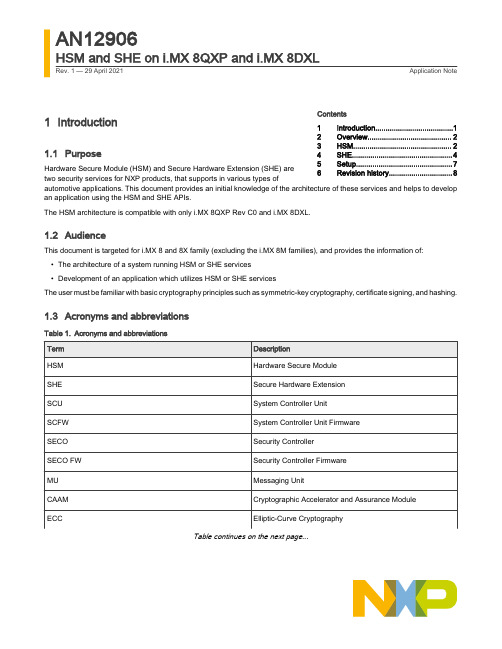
1Introduction1.1Purpose Hardware Secure Module (HSM) and Secure Hardware Extension (SHE) aretwo security services for NXP products, that supports in various types ofautomotive applications. This document provides an initial knowledge of the architecture of these services and helps to develop an application using the HSM and SHE APIs.The HSM architecture is compatible with only i.MX 8QXP Rev C0 and i.MX 8DXL.1.2AudienceThis document is targeted for i.MX 8 and 8X family (excluding the i.MX 8M families), and provides the information of:•The architecture of a system running HSM or SHE services•Development of an application which utilizes HSM or SHE servicesThe user must be familiar with basic cryptography principles such as symmetric-key cryptography, certificate signing, and hashing.1.3Acronyms and abbreviationsTable 1.Acronyms and abbreviationsTable continues on the next page...Contents 1Introduction......................................12Overview.. (23)HSM (24)SHE (45)Setup...............................................76Revision history...............................8AN12906HSM and SHE on i.MX 8QXP and i.MX 8DXLRev. 1 — 29 April 2021Application NoteOverview Table 1.Acronyms and abbreviations (continued)2OverviewHSM and SHE are the two Security Controller Firmware (SECO FW) components that are accessed by using the seco_libs API and provides security features to various kinds of applications. HSM is developed to support V2X use cases and SHE is an implementation of the SHE specification which provides security features to automotive applications. SHE is part of the baseline SECO FW available on all i.MX 8 and 8X family (excluding the i.MX 8M families), and HSM is an optional extension to these services. The presence of the HSM extension does not impact the availability of all the other baseline services.Security Controller (SECO) runs on a dedicated M0+ core. It handles critical security tasks on behalf of the rest of the system, with which it communicates using MUs.System Controller Unit (SCU) runs on a dedicated M4 core and configures the platform at start-up. It also manages the available resources for the Arm Cortex-A and Cortex-M cores.3HSM3.1ArchitectureThe architecture of HSM depends on the system on which it is deployed and the location where the user accesses the HSM services. HSM is composed of a SECO FW component and a series of additional OS-independent components that must be ported to the environment in which the user accesses the HSM services. Porting of these components has already been done for the NXP Linux distribution to demonstrate HSM usage. The architecture described in this document and schematized in Figure 1, refers to this HSM demonstrator on Linux running on i.MX 8QXP Rev C0.The architecture of the HSM demonstrator on Linux comprises four main components:•The HSM services provided by SECO. These additional services are offered alongside the baseline services inside the SECO FW.•The HSM kernel driver integrated in the Linux BSP. It is used to access the MUs that allows the communication between the users core and SECO.•The HSM storage manager. It provides storage services to SECO to preserve persistent data across power cycles. In this case, the storage manager provides the services through the Linux file system driver. The user can choose to modify the storage manager abstraction layer to support a different type of non-volatile storage and the methods to access it.•The HSM Lib. It provides the HSM features API to the user application.During HSM communication between the user core and SECO, MUs support only the control channel. The datachannel is represented by a memory partition shared between the user core and SECO, which the two can access independently.Figure 1.HSM architecture3.2ServicesAll the HSM operations (in yellow in Figure 2) are accessed using a handle (in blue in Figure 2) related to the services available.Services are organized hierarchically (as in Figure 2), that is, to open a new child service, the handle of the parent service is required. For example, to open a Cipher service to perform encryption/decryption, the user must provide the handle of an open Key Store service.The first handle is required to identify an open session with HSM. The services for Signature Verification, Hashing, and RNG can be open by using a session handle without authentication. To open a Key Store service, authentication request is required that is based on the Domain ID (DID), MU ID, the user-provided Key Store identifier, and related nonce.The hardware-level authentication is based on the DID and MU ID that allows only a user running on the expected core and using the correct MU to perform operations. The provided nonce assures that the SECO cannot access the key store content without a valid user request. Ensure to setup the platform partitioning by assigning a unique DID to each core and provide each domainthe exclusive access to its MU. The authentication is performed only once, during the opening of the Key Store service. If the authorization is successful, the Key Store handle is returned and the user can access all the operations and child services of the Key Store.For any key store present inside HSM, only one Key Store handle can be provided to the user.All the HSM operations that involve a secret, such as Key Management, Ciphering, Signature Generation, Secure Data Storage,and MAC are accessed through the Key Store.Figure 2.Services and related operation offered by HSM3.3Non-Volatile Memory (NVM) managerThe NVM manager is a user-space component of HSM used by the SECO HSM services to store permanent data across power cycles. SECO does not have direct access to permanent storage, therefore it relies on an external source to support this feature. Data is stored as encrypted blobs, in the non-volatile storage that the user decided to support in the abstraction layer of the NVM manager. The NVM manager must be only one on the system, it is subordinated to SECO requests and there is no specific domain in which it should run. In the provided example, the NVM manager is launched as a separate thread on the Cortex-A core having an underlying Linux distribution, which provide the file system driver used to store the encrypted blobs as files in the root partition.3.4Partitioning the domains on the boardFor successful authentication during the opening of the Key Store service, the request must have the correct DID, MU ID, and TZ setting. The user must address the following characteristics to correctly partition the system resources.1.Each core (for example, M4)/core cluster (for example, core-A cluster) in the system is associated with a unique DID2.Each of the 4 MUs used by SECO, need to be associated to one domain (for example, MU0 to SCU, MUx to M4, MUyto the core-A cluster, and so on)This setup is performed by the SCU and can be tuned by the user by modifying the board_system_config routine inside theboard.c file of the SCU FW.between the user and the SECO. This can also be done in the board_system_config routine inside the board.cfile or by using the SCFW API.4SHE4.1ArchitectureSimilar to HSM, the architecture of SHE depends on the platform on which it is deployed and on the location where the user accesses the SHE services. SHE is composed of a SECO FW component and a series of additional OS-independent components that must be ported to the environment in which the user accesses the HSM services. A porting of these components hasbeen already done for the NXP Linux distribution to demonstrate SHE usage. The architecture described in this document and schematized in Figure 3, refers to this SHE demonstrator on Linux running on i.MX 8QXP Rev C0.The architecture of SHE Linux demonstrator includes four main components as shown in Figure 3:•The SHE services provided by SECO. It is a part of the baseline SECO FW.•The SHE kernel driver integrated in the Linux BSP. It is used to access the MU that allows the communication with SECO.•The SHE storage manager. It provides storage services to SECO to preserve persistent data across power cycles. The storage manager provides such services through the file system driver of the OS on which it is deployed.•The SHE Lib. It provides the user application access to SHE features.The MU is used only for communication between the User Domain and SECO for control, and the data isexchanged using a shared memory partition.Figure 3.SHE architecture SECO releases prior to 2.6.x are not suitable to support production SHE implementations.4.2ServicesSHE services are limited with respect to HSM and are accessed using the same session handle as shown in Figure 4. When opening a session, an authentication is performed based on the DID, MU ID, a SHE storage identifier and the related password.The SHE storage identifier and the related password are provided by the user during the creation of the SHE storage. The SHE storage is unique in the system and always must be created before calling any other SHE API.Using a session handle it is possible to perform message authentication using AES-CMAC, key management (storage, deletion and update of internal keys), encryption and decryption using AES in ECB or CBC mode, and random number generation.Message authentication and encryption/decryption are performed by using internal non-volatile keys. These keys, namedKEY_<n> (where n is a number from 1 to 10, with possible extensions to support up to 50 keys), can be used for only one function,and can be selected at the time of loading between message authentication and encryption/decryption.The SHE SECRET_KEY and PRNG_KEY are stored respectively in the first and second half of the "SECO SECRET 2" e-fuse.This fuse must be provisioned by the OEM using SCFW API or u-boot. To locate the e-fuse's index on a specific platform, see theSecurity reference manual.Figure 4.Handle and related services offered by SHE4.3SHE Storage managerThe SHE storage manager allows SECO to store permanent data across power cycles in the form of encrypted blobs. Thestorage manager is OS independent and depends on an abstraction layer that the user must modify to support the desired type of non-volatile storage. As the HSM NVM manager, it needs to be unique in the system and can be run in the user-preferred domain (A-core cluster, M4, or SCU). In the provided Linux demonstrator, the storage manager is run as a separate thread in the Linux OS running on the A-core cluster, using the file system API to support non-volatile storage inside the root partition.4.4Partitioning the domains on the boardSHE uses the same authentication mechanism of HSM to provide access to key storage. The authentication mechanism is based on identifying a user request, firstly by its DID and MU ID, and then on a provided storage ID and password. To set up the board to securely access SHE services, the user needs to:•Assign to each core/core-cluster a unique DID•Associate each of the four SECO MUs to one core/core-clusterThis setup is performed by the SCU and can be tuned by the user modifying the board_system_config routine inside the board.c file of the SCU FW.To exchange the data during SHE operations it is required that a DDR memory area is shared between the user and the SECO. This can also be done in the board_system_config routine inside the board.c file or by using the SCFW API.5SetupThe setup provided aims at creating a system supporting both HSM and SHE to run the two examples described in the following paragraphs. The HSM architecture is only compatible with i.MX 8QXP Rev C0 and i.MX 8DXL. The following steps describe setting up of the system with the correct Linux BSP containing the SECO HSM drivers and HSM-compatible SECO FW.e Yocto to create the bootable SDCARD with the Linux distribution based on 5.4.70-2.3.0:$: mkdir <work>$: cd <work>$: mkdir <release>$: cd <release>$: repo init -u https:///external/imx/imx-manifest -b imx-linux-zeus -mimx-5.4.70-2.3.0.xml$: repo sync2.Setup the build directory selecting your <machine> between imx8qxpc0mek and imx8dxlevk:$: MACHINE=<machine> DISTRO=fsl-imx-wayland source ./imx-setup-release.sh -b<hsm_build_directory>3.Add development features to the build, by inserting the following two lines in the file <release>/<hsm_build_directory>/conf/local.conf :EXTRA_IMAGE_FEATURES_append = " dev-pkgs tools-sdk tools-debug "IMAGE_INSTALL_append = " git "unch the build:$: bitbake imx-image-core5.Flash the bootbale SDCARD file, by substituting /dev/sdX with the device name of your SD CARD:$: bzcat tmp/deploy/images/<machine>/imx-image-core-<machine>.wic.bz2 | sudo dd of=/dev/sdXbs=1M conv=fsync && sync6.Boot the board from SD card and execute the following steps from the target. Install seco_libs userspace libraries:$: cd <work>$: git clone https:///NXP/imx-seco-libs.git$: cd imx-seco-libs$: git checkout imx_5.4.70_2.3.0$: make install5.1HSM example applicationAn example program is provided with this application note to exercise the HSM features on a platform that meets the requirement of the setup described in the previous section. The example illustrates how to launch the NVM manager, create a key store, internally generate an AES key, and use it to encrypt and decrypt user-provided data.Retrieve the example code inside the imx_sec_apps repository containing other security related projects:$: git clone https:///external/imxsupport/imx_sec_apps.git$: cd imx-sec-apps/hsm_she_examplesRevision history In the Makefile, enter the location of seco_libsSECO_LIBS_DIR = <work>/imx-seco-libsCompile and launch the example:$: make all DEBUG=y$: ./hsm_test [-n or –-no-create] [keystore_identifier]Launch the application with -n or --no-create flag when a key store has already been created. Optionally, provide a key store identifier in the form of a 32bits hex, otherwise a default one will be used. If the user wants to clean the NVM state, then delete the related files used by the HSM Linux demonstrator (as below), followed by a board reset:$: rm -rf /etc/seco_hsmSee the README available here, which contains further details on the available option and the operations performed during the example.5.2SHE example applicationAn example program is provided to show the usage of the SHE APIs. The example illustrate how to launch the SHE storage manager, create an empty SHE storage, load a key, and use it for encryption and decryption user-provided data.Retrieve the example code from the same repository containing the HSM example described in the previous section. Compile and launch the example:$: make all DEBUG=y$: ./she_test [-n or –-no-create]Launch the application with -n or --no-create .If the user wants to clean the NVM state, then delete the related files used by the SHE Linux demonstrator (as below), followed by a board reset:$: rm -rf /etc/seco_she_nvmThe repository containing the SHE example is the same as that containing the HSM example. Therefore, see to the indications in HSM example application to clone and compile the example. Also, see the README in the same repository to discover further details on the performed operations.6Revision historyTable 2.Revision historyHow To Reach Us Home Page: Web Support: /support Information in this document is provided solely to enable system and software implementers to use NXP products. There are no express or implied copyright licenses granted hereunder to design or fabricate any integrated circuits based on the information in this document. NXP reserves the right to make changes without further notice to any products herein.NXP makes no warranty, representation, or guarantee regarding the suitability of its products for any particular purpose, nor does NXP assume any liability arising out of the application or use of any product or circuit, and specifically disclaims any and all liability, including without limitation consequential or incidental damages. “Typical” parameters that may be provided in NXP data sheets and/or specifications can and do vary in different applications, and actual performance may vary over time. All operating parameters, including “typicals,” must be validated for each customer application by customer's technical experts. NXP does not convey any license under its patent rights nor the rights of others. NXP sells products pursuant to standard terms and conditions of sale, which can be found at the following address: /SalesTermsandConditions.Right to make changes - NXP Semiconductors reserves the right to make changes to information published in this document, including without limitation specifications and product descriptions, at any time and without notice. This document supersedes and replaces all information supplied prior to the publication hereof.Security — Customer understands that all NXP products may be subject to unidentified or documented vulnerabilities. Customer is responsible for the design and operation of its applications and products throughout their lifecycles to reduce the effect of these vulnerabilities on customer’s applications and products. Customer’s responsibility also extends to other open and/or proprietary technologies supported by NXP products for use in customer’s applications. NXP accepts no liability for any vulnerability. Customer should regularly check security updates from NXP and follow up appropriately. Customer shall select products with security features that best meet rules, regulations, and standards of the intended application and make the ultimate design decisions regarding its products and is solely responsible for compliance with all legal, regulatory, and security related requirements concerning its products, regardless of any information or support that maybeprovidedbyNXP.NXPhasaProductSecurityIncidentResponseTeam(PSIRT)(************************) that manages the investigation, reporting, and solution release to security vulnerabilities of NXP products.NXP, the NXP logo, NXP SECURE CONNECTIONS FOR A SMARTER WORLD, COOLFLUX,EMBRACE, GREENCHIP, HITAG, ICODE, JCOP, LIFE, VIBES, MIFARE, MIFARE CLASSIC, MIFARE DESFire, MIFARE PLUS, MIFARE FLEX, MANTIS, MIFARE ULTRALIGHT, MIFARE4MOBILE, MIGLO, NTAG, ROADLINK, SMARTLX, SMARTMX, STARPLUG, TOPFET, TRENCHMOS, UCODE, Freescale, the Freescale logo, AltiVec, CodeWarrior, ColdFire, ColdFire+, the Energy Efficient Solutions logo, Kinetis, Layerscape, MagniV, mobileGT, PEG, PowerQUICC, Processor Expert, QorIQ, QorIQ Qonverge, SafeAssure, the SafeAssure logo, StarCore, Symphony, VortiQa, Vybrid, Airfast, BeeKit, BeeStack, CoreNet, Flexis, MXC, Platform in a Package, QUICC Engine, Tower, TurboLink, EdgeScale, EdgeLock, eIQ, and Immersive3D are trademarks of NXP B.V. All other product or service names are the property of their respective owners. AMBA, Arm, Arm7, Arm7TDMI, Arm9, Arm11, Artisan, big.LITTLE, Cordio, CoreLink, CoreSight, Cortex, DesignStart, DynamIQ, Jazelle, Keil, Mali, Mbed, Mbed Enabled, NEON, POP, RealView, SecurCore, Socrates, Thumb, TrustZone, ULINK, ULINK2, ULINK-ME, ULINK-PLUS, ULINKpro, μVision, Versatile are trademarks or registered trademarks of Arm Limited (or its subsidiaries) in the US and/or elsewhere. The related technology may be protected by any or all of patents, copyrights, designs and trade secrets. All rights reserved. Oracle and Java are registered trademarks of Oracle and/or its affiliates. The Power Architecture and word marks and the Power and logos and related marks are trademarks and service marks licensed by .© NXP B.V. 2020-2021.All rights reserved.For more information, please visit: Forsalesofficeaddresses,pleasesendanemailto:**********************Date of release: 29 April 2021Document identifier: AN12906。
特斯拉电动汽车用户手册说明书
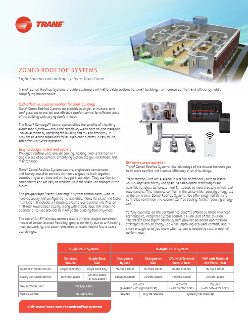
visit /zonedrooftopsystemsEf fi cient system operationTrane® Zoned Rooftop Systems take advantage of the newest technologies to improve comfort and increase ef fi ciency in small buildings.Trane rooftop units are available in a range of ef fi ciency tiers to match your budget and energy use goals. Variable-speed technologies areavailable to adjust compressor and fan speeds to more precisely match load requirements. This improves comfort in the space while reducing energy use at the same time. Zoned Rooftop Systems also offer integrated demand-controlled ventilation and economizer free cooling, further reducing energy use.To fully capitalize on the performance bene fi ts offered by these advanced technologies, integrated system control is a vital part of the solution. The Tracer® Concierge™ control system provides advanced optimization strategies to reduce energy use while improving occupant comfort, and is smart enough to let you know when service is needed to sustain optimal performance.Cost-effective, superior comfort for small buildingsTrane® Zoned Rooftop Systems are available in single- or multiple-zone con fi gurations to provide cost-effective comfort control for different areas of the building with varying comfort needs.The Tracer® Concierge™ control system offers the bene fi ts of a building automation system—without the complexity—and goes beyond managing individual rooms by operating the building smartly and ef fi ciently. It provides advanced capabilities for multiple-zone systems, is easy to use, and offers worry-free operation.Easy to design, install, and operatePackaged rooftop units provide cooling, heating, and ventilation in a single piece of equipment, simplifying system design, installation, and maintenance.Trane® Zoned Rooftop Systems use pre-engineered components and factory-installed controls that are designed to work together, contributing to on-time and on-budget installation. They use familiar components and are easy to recon fi gure if the space use changes in the future.The pre-packaged Tracer® Concierge™ system control panel, with its auto-discovery and con fi guration capabilities, allows for easier and faster installation. It includes an intuitive, easy-to-use operator interface on a 10-inch touchscreen display, along with mobile apps that allow the operator or service provider to manage the building from anywhere.The use of Air-Fi® Wireless controls results in faster project completion, increased sensor location fl exibility, greater reliability due to self-healing mesh networking, and easier relocation to accommodate future space use changes.ZO N E D R O O F TO P S YS T E M SLight commercial rooftop systems from TraneTrane® Zoned Rooftop Systems provide customers with affordable options for small buildings, to increase comfort and ef fi ciency, whilesimplifying maintenance.VAV terminal units (200 to 8000 cfm)• Trane fl ow ring provides unmatched air fl ow measurement accuracy and control • Durable, heavy-gauge air valve cylinder• modulating control• Air-Fi® Wireless communications • Retro fit dampers available for upgrading existing systemsTrane - by Trane Tech nologies (NYSE: TT), a global climate innovator - creates comfortable, energy efficient indoor environments for commercial and residential applications. For more information, please visit or .Trane h as a policy of continuous product and product data improvement and reserves th e righ t to ch ange design and specifications without notice. We are committed to using environmentally conscious print practices.All trademarks referenced are the trademarks of their respective owners.©2020 Trane. All Rights Reserved. ENV-SLB024C-ENNovember 5, 2020•single piece of equipment• able-speed fan control• Three tiers of effi ciency: standard, high, or ultra-high•••Pre-programmed, factory-installed ReliaT el™ DDC controls with wired or Air-Fi® Wireless communicationsAir-Fi® Wireless controls• Eliminates wires between equipment controllers and zone sensors, and between equipment and system controllers, allowing for faster installation, increased location fl exibility, and easier relocation• Self-healing wireless mesh and extended signal range maximize reliability• Supports open communication protocols through conformance with ASHRAE® Standard 135 (BACnet®/ZigBee®)• Up to four sensing functions in one zone sensor: temperature, humidity, occupan-cy, and CO 2• 15-year lifetime batteries。
AADvance培训手册中文版
AADvance培训⼿册中⽂版系统培训⼿册操作系统构建配置编程排除故障维护AADvance可编程控制器指南1.5版本2012年5⽉2AADvance System Training Manual, version 1.5注意The content of this document is confidential to ICS Triplex and their partners. This document contains proprietary information that is protected by copyright. All rights are reserved. No part of this documentation may be reproduced or transmitted in any form or by any means, electronic or mechanical, including photocopying and recording, for any purpose, without the express written permission of ICS Triplex.该⽂件内容对于ICS Triplex和他们的合作⽅均是机密的。
本⽂档包含有受版权保护的专有信息,公司保留其所有权。
没有ICS Triplex明确的书⾯许可,本⽂档的任何部分都不允许以任何电⼦或机械的形式或⽅式被复制和传播,包括复印和记录。
The information contained in this document is subject to change without notice. The reader should, in all cases, consult ICS Triplex to determine whether any such changes have been made.本⽂档所包含信息可以随时更改,不另⾏通知。
信息化五级架构标准
信息化五级架构标准In today's digital age, the five-level architecture standard for information technology is crucial for the development and implementation of complex IT systems. 近年来,信息技术的发展日新月异,信息化五级架构标准对于复杂IT系统的开发和实施至关重要。
This standard provides a clear framework for organizing and managing IT resources effectively, ensuring optimal performance, security, and scalability. 这一标准为有效组织和管理IT资源提供了清晰的框架,确保了最佳的性能、安全性和可扩展性。
By adhering to the five-level architecture standard, organizations can streamline operations, enhance productivity, and adapt to changing technological landscapes. 遵循五级架构标准,组织可以简化运营,提高生产力,并适应不断变化的技术环境。
The first level of the five-level architecture standard is infrastructure, which encompasses the physical components necessary to support IT operations. 五级架构标准的第一级是基础设施,包括支持IT运营所需的物理组件。
This level includes servers, storage devices, networks, and other hardware essential for data processing and communication. 这一级别包括服务器、存储设备、网络和其他对数据处理和通信至关重要的硬件。
- 1、下载文档前请自行甄别文档内容的完整性,平台不提供额外的编辑、内容补充、找答案等附加服务。
- 2、"仅部分预览"的文档,不可在线预览部分如存在完整性等问题,可反馈申请退款(可完整预览的文档不适用该条件!)。
- 3、如文档侵犯您的权益,请联系客服反馈,我们会尽快为您处理(人工客服工作时间:9:00-18:30)。
The System-Level Simplex Architecture forImproved Real-Time Embedded System SafetyStanley Bak,Deepti K.Chivukula,Olugbemiga Adekunle,Mu Sun,Marco Caccamo,Lui ShaDepartment of Computer ScienceUniversity of Illinois at Urbana-ChampaignUnited States of America{sbak2,dchivuk2,oadekunl,musun,mcaccamo,lrs}@AbstractEmbedded systems in safety-critical environments demand safety guarantees while providing many useful services that are too complex to formally verify or fully test.Existing application-level fault-tolerance methods,even if formally verified,leave the system vulnerable to errors in the real-time operating system(RTOS),middleware,and micropro-cessor.We introduce the System-Level Simplex Architecture, which uses hardware/software co-design to provide fail-operational guarantees for both logical application-level faults,as well as faults in previously dependent layers including the RTOS and microprocessor.We also provide an end-to-end design process for the System-Level Simplex Architecture where the AADL architecture description is automatically constructed and checked and the VHDL hard-ware code is generated.To show the efficacy of System-Level Simplex design,we apply the approach to both a classic inverted pendulum and a cardiac pacemaker.We perform fault-injection tests on the inverted pendulum design which demonstrate robustness in spite of software controller and operating system faults.For the pacemaker,we contrast the provided safety guarantees with those of a previous-generation pacemaker.1.IntroductionEmbedded systems are growing in complexity and must continue to meet requirements including reliability and per-formance.Reliability is difficult to scale using traditional designs because large systems have high complexity,and high complexity presents more possibilities for errors.High performance,on the other hand,drives system complexity upward.One way to deal with complex systems in a safety-critical environment is through the Simplex Architecture[1]–[4]. This architecture provides an application-level safety guar-antee by“using simplicity to control complexity”.It uses a simple safety controller subsystem to ensure the stability of the plant.This conservative safety control core is then complemented by a high-performance complex control sub-system.A decision module then uses the high-performance complex controller whenever possible,but will switch to the safety controller when system liveliness is jeopardized.This design has been applied to improve the safety of a diving controller[5],afleet of remote-controlled cars[4],and a set of advanced aircraft maneuvers[6].One drawback of the Application-Level Simplex Archi-tecture,however,is that bugs present in the microprocessor, Real-time Operating System(RTOS)or middleware,or re-sultant from their upgrades,are not guaranteed to be handled safely.Although great progress has been made towards producing a verifiable RTOS[7],most current RTOSes have been neither formally verified nor exhaustively tested.We would still like to use the services provided by an RTOS, without requiring its correctness to guarantee system safety. We thus propose the System-Level Simplex Architecture, which provides robustness in the presence of both bugs in the application and bugs in previously dependent layers such as the RTOS.In this new architecture,we perform hard-ware/software partitioning on the Simplex framework.Two Simplex safety-critical components,the safety controller and decision module,are moved to a dedicated processing unit, not for the typical HW/SW co-design reasons of power and performance,but instead to provide isolation from software-related complexity.Additionally,this architecture meets the temporal constraints of the monitored safety properties by design.Using Simplex preserves safety in the presence of logical faults,but only if Simplex is properly designed and implemented.To address proper design,we provide an AADL-based[8]System-Level Simplex architecture generator and checker.If the AADL architecture model contains an improper application of System-Level Simplex, our checker determines exactly where the violation occurs and notifies the user.We describe several necessary conditions for proper System-Level Simplex Architecture design,and for each provide an example of a safety violation that may occur if it is ignored.To address proper implementation,we extract the safety controller and decision module behaviors(which are the two simpler15th IEEE Real-Time and Embedded Technology and Applications Symposiummodules in the Simplex system)from the AADL model provided in the AADL behavior annex[9].These behavior descriptions can be expressed and formally verified in model checking tools such as UPPAAL[10].The creation of thesefinite-state machines and their safety model checking are application-specific,and a responsibility of the designer.However,if such afinite-state machine description is provided,we can use our VHDL code generator to immediately create the associated hardware code for the safety core.In brief,the key contributions of our work are:•The design of the System-Level Simplex Architecture which can handle a superset of the failure modes of previous Simplex versions•An end-to-end design process that both verifies a valid System-Level Simplex AADL architecture model and can generate hardware VHDL code from afinite-state machine description•Empirical verification of both the practicality of end-to-end System-Level Simplex design,and the robustness guarantees through fault-injection testing in two case studiesWefirst briefly review Simplex and describe the System-Level Simplex Architecture in Section2.This design pro-vides resilience from failures caused by the operating system or middleware as well as logical errors in complex control software.In Section3,we describe the end-to-end System-Level Simplex design process.This process consists of an AADL architecture generator and verifier,as well as a VHDL code generator.We then apply the architecture in two case studies in Section4.In thefirst,we examine pacemaker design and contrast the failures handled by the System-Level Simplex Architecture pacemaker with a previous-generation pacemaker.Then we apply the System-Level Simplex Architecture to an inverted pendulum system and verify its robustness with fault-injection testing.We then discuss related work in Section5and conclude in Section 6.2.System-Level Simplex DesignThe System-Level Simplex Architecture is based on the original Simplex concept[1].Simplex is logically divided into three subsystems:safety,complex,and decision(Figure 1).The safety subsystem has a simple,reliable controller which provides verifiably safe performance.This is used in case the complex controller malfunctions.The complex controller drives the system as long as it does not jeop-ardize system liveliness.This controller can be changed and upgraded while the system is running and may even contain bugs.The decision subsystem chooses which of the two previously-mentioned controllers to use.Thedecision Figure1.In the logical view of the Simplex architecture, the decision module chooses the controller version that drives the system.module and safety controller make up the trusted computing base,and must function correctly for the system to remain safe,while most of the system’s complexity is contained within the complex controller.Previous Simplex designs had all three subsystems located at the application-level.This worked well for protecting the system from value faults from the complex controller, however it required that,to guarantee system safety,the middleware,the operating system,and the microprocessor be fully reliable.We relax this requirement in the System-Level Simplex architecture by performing hardware/software partitioning on the system.The two Simplex safety-critical components,the safety controller and the decision module, are moved into a dedicated processing unit outside the microprocessor.This is akin to hardware/software co-design,except that we perform this move not primarily for reasons of perfor-mance and power consumption,but instead to protect from software-related faults.The designer therefore has a choice of what the dedicated processing unit should be.One option is to use a microcontroller to run the two safety core subsys-tems.However,in safety-critical systems,even processors are not completely trusted[11],and we would prefer to eliminate this underlying complexity.We instead choose to run the Simplex safety core on dedicated hardware. Ideally we would produce an Application-Specific Integrated Circuit(ASIC),but instead,for cost and reprogrammability reasons,we opted to perform our evaluation using a Field Programmable Gate Array(FPGA).The same VHDL code used to program an FPGA can be used to produce an ASIC. By moving the Simplex safety core to isolated hardware, we can also provide temporal correctness for the monitored safety properties.If the high-performance complex subsys-tem does not produce a control command in the appro-priate time,whether caused by an RTOS bug,poor cache performance or excessive bus contention,the conservative safety controller’s output is used.Since the safety controller runs in parallel on isolated hardware(which prevents run-time variations caused by resource sharing),the temporal constraints are met by design.2.1.Fault ModelThe System-Level Simplex Architecture tolerates two broad categories of faults:logical faults and resource sharing faults.Logical faults occur when the complex controller passes an unsafe value to the decision module,or a value of an incorrect type.One cause for this sort of fault is a mal-functioning complex controller.An incorrectly-typed value, on the other hand,may cause logical operations that use it to fail.For example,if the control commands are IEEE floating-point values that correspond to voltages,the values NAN or infinity are incorrectly-typed.Another logical fault occurs when a non-functional complex controller does not output any value.Resource sharing faults are caused by failures in common resources among components.The original Application-Level Simplex Architecture shares several resources,each of which can cause the system to fail.These include all the physical and logical resources managed by the OS like memory,CPU,and shared libraries.These faults can manifest directly(a misimplemented library causing the de-cision module process to crash),or indirectly(a mismanaged processor causing timing faults).Additional shared resources may include the communication bus and the power source. There also exist out-of-scope faults which System-Level Simplex does not address.Specifically,the sensors and actuators used by our system must be reliable and accurate. The FPGA hardware,which runs our Simplex safety core, is assumed to be correctly manufactured.Additionally,the synthesis process,which takes our VHDL code and gener-ates FPGA bitstreams,is unaddressed.However,these faults are rare since companies strive to provide reliable hardware and synthesis tools,and may be even further reduced by techniques like triple modular redundancy(TMR)[12].We also do not handle environmental modeling faults which can be present in any system that uses formal methods.Since model checking is performed on the models and not the physical environment,a significant mismatch between the two results in an unsafe system,even if it is fully model checked.To account for these errors,the formal model should be reviewed,and fault-injection testing should still be performed on thefinal system.3.System-Level Simplex Design ProcessWe now present the end-to-end design process for creating a System-Level Simplex design.The process begins with the designer providing a behavioral specification of the Simplex safety core(the safety controller and the decisionmodule)Figure2.The end-to-end System-Level Simplex design process results in a verified behavior and a validated architecture.and a logical architectural description.The behavioral spec-ification is then formally verified to meet the application-specific safety requirements.One way to do this is by model checking afinite-state machine controller against safety properties also expressed asfinite-state machines.After the behavior satisfies all safety requirements,we automatically transform the provided AADL architecture to a System-Level Simplex design.The designer can then modify the architecture to meet design-specific goals.To make sure the modifications do not result in an unsafe architecture,we pro-vide a tool to assist the validation of the architecture,which checks a set of necessary safety requirements.Violations are reported back to the designer,who can then address each one.The process is summarized in Figure2.For creating and verifying the System-Level Simplex architecture design,we use the AADL architecture descrip-tion language[8].This language is specifically designed to model the interaction of hardware and software for real-time and safety-critical embedded systems with the potential to support formal methods and the use of engineering mod-els.Several organizations,including Boeing,the US Army, and SEI have evaluated using an architecture description language as the primary modeling notion for system-level analysis.One project by the US Army reported an estimated 50%man-hour savings in the reengineering effort required to upgrade an existing missile guidance system to run on a new hardware platform[13].Similarly,our design process can be used to reengineer an existing Application-Level Simplex design into a System-Level Simplex design.In the following sections,we describe each of the steps for creating a System-Level Simplex design in detail,and our contributions in automating the pro-cess.We used the OSATE[14]environment to cre-ate and validate our AADL models because of its sup-port for both high-level logical design and low-level sys-tem properties.All of our tools are available for down-load at https:///display/ realTimeSystems/System+Level+Simplex.Figure 3.UPPAAL can be used to perform model checking on safety properties.3.1.Initial Logical DesignThe first step of the design process is to create the initial logical design using the classic Simplex paradigm.Our logical Simplex design for a cardiac pacemaker is shown in Figure 4.There are three threads cc ,sc ,dm for the complex controller,simple controller,and decision module,respectively.The sensor data are EKG signal events that detect when the heart’s ventricle or atrium has paced.The actuation signals tell whether to send a shock to the ventricle or atrium through the pacemaker leads.There is also an extra sensor signal for the patient’s acceleration that the complex controller uses to perform rate-adaptive pacing.The specification of the logical design describes each thread’s behavior using the AADL Behavior Annex [9].The Behavior Annex describes behavior with message passing finite-state machines.This behavioral model can be trans-lated to an equivalent specification in a model checking tool such as UPPAAL [10].The UPPAAL model of the pacemaker behavior is shown in Figure 3.UPPAAL is then used to formally verify safety properties for the logical Simplex design.3.2.System-Level Simplex Architecture GenerationWe have created an OSATE plug-in that inputs the for-mally verified logical design from before,and automatically generates the general structure of the System-Level Simplex Architecture.The logical design in Figure 4is transformed into the System-Level design shown in Figure 5.The transformation wraps the individual threads into sep-arate processes that have isolated memory and processors.Furthermore,all communication from the complex controller is put inside an application-level process.The pseudo code for the hardware design generation is shown in Code Block1.Figure 4.The design process takes in a logical Simplex AADLModel.Figure 5.The design process generates a System-Level Simplex AADL Model.3.3.System-Level Simplex Architecture ValidationWe have also produced a System-Level Simplex archi-tecture checker which will traverse an AADL model and enforce a checklist of architectural requirements.This is important because the generator does not provide a one-size-fits-all architecture,but rather an application-specific template that is further modified for the specific design.We want to guarantee that these further modifications do not violate key Simplex architectural safety requirements.We have identified several necessary conditions required by a System-Level Simplex design that are checked by our OSATE architecture checker.The properties can be classified into resource isolation properties,data consistency properties,and data flow properties.We briefly describe each of these,along with associated failures that may occur if they are not present.Resource isolation properties that we require include a real-time bus with an electrically-safe interface (such as the CAN bus [15]),and a power management scheme.If the bus is not real-time,correct complex controller commands may not reach the decision module in a timely fashion,which will result in degraded system performance as the safety controller will be used instead.If the bus interface is not electrically safe,the FPGA hardware may be damaged bya short on the bus,which may damage the Simplex safety core.If the power is not managed,the complex controller may drain all the system’s power,shutting down the Simplex safety core.One data consistency property that we check is that the value received from the complex controller goes through a type-checking process.If this were not the case,a complex controller may send values of the wrong type(for example, sending thefloating-point value NAN instead of afinite voltage value),which the decision module may not interpret correctly.Dataflow properties impose requirements on the connec-tions among the System-Level Simplex components.The complex controller,for example,should not be sending data to the safety controller,only to the decision module.If these connection properties are not enforced,we can not guarantee that the architecture is actually an instance of Simplex. Our architecture checking tool enforces each of these necessary requirements for architectural safety.The tool can be further extended to enforce additional requirements by defining new AADL properties and writing the expected invariants on these properties.3.4.System-Level Simplex Implementation Gener-ationWe have developed a VHDL code generator to automati-cally create the System-Level Simplex hardware code for both the safety controller and decision module.If these modules are described asfinite-state machines in the AADL behavior annex,the corresponding VHDL code can be im-mediately generated.This removes an extra level of human interaction which may have lead to errors.The VHDL hardware code can then be synthesized and used to program an FPGA.4.Case StudiesIn order to demonstrate the practicality and robustness of System-Level Simplex systems,we examine two case studies in detail.First,we use our end-to-end design pro-cess to produce a cardiac pacemaker system and compare the resultant safety guarantees with those provided by a previous-generation ter,we apply the System-Level Simplex Architecture to a classic inverted pendulum and empirically verify fault-tolerance guarantees.In addition to the two case studies discussed in this paper,we are currently evaluating the System-Level Simplex design to provide safety for control of an autonomous tractor,in collaboration with John Deere.Code1The architecture generator separates the logical Simplex system into a System-Level AADL model.newModel=copy(model);ss=new SimplexSwitch(model);ss.traverseModel();//find simplex componentsappProc=newModel.wrapInProcess(plex_ctrl);sysProc=newModel.wrapInProcess(ss.simple_ctrl,ss.decision_module);...appProc.bindToMemory(appMem);appProc.bindToProcessor(cpu);sysProc.bindToMemory(sysMem)sysProc.bindToProcessor(fpga);newModel.bindPower(power_source);...newModel.createDataConnections(ss.conn);newModel.createBusBindings(sysBus);...return newModel;}4.1.System-Level Simplex Design for a Cardiac PacemakerA cardiac pacemaker is a piece of hardware inserted into a patient’s body in order to regulate his or her heart rate. Detailed designs of cardiac pacemakers have been disclosed [16],[17].In this safety-critical application,we examine the practicality and usefulness of the System-Level Simplex Architecture,as well as the end-to-end design process.We investigate three considerations for using the System-Level Simplex Architecture:•Can the system be divided up into a safe controller anda complex controller,such that the most likely causesof failure are contained in the complex controller?•Is the System-Level Simplex end-to-end design processeffective in the cardiac pacemaker context?•How do the resultant safety guarantees compare tothose of existing pacemakers?4.1.1.Dividing the Cardiac Pacemaker System.Thefirst concern,the division of the system into complex and simple controllers,asks if the logical Simplex framework can be applied to a cardiac pacemaker.Since this is domain-specific, we examine some properties of artificial pacemakers.Thefirst generation of artificial pacemakers actuated the heart at a set interval.This functionality was sufficient to keep the patient alive,however,problems did arise. For example,when a healthy person walks up stairs or performs strenuous action,his heart rate increases.Thefirst generation of pacemakers did not take this into account and patients would become dizzy and uncomfortable.Additional functionality was added to pacemakers to detect if the heart rate should be increased by monitoring the temperature of the blood,or the acceleration on the patient’s body[16].Requirements were then added on top of this to preserve smooth heart-rate transitions,rather than suddenly jumping from65to120beats per minute because of a sudden large acceleration.Additionally,modern pacemakers attempt to detect and log anomalous events with the heart to aid a doctor’s diagnosis.The logged data must be retrieved, and this is done through wireless communication with an external device.Modern pacemakers have many other requirements,how-ever we already covered enough to apply the System-Level Simplex Architecture.The rate-adaptive pacing modes, where the heart rate changes over time,require complex functionality.The pacing rate to which we should change is a function of the current rate,as well as the past and present accelerometer readings.The safety properties we want to enforce are that the heart rate should be between a lower rate limit and an upper rate limit,and should not change by more than a doctor-specified rate-smoothing parameter. These are the properties monitored by the decision module. The safe controller is afinite-state machine that meets the safety requirements.We choose a safe controller that slows down the heart to the resting rate(lower rate limit)in a way that satisfies the rate smoothing requirement.This safety controller does not have the complex rate-adaptive functionality,but instead provides a fail-operational mode that will maintain safety for the patient.ing the System-Level Simplex Design Process. The second concern addresses the effectiveness of the end-to-end System-Level Simplex design process.The inputs for the process are afinite-state machine behavioral description for the decision module and safety controller,and the logical AADL architecture description for Simplex.As discussed in Section3,we begin by describing both the decision module behavior and safety controller behavior asfinite-state machines.The heart is then modeled in the same way,and we exhaustively test for violations of safety properties in UPPAAL(Figure3).For example,one property we check is that the safety core will not actuate the heart unless it has been idle for a minimum time interval(to enforce a maximum heart rate),for all possible actuation commands coming from the unspecified complex controller. When this checking is complete,we describe thefinalfinite-state machines in the AADL behavior annex.The next step is the construction of the initial AADL model.This model,shown in Figure4,outlines the logical Simplex connections.Our OSATE plug-in then takes this initial model and transforms it into a model for a System-Level Simplex Architecture(Figure5).At this point the designer can modify the model as needed and run our architecture checker to make sure all System-Level Simplex Architecture requirements are met.One item checked is power safety between the Simplex safety core and the complex controller.If power is not managed,the complex controller can drain the shared battery causing the system to fail.Although the architecture checker makes sure this constraint is satisfied,the designer must determine how to satisfy it.Our pacemaker is designed as a System-on-Chip(SoC)running on a Xilinx FPGA.Modern Xilinx FPGAs have several clock regions which can be toggled on or off[18].By using a soft processor on the FPGA to run the complex subsystem,we can control the power consumed by disabling the processor’s clock when the battery is low.In CMOS circuits,preventing transistor state changes(by stopping the clock)results in near-zero power consumption.In this way we are able to provide power isolation,and can set the appropriate power-isolation AADL property within our model.Without the architecture checker,this critical step could be overlooked.After the architectural constraint checker validates the model,we proceed to generate the implementation for our pacemaker.The AADL behavior annexfinite-state machines for both the decision module and the complex controller are put into our VHDL code generator.The generator produces synthesizable hardware VHDL code which is used to program the FPGA.paring against Existing Pacemaker Reliability Mechanisms.The last consideration compares the existing reliability mechanisms found in one previous-generation pacemaker description[16]to the design created using the System-Level Simplex end-to-end design process.We focus on two mechanisms for enhanced reliability which were present in the pacemaker description we examined.Thefirst is a watchdog timer which is periodically reset during normal system execution.If the execution hangs at some point,the timer will not be reset and will timeout. The timeout triggers a high-priority interrupt which signals that an anomalous event has occurred and the system is reinitialized.Alternately,the system can be shut down as a fail-safe mechanism.The watchdog timer mechanism is compatible with the System-Level Simplex Architecture.It provides a means to restart the system when it enters a rare error state.However, the watchdog timer does not protect the system from unsafe pacing,only system hangs.Additionally,deterministic bugs in the program will continue to restart the system,whereas a System-Level Simplex system is able to function safely in spite of deterministic bugs in the complex controller.The other safety mechanism we examine is a redundant pacemaker system which,atfirst,appears to be similar to the System-Level Simplex Architecture.This system provides a simpler pacing mode without rate-adaption.This system takes control from the microprocessor when“a fault is detected in the operation of the microprocessor circuit.”This component,like the System-Level Simplex Architecture, provides protection from microprocessor errors.This is a real cause of concern with this specific pacemaker designbecause it uses a custom pacemaker-specific microprocessor. However,it does not provide protection from logical faults in the software.Additionally,control is switched to this system when any fault in the microprocessor is detected. In the System-Level Simplex Architecture,a hardware fault that only affects the logging mechanism(perhaps because of a rarely used instruction),one that does not compromise safety,would not trigger a change in control.4.2.System-Level Simplex Design for Inverted Pen-dulumAn inverted pendulum is a classical control testbed where a rod must be maintained upright by moving a cart along a track.An inverted pendulum presents an obvious failure state when the rod falls over.We applied the System-Level Simplex Architecture to an inverted pendulum and evaluated its robustness by inserting faults and observing system robustness.An inverted pendulum,however,does not completely lend itself to our end-to-end design process.We still generate the AADL architecture description and run it through the ar-chitecture checker to make sure the architectural constraints are met.However,control of an inverted pendulum is best done through differential equations rather thanfinite-state machines.This means that we can not use afinite-state ma-chine model checker such as UPPAAL to guarantee safety. Instead,we guarantee safety through the same technique as previous Simplex applications[1].We measure the inverted pendulum system andfind a Lyapunov stability function [19].From this,we can generate the safety controller C code using Matlab Simulink[20]and determine when the decision module should switch controllers(before the state leaves the Lyapunov stability neighborhood).The C code is then manually translated to VHDL for hardware synthesis. Our hardware safety core resides on an externally-powered Xilinx ML505FPGA.This FPGA contains a PCIe port which is used to communicate to a PC which runs the software portion of the architecture.The software portion uses a custom driver written for Linux.We run Linux/RK [21]as the operating system for the complex controller. Since the System-Level Simplex Architecture handles tim-ing faults,we purposefully do not use the provided real-time scheduler.Through memory-mapped I/O,the complex controller reads the most recent angle and track position and suggests a motor voltage to the hardware-based decision module.After constructing the system,we verified that the software-based complex controller was able to actuate the inverted pendulum as long as it did not jeopardize safety. When the pendulum’s state approached the edge of the Lyapunov stability neighborhood,the safety controller took over and prevented the pendulum from collapsing.In thisInverted Pendulum Fault-InjectionFailure Type SafeNoOutput√Maximum V oltage√Wrong Way—Maximum V oltage√Time Degraded Control√OS Crash√Timing Faults√Computer Reboot√T able1.The System-Level Simplex inverted pendulumtolerates a variety of faults.Figure6.When the inverted pendulum state passes the edge of the recoverable region(dashed line),the safety controller takes over and prevents system collapse.way,the system was able to tolerate a multitude of faults as outlined in Table1.We outline two of these faults in detail.4.2.1.Wrong Way—Maximum Voltage.The pendulum should remain balanced even if the complex controller outputs a motor voltage that would normally destabilize the system.This test took an extreme case of this where we used a working inverted pendulum controller for a few seconds,and then output the maximum voltage in the direction opposite of that needed to stabilize the pendulum. The decision module detected this and switched control to the safety subsystem.The safety controller returned the pendulum to a stable state and control was again given to the complex subsystem after a few seconds.Measurements from one iteration of this process are given in Figure6. puter Reboot.The System-Level Simplex Ar-chitecture provides protection from arbitrary operating sys-tem behavior,including rebooting the system.From the decision module’s perspective,the computer rebooting is equivalent to a complex controller that sends no output. We ran this test on our inverted pendulum setup,and the pendulum remained stable throughout the reboot process. Additionally,after the computer restarted,the software-based complex controller was able to regain control of the inverted pendulum using memory-mapped I/O with the。