WGL-800录波装置说明书
便携式录波仪说明书

便携式录波仪说明书目录第一章引言 (1)1.1 仪器简介 (1)1.2特性和技术参数 (1)第二章仪器组成 (3)2.1硬件组成 (3)2.2软件组成 (4)第三章仪器操作 (6)3.1 仪器启动与关闭 (6)3.2 仪器设置 (6)3.3 软件系统升级 (7)3.4 虚拟键盘 (7)3.6 通道率定 (8)3.7 试验数据导出 (9)3.8 数据保存与读取 (10)3.9 生成试验报告 (11)3.10 示波器操作 (11)3.11 运算组合分析 (14)3.12 交叉图形工具 (15)3.13 傅里叶频频分析 (16)3.14 谐波分析 (17)3.14 图形编辑 (18)3.15 有效值和交流功率计算 (19)3.16 三相分析 (19)3.17 相量图工具 (20)第四章试验模板 (22)4.2 12/8/6/交流录波试验 (22)4.2 发电机空载特性试验 (22)4.3 发电机三相短路特性试验 (24)4.4 甩负荷试验 (25)4.5 机组同期试验 (26)4.5 励磁系统10%阶跃响应试验 (27)4.6 励磁系统电压频率特性 (28)4.7 励磁系统灭磁特性 (29)第五章注意事项 (30)第六章装箱清单及联系方式....................................................................... 错误!未定义书签。
第一章引言1.1 仪器简介便携式波形记录仪是针对电力系统应用而开发的瞬态信号记录仪器,仪器内部软件预置了针对发电机调试的试验模板,使用户可以通过记录仪很方便的完成发电机短路特性试验,空载特性试验,励磁系统扰动试验,励磁系统10%阶越试验,灭磁常数测量,自准同期装置校验,机组甩负荷记录等试验。
仪器具有丰富的软件组件使用户可以通过软件组件,自由进行图形分析,组合运算,有效值计算,交流功率计算,三相对称性分析,频谱分析,谐波分析,曲线相关性分析,图形编辑和相量图绘制等操作。
wy9故障录波装置定值操作说明
国电武仪故障录波装置定值操作说明一、查看录波器定值第一步:在录波管理软件界面,点击工具栏“提取定值〞按钮。
第二步:点击工具栏“编辑定值〞按钮。
录波管理单元将录波器中的配置信息和启动定值提取到录波管理单元,并翻开定值编辑软件。
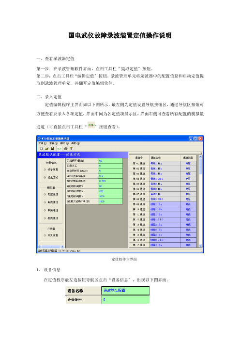
二、录入定值定值编辑程序主界面如以下图所示,最左侧为定值设置导航按钮区,通过导航区按钮可方便查看及录入各项定值,界面中间为各定值项显示区,界面右侧可查看所有配置的模拟量通道〔可直接点击工具栏“〞按钮查看〕。
定值软件主界面1、设备信息在定值程序最左边按钮导航区点击“设备信息〞,出现以下图界面:改界面可以修改设备名称,设备编号默认为0。
2、记录方式在左侧按钮导航区点击“记录方式〞,出现如下配置对话框:在该界面下可以设置AB段采样率,以及各采样段的时间。
3、模拟量通道参数及启动量配置3.1 “电压通道〞配置出厂时,电压通道号已分配好,通道名称依次定义为“第一组电压通道〞、“第二组电压通道〞……〔通道名称可修改〕,电压等级定义为220kV,PT变比定义为1200〔表示1200:1〕,所有启动量定义为不判,如以下图所示。
现场应根据定值整定通知书重新定义通道名称、电压等级、CT变比和启动值。
图电压通道参数初始配置图电压通道启动量初始配置编辑方法: 点击定值软件左侧导航区“电压通道〞按钮,然后点击中间信息区的“参数〞标签,显示如以下图的界面,在此界面中可修改电压通道名称、各相通道号以及电压等级。
点击“启动量〞标签可编辑电压通道的各项启动信息如以下图,各项参数初始值为不判。
3.2电流通道组配置出厂时,电流通道号已分配好,通道名称,依次定义为“第一组电流通道〞、“第二组电流通道〞……〔通道名称可修改〕,关联母线定义为1、CT变比定义为600、CT二次额定电流定义为5A,所有启动量定义为不判,如以下图所示。
现场应根据定值整定通知书重新定义通道名称、关联母线〔运行时对应的母线〕、CT变比、CT二次额定电流。
Extech SDL800 振动计测器用户指南说明书
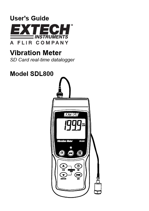
User's Guide Vibration MeterSD Card real-time dataloggerIntroductionCongratulations on your purchase of the Extech SDL800 Vibration Meter. This meter displays and stores vibration readings of Acceleration, Velocity and Displacement. Supported measurement units are meters/s2, ft/s2, g, mm/s, cm/s, in/s, mm and inch. Logged data readings are stored on an SD card for transfer to a PC. This meter is shipped fully tested and calibrated and, with proper use, will provide years of reliable service.SafetyInternational Safety SymbolsThis symbol, adjacent to another symbol or terminal, indicates the user must refer to themanual for further information.Backlight keyON-OFF keyNotes: Items listed in “10” are located behind the snap-off compartment cover on meter’s right side. Battery compartment, tilt stand, and tripod mount are located on the rear of the instrumentGetting StartedPower ON-OFF•Power the meter by pressing and holding the power button for at least 1.5 seconds.•Press and hold the power button for at least 1.5 seconds to power OFF the meter.•This meter is powered by six (6) 1.5VDC ‘AA’ batteries or by optional AC adaptor. If the meter will not switch ON please check that fresh batteries are installed in the rear battery compartment or, in the case of the AC adaptor, check that the adaptor is connected correctly to the meter and to an AC source.Display BacklightTo turn the display backlight ON or OFF, press and hold the backlight button for at least 1.5 seconds. The meter will beep when switching the backlight ON or OFF unless the beeper isdisabled.Vibration SensorConnect the vibration pickup to the cable supplied. Make sure it is firmly attached.Connect the cable to the meter by attaching it to the BNC connector on the top of the meter.If the surface to be tested is magnetic, attach the magnetic base to the vibration pickup and attach the pickup to a flat surface.If the surface to be tested is not magnetic, hold the pickup against the surface. Do not hold the cable while making measurements.Units of MeasureThe currently selected unit of measure is shown on the meter’s LCD. To change the unit ofmeasure, press and hold the UNIT button until the desired unit of measure appears and then release the UNIT button. The meter begins scrolling through the available units of measure after the UNIT button has been depressed for at least 1.5 seconds. The saved units will become the default turn-on units.INDICATORUNIT DISPLAYACCm/s2gVELmm/scm/sDISP p-p mmACC ft/s2VEL In/sDISP p-p inchFunction SelectionThe currently selected function is shown on the meter’s LCD. To change the function, press and hold the FUNCTION button until the desired function appears, then release the FUNCTION button.The available functions are:RMS: typical selection for Acceleration and VelocityPEAK: displays the peak value of the vibrationMAX HOLD: displays and holds the max value measuredMAX HOLD ResetPress and hold the ▲ and ▼ buttons for 1.5 seconds to clear the max Hold reading.Data HoldTo freeze a displayed reading on the LCD, momentarily press the HOLD button (the HOLD icon will appear above the reading). To exit HOLD, press the HOLD button again.ZERO AdjustmentThe ZERO function is used to remove any small offset caused by temperature changes or other environmental changes. The zero will only work for a display of 10 or less digits.1. Connect the vibration sensor to the meter2. Set the measurement function to Acceleration3. Make sure the sensor is motionless and not subject to any vibrations4. Press and Hold the ▼ and ▲buttons for 1.5 seconds and the meter will zeroMax-Min Reading RecordFor a given measurement session, this meter can record the highest (MAX) and the lowest (MIN) readings for later recall.1. Press the MAX-MIN button momentarily to access this mode of operation (REC icon appears)2. The meter is now recording the MAX and MIN readings.3. Press the MAX-MIN button again to view the current MAX readings (MAX icon appears). Thereadings on the display are now the highest readings encountered since the REC icon wasswitched on (when the MAX-MIN button was first pressed).4. Press the MAX-MIN button again to view the current MIN readings (MIN icon appears). Thereadings on the display are now the lowest readings encountered since the REC icon wasswitched on (when the MAX-MIN button was first pressed).5. To exit the MAX-MIN mode, press and hold the MAX-MIN button for at least 1.5 seconds. Themeter will beep, the REC-MAX-MIN icons will switch off, the MAX-MIN memory will clear, and the meter will return to the normal operating mode.Setup ModeBasic settings at a glanceTo view the current configuration of the meter with regard to time, date, and datalogging sampling rate press the SET button momentarily. The meter will now display the configuration in quicksuccession. If the information is missed on the first try, simply press the SET button again until all of the information is noted.Accessing the Setup mode1. Press and hold the SET button for at least 1.5 seconds to access the Setup menu.2. Press the SET button momentarily to step through the available parameters. The parametertype is shown on the bottom of the LCD and the current selection for that type is shown above it.3. When a parameter is displayed that is to be changed, use the arrow keys to change the setting.Press the ENTER button to confirm a change.4. Press and hold the SET button for at least 1.5 seconds to exit the Setup mode. Note that themeter automatically switches out of the Setup mode if no key is pressed within 7 seconds.5. The available Setup parameters are listed below. Additional detailed information is providedbelow this list:dAtE Set the clock (Year/Month/Date; Hours/Minutes/Seconds)SP-t Set the datalogger sampling ratePoFF Automatic power-off management (Enable or disable the auto-power off function)bEEP Set the beeper sound ON/OFFdEC Set the numerical format; USA (decimal: 20.00) or European (comma: 20,00)Sd F Format the SD memory cardSetting the Clock Time1. Access the dAtE parameter.2. Use the ENTER button to step through the selections (year, month, day, hour, minute, second)3. Use the arrow keys to change a value4. Press and hold the SET button for at least 1.5 seconds to exit to the normal operation mode (orsimply wait 7 seconds for the meter to automatically switch to the normal operating mode).5. The clock will keep accurate time even when the meter is switched off. However, if the batteryexpires the clock will have to be reset after fresh batteries are installed.Setting the Datalogger Sampling Time (Rate)1. Access the SP-t parameter.2. The sampling rate can be set to 0, 1, 2, 5, 10, 30, 60, 120, 300, 600, 1800 or 3600 seconds.3. Use the arrow keys to change the digit values.4. Press the ENTER button to confirm the entry.5. Press and hold the SET button for at least 1.5 seconds to exit to the normal operation mode (orsimply wait 7 seconds for the meter to automatically switch to the normal operating mode).Enabling/Disabling the Auto Power OFF FeaturePoFF parameter.the1. Access2. Use the arrow buttons to select ON or OFF. With the Auto Power OFF feature enabled, themeter will automatically switch OFF after 10 minutes of inactivity.3. Press ENTER to confirm setting.4. Press and hold the SET button for at least 1.5 seconds to exit to the normal operation mode (orsimply wait 7 seconds for the meter to automatically switch to the normal operating mode).Set the Beeper Sound ON or OFFbEEP parameter.1. Accessthe2. Use the arrow buttons to select ON or OFF.3. Press ENTER to confirm setting.4. Press and hold the SET button for at least 1.5 seconds to exit to the normal operation mode (orsimply wait 7 seconds for the meter to automatically switch to the normal operating mode). Numerical Format (comma or decimal)European and USA numerical formats differ. The meter defaults to USA mode where a decimal point is used to separate units from tenths, i.e. 20.00; The European format uses a comma, i.e.20,00 to separate units from tenths. To change this setting:thedEC parameter.1. Access2. Use the arrow buttons to select USA or EUro.3. Press ENTER to confirm setting.4. Press and hold the SET button for at least 1.5 seconds to exit to the normal operation mode (orsimply wait 7 seconds for the meter to automatically switch to the normal operating mode).SD Card FORMATTING1. AccessSd-F parameter.the2. Use the arrow buttons to select YES to format the card (select NO to abort). Note that all dataon the card will be lost if formatting is attempted.3. Press ENTER to confirm selection.4. Press ENTER again to re-confirm.5. The meter will automatically return to the normal operating mode when formatting is complete.If not, press and hold the SET button for at least 1.5 seconds to exit to the normal operationmode.System ResetIf the meter’s keys become inoperable or if the display freezes, the Reset button can be used to reset the instrument.•Use a paper clip or similar item to momentarily press the reset button located on the lower right side of the instrument .•After pressing the Reset button, switch the instrument ON by pressing and holding the POWER key for at least 1.5 seconds. If using the power adaptor unplug the adaptor and then plug it back in again to power the meter.DataloggingTypes of Data Recording•Manual Datalogging: Manually log up to 99 readings onto an SD card via push-button press.•Automatic Datalogging: Automatically log data onto an SD memory card where the number of data points is virtually limited only by the card size. Readings are logged at a rate specified by the user.SD Card Information•Insert an SD card (from 1G size up to 16G) into the SD card slot at the bottom of the meter. The card must be inserted with the front of the card (label side) facing toward the rear of the meter.•If the SD card is being used for the first time it is recommended that the card be formatted and the logger’s clock set to allow for accurate date/time stamping during datalogging sessions.Refer to the Setup Mode section for SD card formatting and time/date setting instructions.•European and USA numerical formats differ. The data on the SD card can be formatted for either format. The meter defaults to USA mode where a decimal point is used to separate units from tenths, i.e. 20.00. The European format uses a comma, i.e. 20,00. To change this setting, refer to the Setup Mode section.Manual DataloggingIn the manual mode the user presses the LOG button to manually log a reading onto the SD card.1. Set the sampling rate to ‘0’ seconds as described in the Setup Mode section.2. Press and hold the LOG button for at least 1.5 seconds and the DATALOGGER icon will appearon the LCD; the lower portion of the display will show p-n (n = memory position number 1-99).Note that if PSI is set as the unit of measure it appears as P51 (where a ‘5’ is used as an ‘S’) in the same area of the LCD where memory locations are shown. This can be disorienting at first.3. Momentarily press the LOG button to store a reading. The DATALOGGER icon will flash eachtime a data point is stored.4. Use the ▲ and ▼ buttons to select one of the 99 data memory positions in which to record.5. To exit the manual datalogging mode, press and hold the LOG button for at least 1.5 seconds.The DATALOGGER icon will switch off.Automatic DataloggingIn automatic datalogging mode the meter takes and stores a reading at a user-specified sampling rate onto an SD memory card. The meter defaults to a sampling rate of two seconds. To change the sampling rate, refer to the Setup Mode section (the sampling rate cannot be ‘0’ for automatic datalogging):1. Select the sampling rate in the Setup Mode to a value other than zero.2. Press and hold the LOG button for at least 1.5 seconds. The meter will flash the DATALOGGERicon at the selected sampling rate indicating that readings are now being automatically recorded to the SD card.3. If a card is not inserted or if the card is defective, the meter will display SCAN SD indefinitely. Inthis case, switch the meter OFF and try again with a valid SD card.4. Pause the datalogger by pressing the LOG button momentarily. The DATALOGGER icon willstop flashing and the sample rate will display for a short time. To resume logging simply press the LOG button again momentarily.5. To terminate the datalogging session press and hold the LOG button for at least 1.5 seconds.6. When an SD card is used for the first time a folder is created on the card and named VBD01.Up to 99 spreadsheet documents (each with 30,000 readings) can be stored in this folder.7. When datalogging begins a new spreadsheet document named VBD01001.xls is created on theSD card in the VBD01 folder. The data recorded will be placed in the VBD01001.xls document until 30,000 readings are reached.8. If the measurement session exceeds 30,000 readings, a new document will be created(VBD01002.xls) where another 30,000 readings can be stored. This method continues for up to99 documents, after which another folder is created (VBD02) where another 99 spreadsheetdocuments can be stored. This process continues in this same fashion with folders VBD03through VBD10 (last allowable folder).SD Data Card to PC Data Transfer1. Complete a datalogging session as detailed in above in the previous sections. Hint: For thefirst few tests, simply record a small amount of test data. This is to ensure that the datalogging process is well understood before committing to critical, large scale datalogging.2. With the meter switched OFF, remove the SD Card.3. Plug the SD Card directly into a PC SD card reader. If the PC does not have an SD card slot,use an SD card adaptor (available at most outlets where computer accessories are sold).4. Power the PC and run a spreadsheet software program. Open the saved documents in thespreadsheet software program (see example spreadsheet data screen below).Spreadsheet data exampleRS-232/USB PC InterfaceThe optional 407001A software kit (software and cable) allows streaming of data to a PC viathe RS232 Output jack.AC Power AdaptorThis meter is normally powered by six (6) 1.5V ‘AA’ batteries. An optional 9V power adaptor is available. When the adaptor is used, the meter is permanently powered and the power button will be disabled.Battery Replacement and DisposalWhen the low battery icon appears on the LCD, the batteries must be replaced. Several hours of accurate readings are still possible in this condition; however batteries should be replaced as soon as possible:•Remove the two (2) Phillips screws from the rear of the meter (directly above the top of the tilt stand).•Remove and safely place the battery compartment and screws where they will not be damaged or lost.•Replace the six (6) 1.5V ‘AA’ batteries observing polarity.•Replace the battery compartment cover with the two (2) Phillips screws.All EU users are legally bound by the battery ordinance to return all used batteries tocollection points in your community or wherever batteries / accumulators are sold!Disposal in the household garbage is prohibited!SpecificationsDisplay Backlit LCD; LCD size: 52 x 38mm (2 x 1.5”)Status indicators Over-range audible beep and low battery display iconFrequency Range 10Hz to 1kHzDatalogger Sampling Rate AUTO LOGGING: From 1 to 3600 seconds.MANUAL LOGGING: Set the sampling rate to ‘0’ seconds Memory Card SD memory card; 1G to 16GB sizeData Hold Freeze the displayed readingMemory Recall Record and Recall the Maximum and Minimum readingsDisplay update rate Approx. 1 secondData Output RS-232 / USB PC computer interfaceOperating Temperature 0 to 50°C (32 to 122°F)Operating Humidity 85% R.H. max.Auto Power OFF A fter 10 minutes of inactivity (can be disabled)Power Supply Six (6) 1.5 VDC batteries (optional 9V AC adaptor)Power Consumption Normal operation (backlight and datalogger OFF): approx. 5mAdcWith backlight OFF and datalogging ON: approx. 25mAdcWith backlight ON add approx. 12mAdcWeight 343g (0.75 lbs.) w/ batteries; 241g (0.53 lbs.) w/o batteriesDimensions Meter: 182 x 73 x 47.5mm (7.1 x 2.9 x 1.9”)Vibration sensor: round 16mm (0.63”) diameter, 37mm (1.46”)lengthElectrical SpecificationsFunction Unit Range Accuracym/s20.5 to 199.9 m/s2g 0.05 to 20.39 G ft/s2 2 to 656 ft/s2± ( 5%rdg + 2 d ) @ 80 and 160HzAccelerationCalibration Point: 50 m/S^2 ( 160 Hz )mm/s 0.5 to 199.9 mm/scm/s 0.05 to 19.99 cm/s inch/s 0.02 to 7.87 inch/s ± ( 5%rdg + 2 d ) @ 80 and 160HzVelocityCalibration Point: 50 mm/s ( 160 Hz )mm 1.999mm inch 0.078inch ± ( 5%rdg + 2 d ) @ 80 and 160HzDisplacementCalibration Point: 0.141 mm ( 160 Hz )Above specification tests under the environment RF Field Strength less than 3 V/M & frequency less than 30 MHz only and 23±0.5ԨCopyright © 2011 Extech Instruments Corporation (a FLIR company)All rights reserved including the right of reproduction in whole or in part in any form。
WL—8000说明书
服务器
目标 IP 网络端口
通讯协议
安装方式
外形尺寸
工作环境温度
工作环境湿度
产品重量
技术参数表 220VAC(±20%)
空载静态功率小于 5W,最大消耗功率 10W 100ms 800ms
4mA~20 mA ±0.1%
TTL 电平或干接点信号 触点容量:30VDC:1A,125VAC:0.5A,60VDC:0.3A
供电
网口
RS232 或 RS485 串口 1 RS232 或 RS485 串口 2
外部 24VDC 输入+
信号输出
第 1 路模拟量输出通道
信号地
※由于电流输出是隔离的,因此需有外部供电 24VDC。
第二章 操作指南 .............................................................................................5
2.1 设备出厂标准配件 ..................................................5 2.2 设备安装、供电 ....................................................5 2.3 通道接线说明 ......................................................5
长×宽×高(mm):482.6×200×44 -10~+50℃ 5~95%RH 约 1600g
4
KLW8000 系列数据采集器操作指南 V3.6
第二章 操作指南
2.1 设备出厂标准配件
☑主机
☑ 配套螺丝刀
故障录波讲解演示文稿
➢ 细致的分析是故障定点的关键:
线路发生故障后,尽管到达故障点的时间越短,故障检出
的成功率越高。但是,接到调电度力命线令路后发决生不短能路盲是目出地现立最即多巡
线,而应一边及时召集必要的的一事种故故巡障视形人式员。做中巡性线点的直有接关接准
备,一边利用较短的时间,地收的集电索网要中事,故以数单据相并接进地行短全路面的细
(一般按10%掌握)在台账上确定故流障增区大间较,多还。应结合以往
线路跳闸的经验数据进行部分修正。
其次应对可能的故障进行定性。这一点很重要也很难,需
要灵活运用事故数据分析、丰富的事故查找经验,掌握准确
的现场情况,并应经集体商定。根据保护及自动装置的动作
情况及反映的故障前后的电压、电流量的数值进行简单定性
分辨率不劣于1.0ms。
21
第21页,共45页。
故障录波器的通信网络:串口、MODEM、网络、微波、载 波、光纤等。
录波器联网结构图
22
第22页,共45页。
5.2 故障录波器实例-YS-88A
概述: YS-88A型微机故障录波测距装置是南京银山电子有限公司
研制的产品,目前在国内变电站中应用较为广泛。 装置采用以DSP数据采集单元为前置机,工控机为后台机
16
第16页,共45页。
采样保持器; 多路转换开关;
A/D转换器;
开关量信号的数据采集;
中央处理器(CPU)。 2、主机:主要由工控机、半导体固化盘和接口系统三大部分组成
。其中接口系统主要功能有:与前置机通讯和信号的输出。
17
第17页,共45页。
微机故障录波器的启动方式: 内部自起动判据及推荐值: 各相和零序电压突变量:ΔU≥±5%UN;ΔU0≥±2%UN。 电压越限:110%UN≤U1≤90%UN;U2≥3%UN;U0≥2%UN。 主变压器中性点电流:3I0≥10%IN。 频率越限与变化率:50.5Hz≤f≤49.5Hz;df/dt≥0.1Hz/s。 线路同一相电流变化:0.5s内最大值与最小值之差≥10%。 220kV及以上断路器的保护跳闸信号起动。 空触点输入。 变电所和上级调度来的起动命令。
WDGL微机电力故障录波监测装置说明书

3.2 记录方式............................................................................................................................................................9 3.3 故障分析报告................................................................................................................................................. 10 3.4 数据输出方式................................................................................................................................................. 10
4 装置面板说明..................................................................................................................................11
4.1 装置前面板说明............................................................................................................................................. 11
继电保护校验规程

高频通道设备检验规程目次第一章:继电保护装置检验总则-------------------------------------------------2第二章、WXH800微机线路保护装置校验规程--------------------------------------16第三章、WLDK864调试规程-----------------------------------------------------28第四章、ZFZ-812校验大纲-----------------------------------------------------28第五章、ZSZ-812校验大纲-----------------------------------------------------30第六章、WFB-800微机发变组保护装置校验规程-----------------------------------34第七章、WFB-800微机母差保护校验规程-----------------------------------------43第八章、LBD-MGR-V2000微机发变组故障录波校验规程-----------------------------46第九章、WGL-30/X微机故障录波装置校验规程------------------------------------48第十章、10KV厂用电测控装置校验规程------------------------------------------50Q/JLTDZ–JB11–2005第一章继电保护装置检验总则1.检验前的准备工作1.1在进行检验之前,工作(试验)人员应认真学习《继电保护和电网安全自动装置现场工作保安规定》、《继电保护及安全自动装置检验条例》以及本规程,理解和熟悉检验内容和要求。
1.2应具备针对所检验装置的试验方案和继电保护安全措施票,履行工作许可手续。
电力RTU基础知识
电力远程终端控制系统RTU基础知识知识点1.RTU英文全称 Remote Terminal Unit,中文全称为远程终端控制系统。
RTU(Remote Terminal Unit)是一种远端测控单元装置,负责对现场信号、工业设备的监测和控制。
与常用的可编程控制器PLC相比,RTU通常要具有优良的通讯能力和更大的存储容量,适用于更恶劣的温度和湿度环境,提供更多的计算功能。
正是由于RTU完善的功能,使得RTU产品在SCADA系统中得到了大量的应用。
RTU具有的特点是:1、通讯距离较长2、用于各种环境恶劣的工业现场3、模块结构化设计,便于扩展4、在具有遥信、遥测、遥控领域的水利,电力调度,市政调度等行业广泛使用。
远程终端设备(RTU)是安装在远程现场的电子设备,用来监视和测量安装在远程现场的传感器和设备.RTU将测得的状态或信号转换成可在通信媒体上发送的数据格式。
它还将从中央计算机发送来得数据转换成命令,实现对设备的功能控制.监视控制和数据采集是一个含义较广的术语,应用于可对安装在远距离场地的设备进行中央控制和监视的系统。
SCADA系统可以设计满足各种应用(水、电、气、报警、通信、保安等等),并满足顾客要求的设计指标和操作概念。
SCADA系统可以简单到只需通过一对导线连在远端的一个开关,也可复杂到一个计算机网络,它由许多无线远程终端设备(RTU)组成并与安装在中控室的功能强大的微机通信。
SCADA系统的远程终端设备可以用各种不同的硬件和软件来实现。
这取决于被控现场的性质、系统的复杂性、对数据通信的要求、实时报警报告、模拟信号测量精度、状态监控、设备的调节控制和开关控制.变电站是电力系统的一个重要组成部分,它的安全可靠运行是电网安全经济运行的根本保证。
当前变电站正以分项自动化向着综合自动化方向发展,综合自动化的近期目标是把变电站的保护、测量、监控、远动等融为一体,取得数据共享,资源共享,大幅度提高自动化的功效。
- 1、下载文档前请自行甄别文档内容的完整性,平台不提供额外的编辑、内容补充、找答案等附加服务。
- 2、"仅部分预览"的文档,不可在线预览部分如存在完整性等问题,可反馈申请退款(可完整预览的文档不适用该条件!)。
- 3、如文档侵犯您的权益,请联系客服反馈,我们会尽快为您处理(人工客服工作时间:9:00-18:30)。
1.2 主要特点
☆ 先进的一体化设计思想:彻底取消“采集板卡+采集站+分析站”的常规录波器模式,创 造性地将采集站和分析站合二为一,为国内首创的能同时适用于发电机、变压器或线路的 一体化嵌入式故障录波分析系统。
WGL-800 故障录波分析装置完全采用嵌入式设计思想,可根据工程需要灵活组态配置,既适用 于各种电压等级的电力系统作为线路录波分析装置,又可适用于各种容量的发电机组作为机组录波 分析装置。
主要特点_____________________
☆ 先进的一体化设计思想 ☆ 完全嵌入式的系统结构 ☆ 高性能的装置化设计 ☆ 较强的抗电磁干扰能力 ☆ 满足新标准及用户新要求 ☆ 完善的通讯及组网功能 ☆ 人性化的操作及运行维护 ☆ 灵活的工程组态和配置
☆ 满足新标准及用户新要求:装置既可根据内部完善的独立起动判据进行暂态数据记录,又 可根据需要进行长时间连续稳态数据记录,完整地保存大扰动的全过程和稳态运行数据。
☆ 完善的通讯及组网功能:装置提供了全面的网络解决方案,提供了直接串口连接、Modem 和 TCP/IP 通讯方式,可按用户需求自由配置各种网络连接协议。装置采用标准 103 规约, 具有远程通信和远程管理功能。可将多套 WGL-800 故障录波分析装置组网运行,由一台中
3 装置整体说明 ....................................................................9 3.1 硬件逻辑框图 ............................................................9 3.2 装置机箱说明 ...........................................................11 3.3 结构与安装尺寸 .........................................................12 3.4 功能组件说明 ...........................................................13 3.5 典型组屏方案 ...........................................................16
2 技术参数及性能指标 ..............................................................4 2.1 额定参数 ................................................................4 2.2 功率消耗 ................................................................4 2.3 过载能力 ................................................................4 2.4 绝缘性能 ................................................................5 2.5 冲击电压 ................................................................5 2.6 机械性能 ................................................................5 2.7 环境条件 ................................................................5 2.8 抗干扰能力 ..............................................................6 2.9 记录量配置 ..............................................................6 2.10 采样指标 ................................................................6 2.11 记录容量及存储 ..........................................................6 2.12 数据记录方式 ............................................................7 2.13 起动方式 ................................................................8 2.14 外部通信及远程组网 ......................................................8 2.15 GPS对时方式 .............................................................9
许继电气
WGL-800
故障录波分析装置 技术说明书
许继电气保护及自动化事业部
WGL-800 故障录________________
WGL-800 故障录波分析装置用于记录当电力系统中发生各种故障如短路、振荡、频率崩溃、电 压崩溃时,各种参量如电流、电压、频率等及其导出量如有功功率、无功功率等电气量、以及相关 非电量变化的全过程。
☆ 完全嵌入式的系统结构:装置硬件和软件均采用一体化完全嵌入式结构。在硬件设计中将 DSP 数据采集系统与装置化的嵌入式计算机技术有机地结合在一起,采用与继电保护装置完 全相同的装置化机箱化设计思想。在软件设计中,数据采集部分采用国际成熟的嵌入式实 时多任务操作系统 RTOS(Nucleus Plus)。管理分析部分采用成熟的嵌入式操作系统 (WinCE)。克服了一般录波器基于 DOS 或 Windows 的系统不稳定的缺点。
注:许继电气股份有限公司保留对此说明书进行修改的权 力。产品与本说明书不符者,以实际产品为准。本说明书 如有修改,恕不另行通知。
2005 年 11 月 Ver 1.0
2
WGL-800 故障录波分析装置
目录
1 概述 ............................................................................1 1.1 应用范围 ................................................................1 1.2 主要特点 ................................................................1 1.3 系统结构 ................................................................2
3
WGL-800 故障录波分析装置
4 功能及使用说明 .................................................................16 4.1 软件说明 ...............................................................16 4.2 主要功能说明 ...........................................................17 4.2.1. 系统主界面 .........................................................18 4.2.2. 系统菜单和工具栏 ...................................................19 4.2.3. 实时监视 ...........................................................20 4.2.4. 用户管理 ...........................................................22 4.2.5. 工程组态 ...........................................................23 4.2.6. 定值管理 ...........................................................27 4.2.7. 信息查询 ...........................................................28 4.2.8. 故障文件管理 .......................................................29 4.2.9. 波形分析 ...........................................................30 4.3 定值整定原则 ...........................................................39 4.3.1. 通道类定值 .........................................................39 4.3.2. 设备类定值 .........................................................41
1
WGL-800 故障录波分析装置
心分析站统一管理;也可以单套装置自主运行。并可灵活接入其它监控系统或信息管理系 统。 ☆ 人性化的操作及运行维护:装置操作及分析界面采用全中文菜单,且有强大的在线帮助系 统便于用户操作,即使第一次使用此系统的运行人员也可操作自如。装置为一体化嵌入式 机箱设计,用户通过鼠标和键盘进行操作,符合常规习惯。并且每个后台功能均有快捷键, 便于用户使用。当装置硬件故障时,只需像继电保护装置一样更换插件即可。 ☆ 灵活的工程组态和配置:装置在硬件和软件设计上可以适用于机组录波、线路录波等各种 应用场合。在工程应用时只需根据需要进行简单的配置和添加即可。无需任何复杂的操作, 工程应用非常方便灵活。