DVC6200的安装与调试
DVC6200调试解决方案

DVC6200与475通讯器阀门校检调试步骤进入界面,选择HART选择online后enter如有报警信号,选择YES后enteronline下拉菜单项选择择configure〔组态〕后按enter选择calibration〔校检〕菜单后按enter选择auto calibration警告菜单项选择择out of service选择CONTINUE 后enter选择travel control阀门自动校验无须操作,只需等待直到下列图界面自动校验完成OK 键确认选择OK修改成为in service 状态,校检完成。
定位器反应调试使用说明:在configure〔组态〕菜单项选择择manual setup选择模式保护将in service 改为OUT OF service选择改变仪表模式选择out of service。
Enter 后返回温馨提醒选择OK在manual setup 中选择outputs用来设定定位器反应选择output terminal选择output terminal enable选择enable后enter一定要选择send 发送后完成反应使用设置。
记得将阀门改回in service 状态。
DVC 自行程校检按钮激活激活前必须将阀门设置成out of service 状态,参考定位器反应调试说明设置成为out of service。
在manual setup 菜单下选择instrument选择terminal box选择calibration button 按右键选择autocal 后enter选择send 发送完成接线盒自行程校检按钮设置。
DVC整定设定Dvc 整定设定主要用来调节定位器输出,阀门动作快慢,改善偏差。
同样是在manual setup 菜单下进行设定。
选择tuning选择travel tuning选择travel tuning set通过上下键选择从C –M阀门动作速度增快。
DVC6200调试解决方案

DVC6200与475通讯器阀门校检调试步骤进入界面,选择HART选择online后enter如有报警信号,选择YES后enteronline下拉菜单选择configure(组态)后按enter选择calibration(校检)菜单后按enter选择auto calibration警告菜单选择out of service选择CONTINUE 后enter选择travel control阀门自动校验无须操作,只需等待直到下图界面自动校验完成OK 键确认选择OK修改成为in service 状态,校检完成.定位器反馈调试使用说明:在configure(组态)菜单选择manual setup选择模式保护将in service 改为OUT OF service选择改变仪表模式选择out of service。
Enter 后返回温馨提醒选择OK在manual setup 中选择outputs用来设定定位器反馈选择output terminal选择output terminal enable选择enable后enter一定要选择send 发送后完成反馈使用设置。
记得将阀门改回in service 状态。
DVC 自行程校检按钮激活激活前必须将阀门设置成out of service 状态,参考定位器反馈调试说明设置成为out of service。
在manual setup 菜单下选择instrument选择terminal box选择calibration button 按右键选择autocal 后enter选择send 发送完成接线盒自行程校检按钮设置。
DVC整定设定Dvc 整定设定主要用来调节定位器输出,阀门动作快慢,改善偏差. 同样是在manual setup 菜单下进行设定.选择tuning选择travel tuning选择travel tuning set通过上下键选择从C –M阀门动作速度增快.选择合适整定后确认行程整定设置完成后务必点击send 发送。
DVC6200调试解决方案

DVC6200与475通讯器阀门校检调试步骤进入界面,选择HART选择online后enter如有报警信号,选择YES后enteronline下拉菜单选择configure(组态)后按enter选择calibration(校检)菜单后按enter选择auto calibration警告菜单选择out of service选择CONTINUE 后enter选择travel control阀门自动校验无须操作,只需等待直到下图界面自动校验完成 OK 键确认选择OK修改成为 in service 状态,校检完成。
定位器反馈调试使用说明:在configure(组态)菜单选择manual setup选择模式保护将in service 改为OUT OF service选择改变仪表模式选择out of service。
Enter 后返回温馨提醒选择OK在manual setup 中选择outputs用来设定定位器反馈选择output terminal选择output terminal enable选择enable后 enter一定要选择send 发送后完成反馈使用设置。
记得将阀门改回in service 状态。
DVC 自行程校检按钮激活激活前必须将阀门设置成out of service 状态,参考定位器反馈调试说明设置成为out of service。
在manual setup 菜单下选择instrument选择terminal box选择calibration button 按右键选择autocal 后enter选择send 发送完成接线盒自行程校检按钮设置。
DVC整定设定Dvc 整定设定主要用来调节定位器输出,阀门动作快慢,改善偏差。
同样是在 manual setup 菜单下进行设定。
选择tuning选择travel tuning选择travel tuning set通过上下键选择从C –M阀门动作速度增快。
HART手操器调试fisher费希尔dvc6200阀门定位器
HART手操器调试fisher费希尔dvc6200阀门定位器HART调试FISHERdvc6200阀门定位器DVC6200与475通讯器阀门校检调试步骤进入界面,选择HART1、离线2、在线3 、多功能4、诊断选择online后enter找到两个非零状态码、忽略下一个50状态的发生1、供给压力低报警2、需要维护如有报警信号,选择YES后enter1、概述2、组态、配置3、维修工具online 下拉菜单选择configure(组态)后按enter1、引导设置2、手动设置3、报警设置4、校验选择calibration(校检)菜单后按enter1、自动校验2、手动校验3、校验类型4、校验时间5、校准器6、上次自动校准状态选择autocalibration警告菜单选择outofservice警告:校准会照成仪器的输出突然变化及其它损失1、继续2、退出选择CONTINUE 后enter选择travelcontrol阀门自动校验无须操作,只需等待直到下图界面自动校验完成OK键确认选择OK注意:要细调相应,使用性能调节器在仪器处于维修模式时,阀门可能会移动在服务/运行中止服务修改成为inservice状态,校检完成。
定位器反馈调试使用说明:1、引导设置2、手动设置3、报警设置4 、校准在configure(组态)菜单选择manualsetup1、模式与保护2、仪器3、行程、压力控制4、整定5、阀门与执行机构6、输出选择模式保护将inservice改为OUTOFservice1、仪器模式中止服务2、更换仪器3、写保护禁用4、更改保护帮助发送菜单选择改变仪表模式警告!在以下情况下输出将不跟踪输入模式以停用在服务中止服务选择o utofservice。
Enter后返回提醒:仪器必须返回到用于跟踪输入的输出服务温馨提醒OK手动设定1、模式与保护2、仪器3、行程、压力控制4、整定5、阀门与执行机构6、输出值保存菜单主页在manualsetup中选择outputs用来设定定位器反馈输出1、输出终端组态2、开关组态3、变送器输出4mA时=阀关4、HART变量分配选择outputterminal输出配置1、输出端激活/禁用2、功能发送器3、失败信号发射低/··选择outputterminalenable输出端选择启用禁用启用禁用选择enable后enter输出端配置1、输出启用2、功能变送器3、失败信号发射低/·发送主页一定要选择send发送后完成反馈使用设置。
菲舍尔 FIELDVUE DVC6200 数字阀门控制器安装说明书

Use these instructions to mount a Fisher r FIELDVUE t DVC6200 digital valve controller mounting kit forUniversal (side mounting), sliding stem applications.Avoid personal injury or propertydamage from sudden release of processpressure or bursting of parts. Beforeperforming any installation operations:D Always wear protective clothing,gloves, and eyewear.D Do not remove the actuator fromthe valve while the valve is stillpressurized.D Disconnect any operating linesproviding air pressure, electric power, ora control signal to the actuator. Be surethe actuator cannot suddenly open orclose the control valve.D Use bypass valves or completelyshut off the process to isolate the controlvalve from process pressure. Relieveprocess pressure from both sides of thecontrol valve.D Use lock‐out procedures to be sure that the above measures stay in effectwhile you work on the equipment.D Check with your process or safety engineer for any additional measuresthat must be taken to protect againstprocess media.D Vent the pneumatic actuatorloading pressure and relieve anyactuator spring precompression so theactuator is not applying force to thevalve stem; this will allow for the saferemoval of the stem connector.Refer to figures 7, 8 and 9 for mounting parts identification. Hex key, 2.5 hex, L-key flat end, long (key 15) is to be used to secure the M4 hex socket button head screws (key 4). Refer to the DVC6200 digital valve controller instruction manual for digital controller parts identification. Refer to the appropriate actuator instruction manual for actuator installation, operation, maintenance, and parts identification.1. Isolate the control valve from the process line pressure and release pressure from both sides of the valve body. Shut off all pressure lines to the actuator, releasing all pressure from the actuator. Use lock-out procedures to be sure that the above measures stay in effect while you work on the equipment.2. Determine the stem diameter (must not be smaller than 6.35 mm (0.25 Inch) mm and not larger than 25.4 mm (1.00 inch). Use the stem blocks and shims in the kit, drill out the stem block assembly to the actuator stem dimension (see figure 1). Once desired diameter is reached, loosen the two stem block assembly screws and remove the shims.Figure 1. Stem Block AssemblySTEM BLOCK ASSEMBLED WHEN DRILLINGMAX. BORE, 25.4 (1.00)MIN. BORE, 6.35 (0.25)SHIMSSHIMSTEM BLOCK HALF (BACK)STEM BLOCK HALF (FRONT)(2) SCREW, CAP, HEX SOCKETM8X1.25X35SHIMmm (INCH)3. Attach the stem block to the stem, in relationship to the desired location of the mounting bracket (key 5). Use the (2) M8x1.25x35 screws to secure the stem block to the stem in the predetermined position.DVC6200 Digital Valve ControllerMounting Kit for Universal (Side Mounting)Sliding-Stem Actuator ApplicationsMounting InstructionsD103778X012June 20132Figure 2. Rib Style Yoke95.3 (3.75) MIN 120.7 (4.75) MAX76.2 (3.00) MIN 156.2 (6.15) MAXmm (INCH)1 1 MUST HAVE CLEARANCE FOR STEM BLOCK ASSEMBLYFigure 3. Stanchion Style Yoke94 (3.70) MIN 119.4 (4.70) MAX76.2 (3.00) MIN 156.2 (6.15) MAX11 MUST HAVE CLEARANCE FOR STEM BLOCK ASSEMBLYmm (INCH)NoteWhen the stem is in either the fully open or fully closed position, the distance from the centerline of the mounting bracket (key 5) and the centerline of the stem block assembly should not exceed (see figure 15).4. Revisit the desired location of the mounting bracket.a. If actuator has a NAMUR rib (figure 2 and 7),verify the width of the yoke is a minimum of 152.4mm (6.00 inch) up to a maximum of 155.7 mm (6.13 inch). Once this is verified, ensure the distance from the face of the mounting bracket (key 5) to the mounting face of the stem blockassembly is a minimum of 95.3 mm (3.75 inch) and not more than 98.6 mm (3.88 inch). Attachmounting bracket (key 5) using either 5/16-18 X 1.375 inch hex head screw(s) or M8 X 1.25 X 36mm hex head screw(s) (key 8)(see figure 2 and 7).b. If actuator has a stanchion style yoke, verify the width of the yoke is a minimum of 144.8 mm (5.70 inch) up to a maximum of 147.3 mm (5.80inch). Once this is verified, ensure the distance from the face of the mounting bracket (key 5) to the mounting face of the stem block assembly is a minimum of 94 mm (3.70 inch) and not more than 98.55 mm (3.80 inch). Attach mounting bracket (key 5) using M8x1.25x35x69 U-bolts (key 13) (see figures 3 and 8).c. If actuator has a Plane Surface style yoke, verify the width of the yoke is a minimum of 162.6 mm (6.40 inch) up to a maximum of 165.1 mm (6.50inch). Once this is verified, ensure the distance from the face of the mounting bracket (key 5) to the mounting face of the stem block assembly is a minimum of 95.3 mm (3.75 inch) and not more than 98.6 mm (3.88 inch).These holes can be tapped either for 5/16-18 or M8 X 1.25 hardware. Attach the mounting bracket (key 5) using either 5/16-18 X 1.375 inch hex head screws or M8 X 1.25 X 36 mm hex head screws (see figure 9).DVC6200 Digital Valve ControllerMounting Kit for Universal (Side Mounting)Sliding-Stem Actuator ApplicationsMounting InstructionsD103778X012June 20133Figure 4. Plane Surface Yoke84.3 (3.32) MIN 109.7 (4.32) MAX80 (3.15) MIN 160 (6.30) MAXmm (INCH)1 1 MUST HAVE CLEARANCE FOR STEM BLOCK ASSEMBLYFigure 5. Mounting Holes43 (1.69)43 (1.69)(4) M8X1.25 OR 5/16-18mm (INCH) 5. Ensure the actuator/valve stem connectormounting face is visually square with the actuator yoke legs.6. Attach the connector arm (key 7) to the stemconnector using the two hex head cap screws (key 11)and plain washers (key 9), but do not tighten (see figure 7, 8 and 9). See figure 10 through 14 for the proper arrangement for your application.7. Attach the adjustment arm (key 3) to the connector arm (key 7) with two M4 flange socket head machine screws (key 4) securely but do not tighten to maintain adjustability (see figure 7, 8 and 9).8. Attach the magnet assembly (array) (key 12) to the extension arm (key 6) with two M4 flange socket head machine screws (key 4) securely but maintain adjustability (see figure 7, 8 and 9).9. Attach the extension arm (key 6) and the magnet assembly (array) (key 12) to the adjustment arm (key 3) using two M4 flange socket head machinescrews, (key 4) securely but maintain adjustability. The next step will ensure that the connector arm (key 7)selected is suitable (see figure 6).Figure 6. Connector Arm Selection(A)(B)ARRAYFIGURE SHOWS MAGNET ASSEMBLY MARKING ALIGNED WITH SENSOR INDEX MARK FORAIR-TO-EXTEND ACTUATORSASSEMBLY MARKINGALIGNMENT TEMPLATEA) CONNECTOR ARM FOR LARGER SIZE ACTUATORS B) CONNECTOR ARM FOR SMALLER SIZE ACTUATORSDVC6200 Digital Valve ControllerMounting Kit for Universal (Side Mounting)Sliding-Stem Actuator ApplicationsMounting InstructionsD103778X012June 2013410. Attach the black plastic alignment template (see figure 6) to the mounting bracket assembly by inserting the two protruding posts into the two recessed mounting holes in the bracket andsimultaneously position the magnet assembly (array)so that it can slide into the channel in the alignment bracket. The magnet assembly (array) should be fully in the alignment template channel so that theextension arm is contacting the back of the alignment template but not bending it. Tighten the hex head cap screws (key 11) at the stem connector and pan head machine screws (key 4) attaching the extension arm to the connector arm but do not yet tighten the pan head machine screws attaching the magnet assembly (array).11. For an air-to-extend actuator, slide the magnet assembly (array) (key 12) so that the bottom marking aligns with the sensor index mark on the alignment template (figure 6). The top marking of the magnet assembly (array) is used for air-to-retract. The mounting bracket (key 5) may require verticalrepositioning to get the magnet assembly (array) (key 12) in the correct location. When the magnet assembly (array) (key 12) is properly positioned,remove the alignment template (see figure 6) and tighten the two pan head machine screws (key 4).12. Attach the digital valve controller to the mounting bracket assembly and tighten the three hex head cap screws (key 10) (see figure 7, 8 and 9).13. Check the position of the magnet assembly (array)(key 12) in the channel of the digital valve controller housing and ensure that it is visually centered between the channel walls and has adequate clearance with the backside of the channel (approximately 3 mm).14. Connect and calibrate the digital valve controller as described in the instruction manual or quick start guide.For additional information concerning the mounting,setup, calibration and maintenance of the DVC6200digital valve controller, refer to the appropriate instruction manual or quick start guide.DVC6200 Digital Valve ControllerMounting Kit for Universal (Side Mounting)Sliding-Stem Actuator ApplicationsMounting InstructionsD103778X012June 20135Figure 7. Mounting on Actuator with NAMUR Rib Yoke154643911211105728DVC6200DESCRIPTION UNIV_RIB-YOKE WASHER, LOCK M8ARM, ADJUSTMENTSCREW, CAP HEX SOCKET M4X0.7X10 FLANGED BUTTON BRACKET, MOUNTING ARM, EXTENSIONARM, CONNECTOR (CHOOSE ONE)SCREW, CAP HEX HD M8X1.25X36 OR 5/16-18X1.375WASHER, PLAIN M6SCREW, CAP, HEX HD M8X1.25X16SCREW, CAP, HEX HD M6X1X12FEEDBACK ARRAY NOT USED THIS VIEW NOT USED THIS VIEWHEX, KEY 2.5 HEX, L-KEY FLAT END LONGITEM 123456789101112131415QTY 111611112321001PARTS LISTDVC6200 Digital Valve ControllerMounting Kit for Universal (Side Mounting)Sliding-Stem Actuator ApplicationsMounting InstructionsD103778X012June 20136Figure 8. Mounting on Actuator with Stanchion Style Yoke1546439112111057213DVC620014DESCRIPTIONUNIV_PILLAR-YOKEWASHER, LOCK MM8, 1X14.5X2.0ARM, ADJUSTMENTSCREW, CAP HEX SOCKET M4X0.7X10 FLANGED BUTTON BRACKET, MOUNTING ARM, EXTENSIONARM, CONNECTOR (CHOOSE ONE)NOT USED THIS VIEW WASHER, PLAIN M6SCREW, CAP, HEX HD M8X1.25X16SCREW, CAP, HEX HD M6X1X12FEEDBACK ARRAY U-BOLT M8X1.25NUT, HEX M8X1.25-6HHEX, KEY 2.5 HEX, L-KEY FLAT END LONGITEM 123456789101112131415QTY 141611142321001PARTS LISTDVC6200 Digital Valve ControllerMounting Kit for Universal (Side Mounting)Sliding-Stem Actuator ApplicationsMounting InstructionsD103778X012June 20137Figure 9. Mounting on Actuator with Plane Surface Style YokeDESCRIPTIONUNIV_PLANE-SURF-YOKE WASHER, LOCK M8 or 5/16ARM, ADJUSTMENTSCREW, CAP HEX SOCKET M4X0.7X10 FLANGED BUTTON BRACKET, MOUNTING ARM, EXTENSIONARM, CONNECTOR (CHOOSE ONE)SCREW, CAP, HEX HD M8X1.25X35 OR 5/16-18X1.375WASHER, PLAIN 6.4X12X1.6SCREW, CAP, HEX HD M8X1.25X16SCREW, CAP, HEX HD M6X1X12FEEDBACK ARRAY NOT USED THIS VIEW NOT USED THIS VIEWHEX, KEY 2.5 HEX, L-KEY FLAT END LONGITEM 123456789101112131415QTY 141611142321001PARTS LIST154643911211105728DVC6200DVC6200 Digital Valve ControllerMounting Kit for Universal (Side Mounting)Sliding-Stem Actuator ApplicationsMounting InstructionsD103778X012June 20138Figure 10.MINIMUM AND MAXIMUM OF ARM ADJUSTMENTMIN 96.5(3.80)MAX 121.9(4.80)MAX AND MIN BRACKET “A”(SEE FIGURE 6)MAX AND MIN BRACKET “B”(SEE FIGURE 6)15.2(0.60)48.5(1.91)33.3(1.31)17.3(0.68)45.2(1.78)63(2.48)mm (INCH)DVC6200 Digital Valve ControllerMounting Kit for Universal (Side Mounting)Sliding-Stem Actuator ApplicationsMounting InstructionsD103778X012June 20139Figure 11.STEMCONNECTOR ARM “A” OR “B”(SEE FIGURE 6)SCREW, CAP, HEX SOCKET (KEY 4)(SEE FIGURE 7, 8 AND 9)STEM BLOCK ASSEMBLY(SEE FIGURE 1)ARM, ADJUSTMENT (KEY 3)(SEE FIGURE 7, 8 AND 9)ARM, EXTENSION (KEY 6)(SEE FIGURE 7, 8 AND 9)ARM EXTENSION MAX DOWNARM EXTENSIONMAX UP17.8(0.70)86.9(3.42)125.2(4.93)25.1(0.99)26.9(1.06)8.6(0.34)125.2(4.93)8.6(0.34)86.4(3.40)95(3.74)105.6(4.16)mm (INCH)STEMCONNECTOR ARM “A” OR “B”(SEE FIGURE 6)SCREW, CAP, HEX SOCKET (KEY 4)(SEE FIGURE 7, 8 AND 9)STEM BLOCK ASSEMBLY (SEE FIGURE 1)ARM, ADJUSTMENT (KEY 3)(SEE FIGURE 7, 8 AND 9)ARM, EXTENSION (KEY 6)(SEE FIGURE 7, 8 AND 9)ARM EXTENSION MAX DOWNARM EXTENSIONMAX UP65.5(2.58)48.5(1.91)29.2(1.15)125.2(4.93)29.7(1.17)95(3.74)48.8(1.92)125.2(4.93)mm (INCH)Figure 12.DVC6200 Digital Valve ControllerMounting Kit for Universal (Side Mounting)Sliding-Stem Actuator ApplicationsMounting InstructionsD103778X012June 201310Figure 13.STEMCONNECTOR ARM “A” OR “B”(SEE FIGURE 6)SCREW, CAP, HEX SOCKET (KEY 4)(SEE FIGURE 7, 8 AND 9)STEM BLOCK ASSEMBLY (SEE FIGURE 1)ARM, ADJUSTMENT (KEY 3)(SEE FIGURE 7, 8 AND 9)ARM, EXTENSION (KEY 6)(SEE FIGURE 7, 8 AND 9)ARM EXTENSION (KEY 3)TURNED OVER MAX DOWN121.4 (4.78) MAX125.2(4.93)95(3.74)ARM EXTENSION (KEY 3)TURNED OVER MAX UP125.2(4.93)18.8(0.74)16.5(0.65)95.2(3.75)16.5(0.65)101.6 MAX (4.00)10.7(0.42)mm (INCH)Figure 14.CONNECTOR ARM “A” OR “B”TURNED OVER MAX UPCONNECTOR ARM “A” OR “B”TURNED OVER MAX DOWNCONNECTOR ARM “A” OR “B”(SEE FIGURE 6)SCREW, CAP, HEX SOCKET (KEY 4)(SEE FIGURE 7, 8 AND 9)STEM BLOCK ASSEMBLY(SEE FIGURE 1)ARM, ADJUSTMENT (KEY 3)(SEE FIGURE 7, 8 AND 9)ARM, EXTENSION (KEY 6)(SEE FIGURE 7, 8 AND 9)STEM125.2(4.93)16.5(0.65)125.2(4.93)48.8(1.92)94.5(3.72)94.5(3.72)57.2(2.25)30(1.18)41.1(1.62)DVC6200 Digital Valve ControllerMounting Kit for Universal (Side Mounting)Sliding-Stem Actuator ApplicationsMounting InstructionsD103778X012June 201311Figure 15.STEM BLOCK ASSEMBLY (SEE FIGURE 1)MAXIMUM UP & DOWN BASED ON 100 mm MAGNET ASSEMBLY (ARRAY)PLANE SURFACE YOKE (SEE FIGURE 4 AND 9)BRACKET MOUNTING (KEY 5)114.5 (4.50)MAX UP8.88 (3.50)MAX DOWNmm (INCH)DVC6200 Digital Valve ControllerMounting Kit for Universal (Side Mounting)Sliding-Stem Actuator ApplicationsMounting InstructionsD103778X012June 2013Emerson Process Management Marshalltown, Iowa 50158 USASorocaba, 18087 BrazilChatham, Kent ME4 4QZ UK Dubai, United Arab Emirates Singapore 128461 SingaporeThe contents of this publication are presented for informational purposes only, and while every effort has been made to ensure their accuracy, they are not to be construed as warranties or guarantees, express or implied, regarding the products or services described herein or their use or applicability. All sales are governed by our terms and conditions, which are available upon request. We reserve the right to modify or improve the designs or specifications of such products at any time without notice.Fisher and FIELDVUE are marks owned by one of the companies in the Emerson Process Management business unit of Emerson Electric Co. Emerson Process Management, Emerson, and the Emerson logo are trademarks and service marks of Emerson Electric Co. HART is a mark owned by the HART Communication Foundation. All other marks are the property of their respective owners.Neither Emerson, Emerson Process Management, nor any of their affiliated entities assumes responsibility for the selection, use or maintenance of any product. Responsibility for proper selection, use, and maintenance of any product remains solely with the purchaser and end user.。
DVC6200调试步骤图片版+by+Derek+20161007
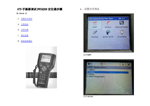
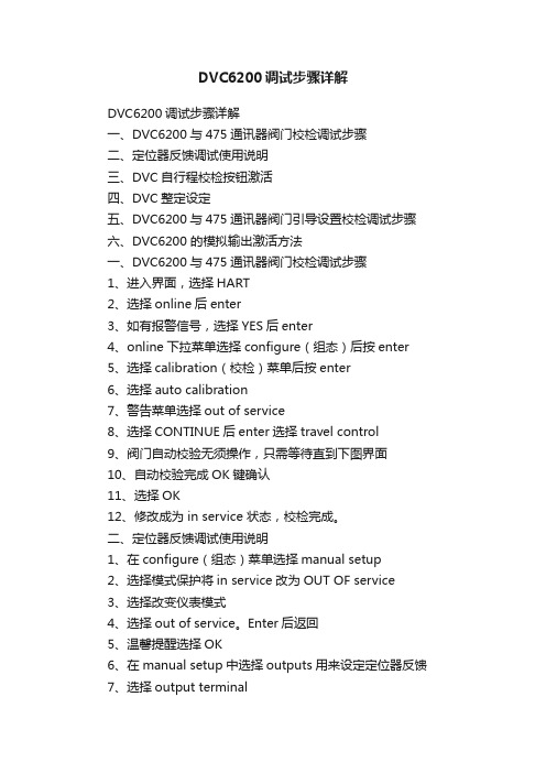
475手操器调试DVC6200定位器步骤By Derek LV1、 设置向导调试2、 行程校验3、 反馈设置4、 整定参数5、 校验按钮激活1、 设置向导调试选择HART选择online如有画面所示报警,选yes 选configure 选Guided Stup 选Device Setup仪表模式,改为out of service 压力单位,任选,一般用psi 放大器类型,一般选A or C选 Travel Control执行机构厂家,一般选FISHER。
执行机构型号,按铭牌所示来选。
其它厂家按类似来选。
执行机构规格,按铭牌选。
其它厂家按类似来选。
阀门故障开/故障关,按实际来选。
阀门开始动作,检测传感器方向。
选yes。
自动检测传感器方向,等待画面提示。
气路上有无放大器或快排阀,据实际情况选yes或no 发送设置数据,选send并enter确认。
当前设置数据发送至定位器,请等待。
其它数据用出厂默认值?一般选yes 出厂默认值发送到定位器,请等待。
设备设置完成。
要完成阀门调试,下一步要运行自动行程校验。
要运行自动行程校验吗?选yes并ENTER确认。
自动行程校验中,先后寻找Hi,Lo机械限位点。
调整输出偏差,此时阀门自动到中间位。
压力校验模式中,请等待。
自动行程校验完成。
如要是需要优化相应,请选择Performance Tuner,选OK. 定位器模式改为in service,即运行模式。
2、仅行程校验。
选HART选Online. 选yes 选configure选Calibration选Auto Calibration 更改模式,选out of service,并ENTER 选continue,并ENTER。
校验中,自动找开关两个限位点。
调整输出偏差,此时阀门自动移动到中间位。
校验完成。
仪表模式改回in service,即运行模式。
3、模拟量反馈的设置。
在configure菜单下选Manual setup 选择mode and protection。
费希尔DVC6200操作指导

DVC6200(带4-20ma 反馈反馈,,直行程直行程))操作指导一、 反馈件安装如下图所示,确认无论阀门在全开或全关状态下,校准板上的标准线(黑色塑料板上白线,指示的是定位器阀位传感器位置)在反馈磁条上标注的有效行程范围内(两条白色线之间)。
二、 自动行程校验步骤如下步骤如下::定位器将自动开始行程校验校验完成后必须将定位器投入校验完成后必须将定位器投入““In Service”模式模式。
三、 反馈信号设置1\ 功能激活注意:选择”SEND” 发送后才能完成阀位反馈功能激活。
2\反馈信号正反作用设置:在下面这个菜单的第3项Transmitter of Output 里,可以选择阀门在关闭状态或全开状态下反馈信号为4m A.四、调试按钮:在manual setup 菜单下功能激活:1\功能激活选择send 发送完成接线盒自行程校检按钮设置。
2\按压调试按钮3-10秒钟秒钟,,阀门将自动进行行程校验阀门将自动进行行程校验。
五、 灵敏度灵敏度的的调整如发现阀门有震荡,或阀门动作过慢。
可通过Tuning Set(简单理解为灵敏度)的调整进行改善。
点击send 发送。
有 C D E F G H I J K L M 可选,C 阀门反应最慢,M 阀门反应最快,反应越快越容易引起震荡。
六、 Instrument Mode 的设置设置::在进行定位器校验在进行定位器校验、、参数调整时参数调整时,,一般需要将Instrument Mode 置于Out Of Service (或者Not In Service )状态状态,,校验校验、、调整完成后必须投入In Service!。
DVC6200调试步骤详解
DVC6200调试步骤详解DVC6200调试步骤详解一、DVC6200与475通讯器阀门校检调试步骤二、定位器反馈调试使用说明三、DVC自行程校检按钮激活四、DVC整定设定五、DVC6200与475通讯器阀门引导设置校检调试步骤六、DVC6200 的模拟输出激活方法一、DVC6200与475通讯器阀门校检调试步骤1、进入界面,选择HART2、选择online后enter3、如有报警信号,选择YES后enter4、online下拉菜单选择configure(组态)后按enter5、选择calibration(校检)菜单后按enter6、选择auto calibration7、警告菜单选择out of service8、选择CONTINUE后enter选择travel control9、阀门自动校验无须操作,只需等待直到下图界面10、自动校验完成OK键确认11、选择OK12、修改成为 in service 状态,校检完成。
二、定位器反馈调试使用说明1、在configure(组态)菜单选择manual setup2、选择模式保护将in service改为OUT OF service3、选择改变仪表模式4、选择out of service。
Enter后返回5、温馨提醒选择OK6、在manual setup中选择outputs用来设定定位器反馈7、选择output terminal8、选择output terminal6、选择enable后enter7、一定要选择send发送后完成反馈使用设置。
记得将阀门改回in service状态。
三、DVC自行程校检按钮激活激活前必须将阀门设置成out of service状态,参考定位器反馈调试说明设置成为out of service。
1、在manual setup菜单下选择instrument2、选择terminal box3、选择calibration button按右键4、选择autocal后enter5、选择send发送完成接线盒自行程校检按钮设置。
- 1、下载文档前请自行甄别文档内容的完整性,平台不提供额外的编辑、内容补充、找答案等附加服务。
- 2、"仅部分预览"的文档,不可在线预览部分如存在完整性等问题,可反馈申请退款(可完整预览的文档不适用该条件!)。
- 3、如文档侵犯您的权益,请联系客服反馈,我们会尽快为您处理(人工客服工作时间:9:00-18:30)。
DVC6200安装与调试DVC6200数字式阀门控制器的结构特点[File Name or Event]DVC6200DVC6200 无连接非接触式智能阀门控制器z无机械式连接、非接触式反馈结构–定位器和阀杆的连接没有机械连接件定位和阀杆的连接有机械连接件z磁条滑道内装有霍尔效应传感器z磁性阵列的磁条与执行机构的阀杆或阀轴相连接磁条滑道z霍尔传感器将磁场和电流的变化关系转化为电信号。
与阀杆连接的磁条[File Name or Event]机械式连接的缺陷z连接件容易磨损:–机械磨损–高频振动z需要阀杆的实际行程来做诊断z库存量大z设置比较复杂DVC6200DVC6200可以解决机械连接存在的问题z 防暴外壳、专利的无连接结构、非接触行程反馈技术z 反馈技术在DVC2000上的成功使用得以保证(DVC2000自从2004年上市以来共销售50000台)z 可以做到0-24Inch (0-61cm )的行程z适用于所有执行机构的安装z可集成安装于Fisher 的GX 执行机构Curved Array1”Array Rotary Magnet Curved Array on1052 Actuator Integrated toGX Actuator Long Travel[File Name or Event]1 Array安装于多种执行机构上DVC6010DVC6020DVC6030DVC6035[File Name or Event]DVC6200的安装安装件符合国际标准,应用更加广泛:●集成安装到Fisher GX 控制阀和执行机构●集成安装到Fisher 旋转式执行机构;●远程安装;●直行程阀门;●角行程旋转式阀门;●IEC 60534−6−1 &VDI/VDE −3845;●IEC 60534−6−2 &VDI/VDE −3845;●NAMUR 安装标准的执行机构。
[File Name or Event]DVC6200直行程安装方式PluggedAir to OpenAir to CloseDVC6200旋转执行机构安装方式DVC6200角行程安装方式[File Name or Event]DVC6200长行程安装方式[File Name or Event]DVC6200 的优点DVC6200强大的反馈—增强仪表的可靠性–无需反馈臂、调整臂臂和连接件–抗磨损–无限的反馈循环寿命z模块化结构–维护容易–零部件可互换–减少备件库存z改善性能–小于0.5% 滞后–0.3% 线性度03%–1/2 % 阶跃响应[File Name or Event]Travel SensorProvides Feedback Key to Performance 操作原理Printed Wiring Board (PWB)PressureMinor Loopy fSensors Output A DriveSignalMinor Loop FeedbackT e r m i n a l B o x PneumaticRelayI/PConverter GaugeAir SupplyGauge Output BI/P OutputPressureControl & Communication SignalGauge [File Name or Event]DVC6200的调试1、将DVC6200的仪表模式设为非投用状态(Out ofService):S i)On Line(在线)→Setup & Diag(设置诊断)→Detailed Setup(详细设置)→Mode(模式)→Instrumrnt Mode(仪表模式)→Out of Service (非投用状态)仪表模式分为投用(In Service)和非投用状态(当需更改定位器参数或对定位Out of Service),当需更改定位器参数或对定位器进行重新校验时,可按此步骤操作。
操作完成后需将阀门定位器的仪表模式改为投用状态。
后需将阀门定位器的仪表模式改为投用状态[File Name or Event]DVC6200的调试2、阀门定位器校验时的参数设置:On Line(在线)→Setup & Diag(设置诊断)→Basic Setup(基本设置)→Auto Setup(自动设置)→Setup Wizard(设置诀窍)Setup Wizard→Travel Control(行程控制)→Pressure Unit:psi(压力单位:磅每平方英寸)→Max Supply Pressure(最大气源压力:弹簧膜片执行机构一般为35-40psi;双气缸执行机构一般片执行机构般为3540i双气缸执行机构般为80psi)[File Name or Event]DVC6200的调试→Actuator Manufacturer(执行机构制造商:可根据铭牌信息进行选择相应型号,若为其他厂家执据铭牌信息进行选择相应型号若为其他厂家执行机构可选Other或类似于Fisher的执行机构)Actuator Size(执行机构尺寸可根据铭牌信息→Actuator Size(执行机构尺寸:可根据铭牌信息进行选择尺寸,或类似于Fisher的执行机构尺寸)→Actuator Style(执行机构形式):A t t St l(执行机构形式)①Spring & Diaphragm(弹簧膜片执行机构)②Piston Dbl W/O Spring(双气缸不带弹簧)③Piston Sgl With Spring(单气缸带弹簧)Piston Sgl With Spring④Piston Dbl W/O Spring (双气缸带弹簧)[File Name or Event]DVC6200的调试→At minimal Instrument singal valve(最小信号4mA时阀门的状态)4A①Valve Closed 阀关②Valve Open 阀开→Feedback Connection 反馈连接的形式Feedback Connection①Rotary-All 旋转式(90度转角和长行程滚轮)②SStem-Standard标准直行程阀杆连接→Is it move the valve now to set the travel sensor s o e e a e o o se e a e se so motion?是否可让阀门动作以确定行程传方向?[File Name or Event]DVC6200的调试→Yes(选Yes,定位器会自动输出使阀门动作一个完整行程,从而确定行程传感器的旋转方向;个完整行程从而确定行程传感器的旋转方向若选No,需要人为确定行程传感器的方向顺时针Clockwise还是Counterclockwise,前提是能够确前提是能够确定磁条的旋转方向。
一般选Yes,让定位器自己判断)→Is a Volume Booster or Quick Release Valve present?(阀门是否安装有加速器或快速泄放阀,若装有加速器选YES后,375会提示要对加速器进行调整,没有装选NO直接进入下步)直接进入下一步)[File Name or Event]DVC6200的调试→Setup Wizard is ready to config to the DVC6200→Send (375会将设置好的参数发送给定位器)→Use factory defaults?(是否试用工厂缺省值)Use factory defaults→Yes:YES is recommended for initial setup(选Yes为推荐的有限设置)→To finish setting up the valve,run Auto Travel (完成阀门参数的设置可以进行自动校验Calib(完成阀门参数的设置,可以进行自动校验)→OK (选OK阀门会进行自动校验)OK[File Name or Event]DVC6200的调试→Warning:Calibration will cause suddenchenges in instrumrnt output,Continue?(校验h i i t t t t C ti将会引起仪表输出的突然改变,是否继续?)选确定自校验→YES(选Yes确定进行自动校验)→It is recommended to run relay adjustment fory jdouble acting relays in new installation?(在新安装的双作用阀门定位器推荐对气动放大器进行校验?)校验)→Yes or No?(选Yes需按375提示将气动放大器调到50%-70%范围内,确定双作用定位器的启动放大器正常时选NO直接进入校验)[File Name or Event]DVC6200的调试→Auto Calibration Progress?①Seeking Hi Drive Stop (搜寻高点对应20mA)②Seeking Lo Drive Stop (搜寻低点对应4mA )Seeking Lo Drive Stop4mA③Adjust Bias Output(搜寻中间位置)→Auto Calibration Completed3、按第1步将定位器的仪表模式设为投用状态InService。
[File Name or Event]DVC6200的调试1、当阀门定位器安装于阀门没有拆卸,感觉阀门位置有偏差时,可按以下步骤直接进行校验,而位置有偏差时可按以下步骤直接进行校验而不用做参数设置:On Line(在线)→Setup &Diag(设置诊断)→Basic Setup(基本设置)Basic Setup→Auto Setup(自动设置)→Auto Calib Travel2、当阀门位置发生超调或响应迟缓时,可按以下当阀门位置发生超调或响应迟缓时可按以下方法调试:On Line(在线)→Setup & Diag(设置诊断)→Basic Setup(基本设置)→ManualBasic Setup Manual Setup(手动设置)→Tuning & Calib → Tuning (根据需要由C M修改合适的响应值)C-M[File Name or Event]。