M66222SP中文资料
MHW6222中文资料

REV 6
RF DEVICE DATA ©MOTOROLA Motorola, Inc. 1994
MHW6222 1
元器件交易网
PACKAGE DIMENSIONS
–A– S –Z– –F– J V
Q
2 PL
0.25 (0.010)
M
T F
M
A
M
NOTES: 1. DIMENSIONING AND TOLERANCING PER ANSI Y14.5M, 1982. 2. CONTROLLING DIMENSION: INCH. DIM A B C D E F G J K L N P Q R S U V W INCHES MIN MAX ––– 1.775 ––– 1.085 ––– 0.840 0.018 0.022 0.465 0.510 0.300 0.325 0.100 BSC 0.156 BSC 0.315 0.355 1.00 BSC 0.165 BSC 0.100 BSC 0.148 0.168 ––– 0.595 1.500 BSC 0.200 BSC 0.280 BSC 0.435 0.450 MILLIMETERS MIN MAX ––– 45.08 ––– 27.56 ––– 21.34 0.46 0.56 11.81 12.95 7.62 8.25 2.54 BSC 3.96 BSC 8.00 8.50 25.40 BSC 4.10 BSC 2.54 BSC 3.76 4.27 ––– 15.11 38.10 BSC 5.08 BSC 7.11 BSC 11.05 11.43
CASE 714–06 ISSUE K
Motorola reserves the right to make changes without further notice to any products herein. Motorola makes no warranty, representation or guarantee regarding the suitability of its products for any particular purpose, nor does Motorola assume any liability arising out of the application or use of any product or circuit, and specifically disclaims any and all liability, including without limitation consequential or incidental damages. “Typical” parameters can and do vary in different applications. All operating parameters, including “Typicals” must be validated for each customer application by customer’s technical experts. Motorola does not convey any license under its patent rights nor the rights of others. Motorola products are not designed, intended, or authorized for use as components in systems intended for surgical implant into the body, or other applications intended to support or sustain life, or for any other application in which the failure of the Motorola product could create a situation where personal injury or death may occur. Should Buyer purchase or use Motorola products for any such unintended or unauthorized application, Buyer shall indemnify and hold Motorola and its officers, employees, subsidiaries, affiliates, and distributors harmless against all claims, costs, damages, and expenses, and reasonable attorney fees arising out of, directly or indirectly, any claim of personal injury or death associated with such unintended or unauthorized use, even if such claim alleges that Motorola was negligent regarding the design or manufacture of the part. Motorola and are registered trademarks of Motorola, Inc. Motorola, Inc. is an Equal Opportunity/Affirmative Action Employer.
LT6220资料
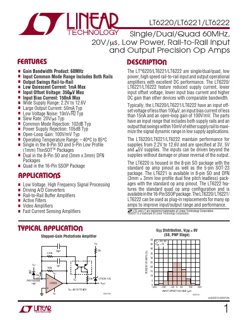
12ELECTRICAL CHARACTERISTICST A = 25°C, V S = 5V, 0V; V S = 3V, 0V; V CM = V OUT = half supply, unless otherwise notedSYMBOL PARAMETER CONDITIONS MIN TYP MAX UNITS V OS Input Offset Voltage V CM = 0V70350µVV CM = 0V (DD Package)150700µVV CM = 0V (S5 Package)200850µVV CM = V S0.5 2.5mVV CM = V S (S5 Package)0.53mV ∆V OS Input Offset Voltage Shift V S = 5V, V CM = 0V to 3.5V30195µVV S = 3V, V CM = 0V to 1.5V15120µV Input Offset Voltage Match (Channel-to-Channel)V CM = 0V100600µV (Note 9)V CM = 0V (DD Package)1501100µV I B Input Bias Current V CM = 1V15150nAV CM = V S250600nA Input Bias Current Match (Channel-to-Channel)V CM = 1V15175nA (Note 9)V CM = V S20250nA I OS Input Offset Current V CM = 1V15100nAV CM = V S15100nA Input Noise Voltage0.1Hz to 10Hz0.5µV P-P e n Input Noise Voltage Density f = 10kHz10nV/√Hz i n Input Noise Current Density f = 10kHz0.8pA/√Hz C IN Input Capacitance2pF A VOL Large Signal Voltage Gain V S = 5V, V O = 0.5V to 4.5V, R L = 1k at V S/235100V/mVV S = 5V, V O = 1V to 4V, R L = 100Ω at V S/2 3.510V/mVV S = 3V, V O = 0.5V to 2.5V, R L = 1k at V S/23090V/mV CMRR Common Mode Rejection Ratio V S = 5V, V CM = 0V to 3.5V85102dBV S = 3V, V CM = 0V to 1.5V82102dB CMRR Match (Channel-to-Channel) (Note 9)V S = 5V, V CM = 0V to 3.5V79100dBV S = 3V, V CM = 0V to 1.5V76100dB Input Common Mode Range0V S V PSRR Power Supply Rejection Ratio V S = 2.5V to 10V, V CM = 0V84105dB PSRR Match (Channel-to-Channel) (Note 9)79105dB Minimum Supply Voltage (Note 6) 2.2 2.5V V OL Output Voltage Swing LOW (Note 7)No Load540mVI SINK = 5mA100200mVI SINK = 20mA325650mV V OH Output Voltage Swing HIGH (Note 7)No Load540mVI SOURCE = 5mA130250mVI SOURCE = 20mA475900mV I SC Short-Circuit Current V S = 5V2045mAV S = 3V2035mA I S Supply Current Per Amplifier0.91mA GBW Gain-Bandwidth Product V S = 5V, Frequency = 1MHz3560MHz SR Slew Rate V S = 5V, A V = –1, R L= 1k, V O = 4V1020V/µs FPBW Full Power Bandwidth V S = 5V, A V = 1, V O = 4V p-p 1.6MHz HD Harmonic Distortion V S = 5V, A V = 1, R L= 1k, V O = 2V P-P, f C = 500kHz–77.5dBc t S Settling Time0.01%, V S = 5V, V STEP = 2V, A V = 1, R L= 1k 300ns ∆G Differential Gain (NTSC)V S = 5V, A V = 2, R L= 1k0.3%∆θDifferential Phase (NTSC)V S = 5V, A V = 2, R L= 1k0.3Degsn622012 622012fs34sn622012 622012fsSYMBOL PARAMETER CONDITIONS MIN TYP MAX UNITS V OSInput Offset VoltageV CM = 0V●90500µV V CM = 0V (DD Package)●180850µV V CM = 0V (S5 Package)●2301250µV V CM = V S●0.53mV V CM = V S (S5 Package)●0.5 3.5mV ∆V OSInput Offset Voltage ShiftV S = 5V, V CM = 0V to 3.5V ●30280µV V S = 3V, V CM = 0V to 1.5V●15190µV Input Offset Voltage Match (Channel-to-Channel)V CM = 0V ●110850µV (Note 9)V CM = 0V (DD Package)●1801400µV V OS TC Input Offset Voltage Drift (Note 8)● 1.55µV/°C (S5 Package)● 3.510µV/°C I BInput Bias CurrentV CM = 1V●20175nA V CM = V S – 0.2V ●275800nA Input Bias Current Match (Channel-to-Channel)V CM = 1V●15200nA (Note 9)V CM = V S – 0.2V ●20300nA I OS Input Offset Current V CM = 1V●15125nA V CM = V S – 0.2V●15125nA A VOLLarge Signal Voltage GainV S = 5V, V O = 0.5V to 4.5V, R L = 1k at V S /2●3090V/mV V S = 5V, V O = 1V to 4V, R L = 100Ω at V S /2●39V/mV V S = 3V, V O = 0.5V to 2.5V, R L = 1k at V S /2●2580V/mV CMRR Common Mode Rejection RatioV S = 5V, V CM = 0V to 3.5V ●82100dB V S = 3V, V CM = 0V to 1.5V ●78100dB CMRR Match (Channel-to-Channel) (Note 9)V S = 5V, V CM = 0V to 3.5V ●77100dB V S = 3V, V CM = 0V to 1.5V ●73100dBInput Common Mode Range●0V SV PSRR Power Supply Rejection RatioV S = 2.5V to 10V, V CM = 0V●81104dB PSRR Match (Channel-to-Channel) (Note 9)●76104dB Minimum Supply Voltage (Note 6)●2.2 2.5V V OLOutput Voltage Swing LOW (Note 7)No Load ●850mV I SINK = 5mA ●110220mV I SINK = 20mA ●375750mV V OHOutput Voltage Swing HIGH (Note 7)No Load●850mV I SOURCE = 5mA ●150300mV I SOURCE = 20mA ●6001100mV I SC Short-Circuit Current V S = 5V ●2040mA V S = 3V●2030mAI S Supply Current Per Amplifier ●1 1.4mA GBW Gain-Bandwidth Product V S = 5V, Frequency = 1MHz ●3060MHz SRSlew RateV S = 5V, A V = –1, R L = 1k, V O = 4V P-P●918V/µsELECTRICAL CHARACTERISTICSThe ● denotes the specifications which apply over the 0°C ≤ T A ≤ 70°Ctemperature range. V S = 5V, 0V; V S = 3V, 0V; V CM = V OUT = half supply, unless otherwise noted.5sn622012 622012fsSYMBOL PARAMETER CONDITIONS MIN TYP MAX UNITS V OSInput Offset VoltageV CM = 0V●125700µV V CM = 0V (DD Package)●3001300µV V CM = 0V (S5 Package)●3502000µV V CM = V S●0.75 3.5mV V CM = V S (S5 Package)●1 4.5mV ∆V OSInput Offset Voltage ShiftV S = 5V, V CM = 0V to 3.5V ●30300µV V S = 3V, V CM = 0V to 1.5V●30210µV Input Offset Voltage Match (Channel-to-Channel)V CM = 0V ●1751200µV (Note 9)V CM = 0V (DD Package)●3002200µV V OS TC Input Offset Voltage Drift (Note 8)● 1.57.5µV/°C (S5 Package)● 3.515µV/°C I BInput Bias CurrentV CM = 1V●25200nA V CM = V S – 0.2V ●300900nA Input Bias Current Match (Channel-to-Channel)V CM = 1V●15250nA (Note 9)V CM = V S – 0.2V ●20350nA I OS Input Offset Current V CM = 1V●20150nA V CM = V S – 0.2V●20150nA A VOLLarge Signal Voltage GainV S = 5V, V O = 0.5V to 4.5V, R L = 1k at V S /2●2570V/mV V S = 5V, V O = 1.5V to 3.5V, R L = 100Ω at V S /2● 2.58V/mV V S = 3V, V O = 0.5V to 2.5V, R L = 1k at V S /2●2060V/mV CMRR Common Mode Rejection RatioV S = 5V, V CM = 0V to 3.5V ●81100dB V S = 3V, V CM = 0V to 1.5V ●77100dB CMRR Match (Channel-to-Channel) (Note 9)V S = 5V, V CM = 0V to 3.5V ●76100dB V S = 3V, V CM = 0V to 1.5V ●72100dBInput Common Mode Range●0V SV PSRR Power Supply Rejection RatioV S = 2.5V to 10V, V CM = 0V●79104dB PSRR Match (Channel-to-Channel) (Note 9)●74104dB Minimum Supply Voltage (Note 6)●2.2 2.5V V OLOutput Voltage Swing LOW (Note 7)No Load ●1060mV I SINK = 5mA ●120240mV I SINK = 10mA ●220450mV V OHOutput Voltage Swing HIGH (Note 7)No Load●1060mV I SOURCE = 5mA ●160325mV I SOURCE = 10mA ●325650mV I SC Short-Circuit Current V S = 5V ●12.530mA V S = 3V●12.525mAI S Supply Current Per Amplifier ● 1.1 1.5mA GBW Gain-Bandwidth Product V S = 5V, Frequency = 1MHz ●2550MHz SRSlew RateV S = 5V, A V = –1, R L = 1k, V O = 4V●815V/µsELECTRICAL CHARACTERISTICSThe ● denotes the specifications which apply over the –40°C ≤ T A ≤ 85°Ctemperature range. V S = 5V, 0V; V S = 3V, 0V; V CM = V OUT = half supply unless otherwise noted. (Note 5)ELECTRICAL CHARACTERISTICST A = 25°C, V S = ±5V, V CM = 0V, V OUT = 0V, unless otherwise noted.SYMBOL PARAMETER CONDITIONS MIN TYP MAX UNITS V OS Input Offset Voltage V CM = –5V80500µVV CM = –5V (DD Package)150750µVV CM = –5V (S5 Package)200900µVV CM = 5V0.7 2.5mVV CM = 5V (S5 Package)0.73mV ∆V OS Input Offset Voltage Shift V CM = –5V to 3.5V70675µV Input Offset Voltage Match (Channel-to-Channel)V CM = –5V100850µVV CM = –5V (DD Package)1501300µV I B Input Bias Current V CM = –4V20150nAV CM = 5V250700nA Input Bias Current Match (Channel-to-Channel)V CM = –4V15175nAV CM = 5V20250nA I OS Input Offset Current V CM = –4V15100nAV CM = 5V15100nA Input Noise Voltage0.1Hz to 10Hz0.5µV P-P e n Input Noise Voltage Density f = 10kHz10nV/√Hz i n Input Noise Current Density f = 10kHz0.8pA/√Hz C IN Input Capacitance f = 100kHz2pF A VOL Large Signal Voltage Gain V O = –4V to 4V, R L = 1k3595V/mVV O = –2V to 2V, R L = 100Ω 3.510V/mV CMRR Common Mode Rejection Ratio V CM = –5V to 3.5V82102dB CMRR Match (Channel-to-Channel)77100dB Input Common Mode Range V S–V S+V PSRR Power Supply Rejection Ratio V S+ = 2.5V to 10V, V S–= 0V, V CM = 0V84105dB PSRR Match (Channel-to-Channel)79105dB V OL Output Voltage Swing LOW (Note 7)No Load540mVI SINK = 5mA100200mVI SINK = 20mA325650mV V OH Output Voltage Swing HIGH (Note 7)No Load540mVI SOURCE = 5mA130250mVI SOURCE = 20mA475900mV I SC Short-Circuit Current2550mA I S Supply Current Per Amplifier1 1.5mA GBW Gain-Bandwidth Product Frequency = 1MHz60MHz SR Slew Rate A V = –1, R L = 1k, V O = ±4V,20V/µsMeasure at V O = ±2VFPBW Full Power Bandwidth V O = 8V P-P0.8MHz HD Harmonic Distortion A V = 1, R L= 1k, V O = 2V p-p, f c = 500kHz–77.5dBc t S Settling Time0.01%, V STEP = 5V, A V = 1, R L = 1k375ns ∆G Differential Gain (NTSC)A V = 2, R L = 1k0.15%∆θDifferential Phase (NTSC)A V = 2, R L = 1k0.6Deg6sn622012 622012fs7sn622012 622012fsSYMBOL PARAMETER CONDITIONSMIN TYP MAX UNITS V OSInput Offset VoltageV CM = –5V●100650µV V CM = –5V (DD Package)●180900µV V CM = –5V (S5 Package)●2301300µV V CM = 5V●0.753mV V CM = 5V (S5 Package)●0.75 3.5mV ∆V OSInput Offset Voltage ShiftV CM = –5V to 3.5V●90850µV Input Offset Voltage Match (Channel-to-Channel)V CM = –5V ●901100µV (Note 9)V CM = –5V (DD Package)●1801500µV V OS TC Input Offset Voltage Drift (Note 8)● 1.55µV/°C (S5 Package)● 3.510µV/°C I BInput Bias CurrentV CM = –4V ●20175nA V CM = 4.8V ●275800nA Input Bias Current Match (Channel-to-Channel)V CM = –4V ●15200nA (Note 9)V CM = 4.8V ●20300nA I OS Input Offset Current V CM = –4V ●15125nA V CM = 4.8V●15125nA A VOL Large Signal Voltage Gain V O = –4V to 4V, R L = 1k ●3090V/mV V O = –2V to 2V, R L =100Ω●39V/mV CMRRCommon Mode Rejection RatioV CM = –5V to 3.5V●80100dB CMRR Match (Channel-to-Channel) (Note 9)●75100dBInput Common Mode Range●V S –V S +V PSRR Power Supply Rejection RatioV S + = 2.5V to 10V, V S –= 0V, V CM = 0V●81104dB PSRR Match (Channel-to-Channel) (Note 9)●76104dB V OLOutput Voltage Swing LOW (Note 7)No Load ●850mV I SINK = 5mA ●110220mV I SINK = 20mA ●375750mV V OHOutput Voltage Swing HIGH (Note 7)No Load●850mV I SOURCE = 5mA ●150300mV I SOURCE = 20mA ●6001100mV I SC Short-Circuit Current ●2040mA I S Supply Current Per Amplifier ●1.22mA GBW Gain-Bandwidth Product Frequency = 1MHz ●60MHz SRSlew RateA V = –1, R L = 1k , V O = ±4V,●18V/µsMeasure at V O = ±2VELECTRICAL CHARACTERISTICSThe ● denotes the specifications which apply over the 0°C ≤ T A ≤ 70°Ctemperature range. V S = ±5V, V CM = 0V, V OUT = 0V, unless otherwise noted.SYMBOL PARAMETER CONDITIONS MIN TYP MAX UNITS V OS Input Offset Voltage V CM = –5V●150800µVV CM = –5V (DD Package)●3001300µVV CM = –5V (S5 Package)●3502000µVV CM = 5V●0.75 3.5mVV CM = 5V (S5 Package)●1 4.5mV ∆V OS Input Offset Voltage Shift V CM = – 5V to 3.5V●90950µV Input Offset Voltage Match (Channel-to-Channel)V CM = –5V●1751350µV (Note 9)V CM = –5V (DD Package)●3002200µV V OS TC Input Offset Voltage Drift (Note 8)● 1.57.5µV/°C(S5 Package)● 3.515µV/°C I B Input Bias Current V CM = –4V●25200nAV CM = 4.8V●300900nA Input Bias Current Match (Channel-to-Channel)V CM = –4V●15250nA (Note 9)V CM = 4.8V●20350nA I OS Input Offset Current V CM = –4V●20150nAV CM = 4.8V●20150nA A VOL Large Signal Voltage Gain V O = –4V to 4V, R L = 1k●2570V/mVV O = –1V to 1V, R L = 100Ω● 2.58V/mV CMRR Common Mode Rejection Ratio V CM = –5V to 3.5V●79100dB CMRR Match (Channel-to-Channel) (Note 9)●74100dB Input Common Mode Range●–5 5V PSRR Power Supply Rejection Ratio V S+= 2.5V to 10V, V S– = 0V, V CM = 0V●79104dB PSRR Match (Channel-to-Channel) (Note 9)●74104dB V OL Output Voltage Swing LOW (Note 7)No Load●1060mVI SINK = 5mA●120240mVI SINK = 10mA●220450mV V OH Output Voltage Swing HIGH (Note 7)No Load●1060mVI SOURCE = 5mA●160325mVI SOURCE = 10mA●325650mV I SC Short-Circuit Current●12.530mA I S Supply Current● 1.4 2.25mA GBW Gain-Bandwidth Product Frequency = 1MHz●50MHz SR Slew Rate A V = –1, R L = 1k,V O = ±4V,●15V/µsMeasure at V O = ±2VNote 1: Absolute Maximum Ratings are those values beyond which the life of a device may be impaired.Note 2: The inputs are protected by back-to-back diodes. If the differential input voltage exceeds 1.4V, the input current should be limited to less than 10mA.Note 3: A heat sink may be required to keep the junction temperature below the absolute maximum rating when the output is shorted indefinitely.Note 4: The LT6220C/LT6221C/LT6222C and LT6220I/LT6221I/LT6222I are guaranteed functional over the temperature range of –40°C and 85°C. Note 5: The LT6220C/LT6221C/LT6222C are guaranteed to meet specified performance from 0°C to 70°C. The LT6220C/LT6221C/LT6222C are designed, characterized and expected to meet specified performance from –40°C to 85°C but is not tested or QA sampled at these temperatures. The LT6220I/LT6221I/LT6222I are guaranteed to meet specified performance from –40°C to 85°C.Note 6: Minimum supply voltage is guaranteed by power supply rejection ratio test.Note 7: Output voltage swings are measured between the output and power supply rails.Note 8: This parameter is not 100% tested.Note 9: Matching parameters are the difference between amplifiers A and D and between B and C on the LT6222; between the two amplifiers on the LT6221.Note 10: Thermal resistance (θJA) varies with the amount of PC board metal connected to the package. The specified values are for short traces connected to the leads. If desired, the thermal resistance can be substantially reduced by connecting Pin 2 of the LT6220CS5/LT6220IS5 or the underside metal of DD packages to a larger metal area (V S– trace).ELECTRICAL CHARACTERISTICS The ● denotes the specifications which apply over the –40°C ≤ TA≤ 85°C temperature range. V S = ±5V, V CM = 0V, V OUT = 0V, unless otherwise noted. (Note 5)8sn622012 622012fs91011TIME (SECONDS)8622012 G202461071359V S = 5V, 0VV S = ±5V PHASEGain and Phase vs FrequencyV S = 5V, 0V100ns/DIV622012 G36A V = 1R L = 1k121314sn622012 622012fsA pair of complementary common emitter stages Q14/Q15that enable the output to swing from rail-to-rail construct the output stage. The capacitors C2 and C3 form the local feedback loops that lower the output impedance at high frequency. These devices are fabricated by Linear Technology’s proprietary high speed complementary bi-polar process.Power DissipationThe LT6222, with four amplifiers, is housed in a small 16-lead SSOP package and typically has a thermal resis-tance (θJA ) of 135°C/W. It is necessary to ensure that the die’s junction temperature does not exceed 150°C. The junction temperature, T J , is calculated from the ambient temperature, T A , power dissipation, P D , and thermal resis-tance, θJA :T J = T A + (P D • θJA )The power dissipation in the IC is the function of the supply voltage, output voltage and the load resistance. For a given supply voltage, the worst-case power dissipation P D(MAX)occurs when the maximum supply current and the output voltage is at half of either supply voltage for a given load resistance. P D(MAX) is given by:P V I V R D MAX S S MAX S L ()()•/=()+⎛⎝⎜⎞⎠⎟22Example: F or an LT6222 in a 16-lead SSOP package operating on ±5V supplies and driving a 100Ω load, the worst-case power dissipation is given by:P Amp mA mWD MAX ()/•../...=()+()=+=1018251000018006258052If all four amplifiers are loaded simultaneously, then the total power dissipation is 322mW.The maximum ambient temperature at which the part is allowed to operate is:T A = T J – (P D(MAX) • 135°C/W)= 150°C – (0.322W • 135°C/W) = 106.5°CAPPLICATIO S I FOR ATIOW UUU Input Offset VoltageThe offset voltage will change depending upon which input stage is active. The PNP input stage is active from the negative supply rail to 1.2V below the positive supply rail,then the NPN input stage is activated for the remaining input range up to the positive supply rail during which the PNP stage remains inactive. The offset voltage is typically less than 70µV in the range that the PNP input stage is active.Input Bias CurrentThe LT6220/LT6221/LT6222 employ a patent pending technique to trim the input bias current to less than 150nA for the input common mode voltage of 0.2V above the negative supply rail to 1.2V below the positive rail. The low input offset voltage and low input bias current of the LT6220/LT6221/LT6222 provide precision performance especially for high source impedance applications.OutputThe LT6220/LT6221/LT6222 can deliver a large output current, so the short-circuit current limit is set around 50mA to prevent damage to the device. Attention must be paid to keep the junction temperature of the IC below the absolute maximum rating of 150°C (refer to the Power Dissipation section) when the output is in continuous short circuit. The output of the amplifier has reverse-biased diodes connected to each supply. If the output is forced beyond either supply, unlimited current will flow through these diodes. If the current is transient and limited to several hundred milliamperes, no damage will occur to the device.Overdrive ProtectionWhen the input voltage exceeds the power supplies, two pair of crossing diodes, D1 to D4, will prevent the output from reversing polarity. If the input voltage exceeds either power supply by 700mV, diode D1/D2 or D3/D4 will turn on to keep the output at the proper polarity. For the phase reversal protection to perform properly, the input current must be limited to less than 5mA. If the amplifier is155µs/DIV622012 F03Figure 3. Stepped-Gain Photodiode Amplifier Response Single 3V Supply, 1MHz, 4th Order Butterworth Filter161718Information furnished by Linear Technology Corporation is believed to be accurate and reliable. However, no responsibility is assumed for its use. Linear Technology Corporation makes no represen-tation that the interconnection of its circuits as described herein will not infringe on existing patent rights.1920Linear Technology Corporation1630 McCarthy Blvd., Milpitas, CA 95035-7417(408) 432-1900 ● F AX: (408) 434-0507 ● © LINEAR TECHNOLOGY CORPORA TION 2003LT/TP 0204 1K • PRINTED IN USA。
SP6222中文资料

DESCRIPTION■ SMPS Post-Regulator ■ DC-to-DC Modules ■ Medical Devices ■ Data Cable ■ PagersFEATURESAPPLICATIONSThe SP6222 and SP6223 are CMOS LDOs designed to meet a broad range of applications that require accuracy,speed and ease of use. These LDOs offer extremely low quiescent current which only increases slightly under load,thus providing advantages in ground current performance over bipolar LDOs. The LDOs handle an extremely wide load range and guarantee stability with a 1μF ceramic output capacitor. They have excellent low frequency PSRR,not found in other CMOS LDOs and thus offer exceptional Line Regulation. High frequency PSRR is 55dB (typical)at 1kHz. Load Regulation is excellent and temperature stability is comparable to bipolar LDOs. An enable feature is provided on all versions. The SP6222/6223 is available in fixed and adjustable output voltage versions in industry standard SC70 and SOT23 packages.TYPICAL APPLICATION CIRCUITVery low Dropout Voltage: 200mV typ (150mA load) High Output Setpoint Accuracy of 2% Very low Input Voltages Down to 1.6VPower-saving Shutdown Mode of 150nA (typ) Fast Turn-on (90μs) and Turn-off (90μs)Extremely low Quiescent Current of 14μA (typ) Very Tight Line regulation, 0.2%/V Load Regulation 0.125 mV/mA Thermal Shutdown ProtectionLow Noise Output, 100μV RMS With 10nF Bypass Fixed or Adjustable Output Versions AvailableAvailable in RoHS Compliant, Lead Free Packages:SC70 and SOT23■ Cellular Telephones■ Laptop, Notebooks and Palmtop Computers ■ Battery-Powered Equipment ■ Consumer/ Personal Electronics3.0VENABLEELECTRICAL CHARACTERISTICSABSOLUTE MAXIMUM RATINGSThese are stress ratings only and functional operation of the device at these ratings or any other above those indicated in the operation sections of the specifications below is not implied. Exposure to absolute maximum rating conditions for extended periods of time may affect reliability.Storage Temperature...........................-65°C to +150°C Junction Temperature (T J )....................-40°C to +125°C Lead Temperature (soldering 5s).........................300°C Supply Input Voltage (V IN ).............................-2V to 6V Output Voltage (V OUT ).........................-0.6V to V IN +1V Enable Input Voltage (V EN )............................-2V to 7V Power Dissipation (P D )..........Internally Limited, Note 1Unless otherwise specified: V IN = V OUT + 0.3V to 4.5V, C OUT = 1μF ceramic, C IN = 1μF ceramic, I OUT =100μA, T A = 25°C.Bold values apply over the full operating temperature range (-40°C to 125°C).Note 1.The maximum allowable power dissipation at any T A (ambient temperature) is P D (MAX) = (T J (MAX)– T A ) /θJA . Exceeding the maximum allowable power dissipation will result in excessive die temperature, and the regulator will go into thermal shutdown. The θJA of the SP6222/23 (SC-70-5) is 330°C/W mounted on a PC board with minimum copper area (see “Thermal Considerations” section for further details).Note 2.Minimum V IN must meet 2 conditions: V IN >1.6V and V IN > {V OUT + DOV}Note 3.Dropout Voltage DOV is defined as the input to output differential at which the output voltage drops2% below its nominal value measured at 1V differential. The DOV specification is not applicable to output voltages less than 2.7V.ELECTRICAL CHARACTERISTICSUnless otherwise specified: VIN = VOUT+ 0.3V to 4.5V, COUT= 1μF ceramic, CIN= 1μF ceramic, IOUT=100μA, TA= 25°C.Bold values apply over the full operating temperature range (-40°C to 125°C).General OverviewThe SP6222 and SP6223 are CMOS LDOs designed to meet a broad range of low voltage applications that require accuracy and ease of use. The SP6222 offers a 50mA output current while the SP6223 offers an output current of 150mA. The SP6222 is available in a 2.5V or 3.0V fixed output along with an adjustable output version. The SP6223 is offered in an adjustable output only. These LDOs have a minimum input voltage of only 1.6V and a maximum input voltage of 4.5V. The output voltage can be programmed to as low as 0.9V and have a maximum dropout voltage rating of 100mV for the SP6222 and 300mV for the SP6223. Both devices are equipped with an enable (EN) input for very low current (10nA typical) shutdown mode.Enable / Shutdown OperationThe SP6222/6223 is turned on by providing 1.6V or greater to the EN pin. To place the device into shutdown pull the EN pin below 0.4V. If this feature is not required connect EN to input supply to always enable the device whenever power is applied.Input / Output CapacitorThe SP6222/6223 is designed to operate using very small ceramic capacitors. The minimum input and output capacitor value for stable operation is 1.0μF. The output capacitor value may be increased without limit to improve transient response. Place these capacitors as close as possible to the device.Bypass (BYP) CapacitorThe fixed output versions offer a BYP pin to decouple the bandgap reference. Connecting an external 10nF capacitor from BYP to GND can reduce output noise. If output noise is not a concern the BYP pin may be left open. When a bypass capacitor is used the turn on time is slower. See the following turn on time plots for various BYP capacitor values. The adjustable output version does not offer this BYP input. Adjustable RegulatorThe output of the device can be programmed to a specific voltage by using two external resistors connected to the ADJ pin (see Typical Application Circuit for Adjustable output). The resistors set APPLICATION INFORMATIONthe output voltage based on the following equation:V OUT = V REF *(R1/R2 + 1)Resistor values are not critical because the ADJ (adjust) pin has a high impedance, but for best performance use resistor values of 470K Ω or less.Thermal ConsiderationsThe SP6222/6223 is designed to provide 50mA -150mA of continuous current in a tiny package. Maximum power dissipation can be calculated based on the output current and the voltage drop across the part. To determine the maximum power dissipation of the package, use the junction-to-ambient thermal resistance of the device and the following equation:P D(MAX) = (T J(max) – T A ) / θJAT J(max) is the maximum junction temperature of the die and is 125o C.T A is the ambient temperature. θJA is the junction-to-ambient thermal resistance of the package. The SOT-23 package has a θJA of approximately 191o C/W and the SC70 package has a θof approximately 330o C/W.The actual power dissipation of the regulator circuit can be determined by using the simplified equation:P D = (V IN – V OUT ) * I OUTTo prevent the device from entering thermal shutdown, maximum power dissipation cannot be exceeded.Layout ConsiderationsThe primary path of heat conduction out of the package is via the package leads. Therefore, careful consideration must be taken into account for optimizing layout.1.Attaching the part to a large copper footprint will enable better heat transfer from the device, especially where there are internal ground and power planes.2.Place the input and output capacitors close to the device for optimal transient response and device behavior.3.Connect all ground connections directly to the ground plane. In case there is no ground plane,connect to a common ground point before connecting to board ground.APPLICATION INFORMATIONAPPLICATION INFORMATIONVoutIout @ 100mA/divSP6223 1.2Vout fixed Cin = Cout = 1.0uF Cer Iout = 100uA to 150mASP6223 1.2Vout fixed Cin = Cout = 1.0uF Cer Iout = 100uA to 150mAVoutIout @ 100mA/divIout @ 100mA/divSP6223 1.2Vout fixed Cin = Cout = 1.0uF Cer Iout = 100uA to 100mAVoutSP6223 1.2Vout fixed Cin = Cout = 1.0uF Cer Iout = 100uA to 100mAVoutLoad Transient Response, 100μA to 150mA,Vin = 1.6VLoad Transient Response, 100Vin = 3.3VLoad Transient Response, 100Vin = 1.6VLoad Transient Response, 100Vin = 3.3VAPPLICATION INFORMATIONIout @ 100mA/divSP6223 1.2Vout fixed Cin = Cout = 1.0uF Cer Iout = 100uA to 50mAVoutVoutIout @ 100mA/divSP6223 1.2Vout fixed Cin = Cout = 1.0uF Cer Iout = 100uA to 50mASP6222 2.5V fixedVin = 3.0V, Iout = 10mA Cbyp = openEnableVoutSP6222 2.5V fixedVin = 3.0V, Iout = 50mA Cbyp = openEnableLoad Transient Response, 100Vin = 1.6VLoad Transient Response, 100Vin = 3.3VTurn on time, Vin = 3.0V, Iout = 10mA, CBYP = OpenTurn on time, Vin = 3.0V, Iout = 50mA, CBYP = OpenAPPLICATION INFORMATIONSP6222 2.5V fixedVin = 3.0V, Iout = 10mA Cbyp = 1nFVoutEnableSP6222 2.5V fixedVin = 3.0V, Iout = 50mA Cbyp = 1nF VoutEnableSP6222 2.5V fixedVin = 3.0V, Iout = 10mA Cbyp = 10nFVoutEnableSP6222 2.5V fixedVin = 3.0V, Iout = 50mA Cbyp = 10nFEnableTurn on time, Vin = 3.0V, Iout = 10mA,CBYP = 1nFTurn on time, Vin = 3.0V, Iout = 50mA,CBYP = 1nFTurn on time, Vin = 3.0V, Iout = 10mA,CBYP = 10nFTurn on time, Vin = 3.0V, Iout = 50mA,CBYP = 10nFAPPLICATION INFORMATIONSP6222 2.5V fixedVin = 3.0V, Iout = 10mA Cbyp = 100nFVoutEnableVoutSP6222 2.5V fixedVin = 3.0V, Iout = 50mA Cbyp = 100nFEnable6222 3.0V output noise010020030040050060070080090011010010001000010000Bypass Cap (pF)N o i s e (u V r m s )100uA 10mA 50mATurn on time, Vin = 3.0V, Iout =10mA, CBYP = 100nFTurn on time, Vin = 3.0V, Iout =50mA, CBYP = 100nFSP6222 3.0V Output Noise vs.CBYPAPPLICATION INFORMATION10100100010000100000100000010000000Frequency (Hz)SP6222 3.0Vout PSRR 10mA, 4.5Vin, Cbyp-10nFAPPLICATION INFORMATION639LQ9RXW7\SLFDO $SSOLFDWLRQ &LUFXLW IRU $GMXVWDEOH 2XWSXW9287 95() > 5 5 @10100100010000100000100000010000000PACKAGE: 5 PIN SC-70PACKAGE: 5 PIN SOT-23Sipex Corporation reserves the right to make changes to any products described herein. Sipex does not assume any liability arising out of the application or use of any product or circuit described herein; neither does it convey any license under its patent rights nor the rights of others.ORDERING INFORMATIONSipex Corporation Headquarters and Sales Office233 South Hillview Drive Milpitas, CA 95035TEL: (408) 934-7500FAX: (408) 935-7600Available in lead free packaging only./TR = Tape and ReelPack quantity is 3,000 for SC-70 and 2,500 for SOT-23.Part Number Temperature Range Voltage Option Package TypeSP6222EC5-2-5-L...................-40˚C to +125˚C ................2.5V .......... (Lead F ree) 5 Pin SC70SP6222EC5-2-5-L/TR...............-40˚C to +125˚C ................2.5V ...........(Lead F ree) 5 Pin SC70SP6222EC5-3-0-L.....................-40˚C to +125˚C ................3.0V .......... (Lead F ree) 5 Pin SC70SP6222EC5-3-0-L/TR...............-40˚C to +125˚C ................3.0V ...........(Lead F ree) 5 Pin SC70SP6222EC5-L ...........................-40˚C to +125˚C ................ADJ ...........(Lead F ree) 5 Pin SC70SP6222EC5-L/TR .....................-40˚C to +125˚C ................ADJ .......... (Lead F ree) 5 Pin SC70SP6222EK-2-5-L.......................-40˚C to +125˚C ................2.5V .......... (Lead Free) 5 Pin SOT-23SP6222EK-2-5-L/TR .................-40˚C to +125˚C ................2.5V ..........(Lead Free) 5 Pin SOT-23SP6222EK-3-0-L.......................-40˚C to +125˚C ................3.0V .......... (Lead Free) 5 Pin SOT-23SP6222EK-3-0-L/TR.................-40˚C to +125˚C ................3.0V ..........(Lead Free) 5 Pin SOT-23SP6222EK-L .............................-40˚C to +125˚C ................ADJ ..........(Lead Free) 5 Pin SOT-23SP6222EK-L/TR .......................-40˚C to +125˚C................ADJ ..........(Lead Free) 5 Pin SOT-23SP6223EC5-L ...........................-40˚C to +125˚C ................ADJ ...........(Lead F ree) 5 Pin SC70SP6223EC5-L/TR ...................-40˚C to +125˚C ................ADJ .......... (Lead F ree) 5 Pin SC70SP6223EK-L .............................-40˚C to +125˚C ................ADJ ..........(Lead Free) 5 Pin SOT-23SP6223EK-L/TR .......................-40˚C to +125˚C ................ADJ ..........(Lead Free) 5 Pin SOT-23。
RM6222D中文规格书-20120525

Web: www.reactor‐
2
2012‐05‐25
封装信息:
RM6222D
管脚分布:
1 VDDG 2 VDD 3
FB 4 SENSE
GND 8 GND 7
6 Drain Drain 5
RM6222D
管脚功能:
管脚
1 2 3 4 5、6 7、8
符号 VDDG VDD
FB SENSE DRAIN
产品概述:
RM6222D 是一款高性能电流模 式 PWM 控制器,内置高压 MOSFET 进一步提高了产品可靠性。优化的合 理性电路设计最大程度节省了产品整 体成本。离线式副边反馈应用,单电 压输入时最大输出功率可达 24W。
RM6222D 拥有多种保护功能:逐 周期限流保护、过载保护、VDD 过压 保护和欠压锁定后自动重启功能。采 用软开关控制图腾柱栅极驱动和抖频 技术,很好地抑制了 EMI,无 Y 电容 应用。最小工作频率 20KHz,有效消 除了音频噪音。
ta25vddvddg16v符号vdd供电部分i参数测试条件最小值典型值最大值单位upstart启动电流工作电流vdd145v320uaivddvfb2v16224mauvloon欠压锁定开启uvlooff欠压锁定关闭ovpon85995v14515155v过压保护272829vvddclampvdd箝位电压30v反馈输入部分vopenfbfb脚开路电压545658vshortfbifb脚短路电流151719maodthv零占空比时fb阈值电压过载fb阈值电压过载延迟时间08vplthv37vpltd50ms电流检测部分tsoft软启动时间4msblankingt前沿消隐时间电流检测基准电压300nsocthvvfb33v070809v振荡器部分fosc正常工作频率温度频率特性vdd电压与频率特性最大占空比455055khztempf5vddfvfb33vvcs0v5maxd708090hiccupf打嗝模式工作频率频率抖动范围20khzsocf44功率mosfet部分dssbvmosfet漏源击穿电压完全导通阻抗600vondsr455055rm6222dweb
M66220FP资料

FEATURES
• • • • • • • • • • Memory configuration of 256 × 8 bits High-speed access, address access time 40ns (typ.) Complete asynchronous accessibility from ports A and B Completely static operation Built-in port arbitration function Low power dissipation CMOS design 5V single power supply Not Ready output pin is provided (open drain output) TTL direct-coupled I/O 3-state output for I/O pins
~
OEA
WEA
A0A
A0B
Wห้องสมุดไป่ตู้B
OEB
ROW/COLUMN DECODER
8
B PORT ADDRESS INPUT
21
GND
1
MITSUBISHI 〈DIGITAL ASSP〉
M66220SP/FP
256 × 8-BIT MAIL-BOX
FUNCTION
The M66220 is a mail box most suitable for inter-MPU data transfer which is used in a multiport mode. Provision of two pairs of addresses and data buses in its shared memory cell of 256 × 8 bit configuration allows independent and asynchronous read/write operations from/to two access ports of A and B individually. This allows access to shared memory as simple RAM when viewing from one MPU. The concurrent accessibility to shared memory from two MPUs provides remarkable improvement of a multiport mode processor system in throughput. The arbitration function incorporated in the chip decides the first-in port to assign a higher priority to the access from one MPU, even if two MPUs contend for selection of the same address in shared memory from ports A and B. A Not Ready signal “L” is output to the last-in port and invalidates any access from the other MPU. As a write operation to memory, one of addresses A0 to A7 is specified. Table 1 Mode Settings of Ports (A0A ~ A7A ≠ A0B ~ A7B) A port input CSA H × L L × × WEA × × L H × × OEA × × × L × × CSB × H × × L L B port input WEB × × × × L H OEB × × × × × L Flag Not Ready A H H H H H H
ht6221中文资料

HT6221/HT6222芯片是通用红外遥控发射集成电路,采用CMOS 工艺制造,最多可外接64个按键,并有三组双重按键。
封装形式为SOP-24和SOP-20。
一.特点z低压CMOS 工艺制造z工作电压范围宽z通过外部接法最多可产生65536种用户码z可通过SEL管脚选择,最多可支持128+ 6条指令码z SOP-24、SOP-20、COB封装形式可选二. 应用范围z VCD、DVD 播放机、电视机、组合音响设备、电视机顶盒三. 产品规格分类z HT6221-001:SEL2接GND ,ROM中数据为0z HT6222-002:SEL2悬空,用户专用模式四. 结构框图五. 管脚图及管脚说明1. 管脚图2. 管脚说明管脚号符号输入输出功能描述23、24、1~6 KI0-KI7 I 键扫描输入端7 REM O数据输出管脚(遥控输出)8 Vdd 电源正极9 SEL I 选择管脚10 OSCO O 振荡器管脚(输出)11 OSCI I 振荡器管脚(输入)12 Vss 电源负极13 LMP O 输出LED指示21~14 KI/O0~KI/O7I/O 键扫描输入/输出管脚22 CCS I 键扫描输入六. 功能说明1. 编码方式HT6222 所发射的一帧码含有一个引导码,16位的用户编码和8位的键数据码、键数据码的反码也同时被传送。
码型结构如下:引导码由一个9ms的载波波形和4.5ms的关断时间构成,它作为随后发射的码的引导,这样当接收系统是由微处理器构成的时候,能更有效地处理码的接收与检测及其它各项控制之间的时序关系。
编码采用脉冲位置调制方式(PPM)。
利用脉冲之间的时间间隔来区分“0”和“1”。
每次8位的码被传送之后,它们的反码也被传送,减少了系统的误码率。
2.键盘输入矩阵HT6222键盘输入矩阵请参考下图:3.按键输入HT6222 在键扫描输入端KI0~KI7 和键扫描定时信号输入/输出端KI/O0~KI/O7构成的8×8 矩阵上共设置64 个按键。
PM66芯片使用手册及参数
K1 = 1; } else {
K1 = 0; } k1_data = k1_data>>1; delay_1(76); K2 = 1; delay_1(76);//发码频率(500HZ) } K1 = 1; } //***************主程序***************// void main (void) { uchar address; P2 = 0xff; while(1) { for (address=0x00; address<0x04; address++) {
PM6632
1000 800 600 480 400 300 240
PM6664
2000 1600 1200 960 800 600 480 1920 1600 1200 960
(2)PM66 引脚定义及实际图片
2
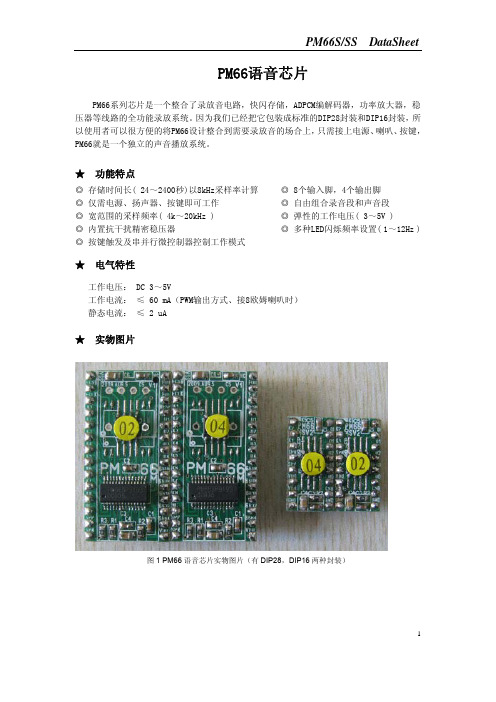
PM66S/SS DataSheet
引脚名称
B、DAC 方式:(示意图以三极管 8050 作为放大器件,用户可根据实际功率需求自行选 择功放器件)。 PM66S/PM66SS 芯片接线图如下图 2
图 2 并行按键模式,DAC 音频输出方式接线图 5
PM66S/SS DataSheet
C、 PM66+LM386 的典型电路(PM66 选用 DAC 模式输出)
⑸、 运行状态显示框
显示的内容:PM66 芯片的型号、载入或保存档案是否成功的提示、芯片烧写进度及故障信息提示。
⑹、 触发模式选项
PM66 芯片的触发模式:按键模式、串列位址(串行地址)模式及并列位址(并行地址)模式。(其它
三种模式为客户定制无需选择)
关于2262芯片简介

编码解码芯片PT2262/PT2272芯片原理简介:PT2262/2272是台湾普城公司生产的一种CMOS工艺制造的低功耗低价位通用编解码电路,PT2262/2272最多可有12位(A0-A11)三态地址端管脚(悬空,接高电平,接低电平),任意组合可提供531441地址码,PT2262最多可有6位(D0-D5)数据端管脚,设定的地址码和数据码从17脚串行输出,可用于无线遥控发射电路。
编码芯片PT2262发出的编码信号由:地址码、数据码、同步码组成一个完整的码字,解码芯片PT2272接收到信号后,其地址码经过两次比较核对后,VT脚才输出高电平,与此同时相应的数据脚也输出高电平,如果发送端一直按住按键,编码芯片也会连续发射。
当发射机没有按键按下时,PT2262不接通电源,其17脚为低电平,所以315MHz的高频发射电路不工作,当有按键按下时,PT2262得电工作,其第17脚输出经调制的串行数据信号,当17脚为高电平期间315MHz的高频发射电路起振并发射等幅高频信号,当17脚为低平期间315MHz的高频发射电路停止振荡,所以高频发射电路完全收控于PT2262的17脚输出的数字信号,从而对高频电路完成幅度键控(ASK调制)相当于调制度为100%的调幅。
PT2262/2272特点:CMOS工艺制造,低功耗,外部元器件少,RC 振荡电阻,工作电压范围宽:2.6~15v ,数据最多可达6位,地址码最多可达531441种。
应用范围:车辆防盗系统、家庭防盗系统、遥控玩具、其他电器遥控。
名称管脚说明A0-A111-8、10-13地址管脚,用于进行地址编码,可置为“0”,“1”,“f”(悬空),D0-D57-8、10-13数据输入端,有一个为“1”即有编码发出,内部下拉Vcc18电源正端(+)Vss9电源负端(-)TE14编码启动端,用于多数据的编码发射,低电平有效;OSC116振荡电阻输入端,与OSC2所接电阻决定振荡频率;OSC215振荡电阻振荡器输出端;Dout17编码输出端(正常时为低电平)在具体的应用中,外接振荡电阻可根据需要进行适当的调节,阻值越大振荡频率越慢,编码的宽度越大,发码一帧的时间越长。
- 1、下载文档前请自行甄别文档内容的完整性,平台不提供额外的编辑、内容补充、找答案等附加服务。
- 2、"仅部分预览"的文档,不可在线预览部分如存在完整性等问题,可反馈申请退款(可完整预览的文档不适用该条件!)。
- 3、如文档侵犯您的权益,请联系客服反馈,我们会尽快为您处理(人工客服工作时间:9:00-18:30)。
INPUT DATA CONTROL CIRCUIT
OUTPUT BUFFER
CHIP SELECT CSA 1 INPUT WRITE WEA 2 ENABLE INPUT OUTPUT OEA 4 ENABLE INPUT A7A A0A A 1A A 2A A 3A A 4A A5A A6A I/O0A I/O1A I/O2A I/O3A I/O4A I/O5A I/O6A I/O7A
SELECT INPUT WRITE 40 WEB ENABLE INPUT 38 OEB OUTPUT ENABLE INPUT
30 37 36 35 34 33 32 31 22 23 24 25 26 27 28 29
ROW/COLUMN DECODER
A PORT ADDRESS INPUT
21
GND
1
元器件交易网
MITSUBISHI 〈DIGITAL ASSP〉
M66222SP/FP
128 × 8-BIT × 2 MAIL-BOX
FUNCTION
The M66222 is a mail box most suitable for inter-MCU data communication interface. Provision of two pairs of addresses and data buses in its shared memory cell of 128 × 8-bit configuration allows independent and asynchronous read/write operations from/to two access ports of A and B individually. Two memory areas of 128 × 8-bit configuration are incorporated in the chip. Memory area (1) is used only to perform a write operation from A port and a read operation from B port, and memory area (2) only to perform a read operation from A port and a write operation from B port. In this case, address A7A should be set to “L” when writing data from A port in memory area (1), and address A7B should be set to “L” when reading data from B port in memory area (1). Also, address A7B should be set to “H” when writing data from B port in memory area (2), and address A7A should be set to “H” when reading data from A port in memory area (2). Therefore, an attempt to set addresses A7A and A7B from each port in a mode other than the above setting invalidates any read/write operation from the corresponding port (See Table 1 and Fig 1). As a basic write operation to memory, one of addresses A0 to A7 is specified. The CS signal is set to “L” to place one of I/O pins in the input mode. Also, the WE signal is set to “L”. Data at the I/O pin is written into memory.
As a read operation, the WE signal is set to “H”. Both CS signal and OE signal are set to “L” to place one of I/O pins in the output mode. One of addresses A0 to A7 is specified. Data at the specified address is thus output to the I/O pin. When the CS signal is set to “H”, the chip enters a non-select state which inhibits a read and write operation. At this time, the output is placed in the floating state (high impedance state), thus allowing OR tie with another chip. When the OE signal is set to “H”, the output enters the floating state. In the I/O bus mode, setting the OE signal to "H" at a write time avoids contention of I/O bus data. When the CS signal is set to Vcc, the output enters the full stand-by state to minimize supply current (See Tables 2 and 3).
7
A0A~A6A
ROW/COLUMN DECODER
A0B~A6B
7
A7B A0B A1B A2B A3B A4B A5B A6B I/O0B I/O1B I/O2B I/O3B I/O4B I/O5B I/O6B I/O7B
B PORT ADDRESS INPUT B PORT ES
• • • • • • • • • Memory configuration of 128 × 8 bits × 2 memory areas High-speed access, address access time 40ns (typ.) Complete asynchronous accessibility from ports A and B Fixed read/write access ports for memory Completely static operation Low power dissipation CMOS design 5V single power supply TTL direct-coupled I/O 3-state output for I/O pins
PIN CONFIGURATION (Top view)
CHIP SELECT CSA → INPUT WRITE ENABLE WEA → INPUT NC OUTPUT ENABLE OEA → INPUT A 0A → A 1A → A 2A → A PORT A3A → ADDRESS INPUT A 4A → A 5A → A 6A → A 7A → I/O0A ↔ I/O1A ↔ I/O2A ↔ ↔ A PORT I/O3A DATA I/O ↔ 4 A I/O I/O5A ↔ I/O6A ↔ I/O7A ↔ GND 1 2 3 4 5 6 7 8 9 10 11 12 13 14 15 16 17 18 19 20 21 42 VCC CHIP SELECT 41 ← CSB INPUT 40 ← WEB WRITE ENABLE INPUT NC 39 OUTPUT ENABLE 38 ← OEB INPUT 37 ← A0B 36 ← A1B 35 ← A2B 34 ← A3B B PORT ADDRESS 33 ← A4B INPUT 32 ← A5B 31 ← A6B 30 ← A7B 29 ↔ I/O7B 28 ↔ I/O6B 27 ↔ I/O5B 26 ↔ I/O4B B PORT DATA I/O 25 ↔ I/O3B 24 ↔ I/O2B 23 ↔ I/O1B 22 ↔ I/O0B