AWS_Dyn_WS_8_Response_Spectrum
3GPP标准
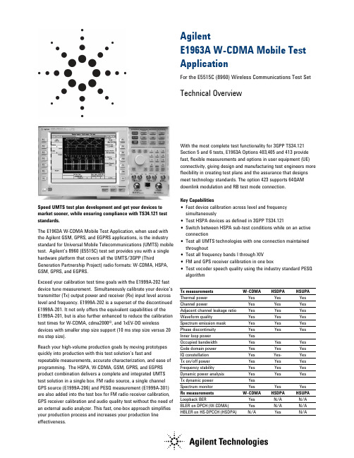
AgilentE1963A W-CDMA Mobile Test ApplicationFor the E5515C (8960) Wireless Communications Test Set Technical OverviewSpeed UMTS test plan development and get your devices to market sooner, while ensuring compliance with TS34.121 test standards.The E1963A W-CDMA Mobile Test Application, when used with the Agilent GSM, GPRS, and EGPRS applications, is the industry standard for Universal Mobile Telecommunications (UMTS) mobile test. Agilent’s 8960 (E5515C) test set provides you with a single hardware platform that covers all the UMTS/3GPP (Third Generation Partnership Project) radio formats: W-CDMA, HSPA, GSM, GPRS, and EGPRS.Exceed your calibration test time goals with the E1999A-202 fast device tune measurement. Simultaneously calibrate your device’s transmitter (Tx) output power and receiver (Rx) input level across level and frequency. E1999A-202 is a superset of the discontinued E1999A-201. It not only offers the equivalent capabilities of theE1999A-201, but is also further enhanced to reduce the calibration test times for W-CDMA, cdma2000®, and 1xEV-DO wireless devices with smaller step size support (10 ms step size versus 20 ms step size).Reach your high-volume production goals by moving prototypes quickly into production with this test solution’s fast and repeatable measurements, accurate characterization, and ease of programming. The HSPA, W-CDMA, GSM, GPRS, and EGPRS product combination delivers a complete and integrated UMTS test solution in a single box. FM radio source, a single channel GPS source (E1999A-206) and PESQ measurement (E1999A-301) are also added into the test box for FM radio receiver calibration, GPS receiver calibration and audio quality test without the need of an external audio analyzer. This fast, one-box approach simplifies your production process and increases your production line effectiveness. With the most complete test functionality for 3GPP TS34.121 Section 5 and 6 tests, E1963A Options 403,405 and 413 provide fast, flexible measurements and options in user equipment (UE) connectivity, giving design and manufacturing test engineers more flexibility in creating test plans and the assurance that designs meet technology standards. The option 423 supports 64QAM downlink modulation and RB test mode connection.Key Capabilities•Fast device calibration across level and frequency simultaneously•Test HSPA devices as defined in 3GPP TS34.121•Switch between HSPA sub-test conditions while on an active connection•Test all UMTS technologies with one connection maintained throughout•Test all frequency bands I through XIV•FM and GPS receiver calibration in one box•Test vocoder speech quality using the industry standard PESQ algorithmTx measurements W-CDMA HSDPA HSUPA Thermal power Yes Yes Yes Channel power Yes Yes Yes Adjacent channel leakage ratio Yes Yes Yes Waveform quality Yes Yes Yes Spectrum emission mask Yes Yes Yes Phase discontinuity Yes Yes Yes Inner loop power Yes Occupied bandwidth Yes Yes Yes Code domain power Yes Yes YesIQ constellation Yes Yes- YesTx on/off power Yes Yes Yes Frequency stability Yes Yes Yes Dynamic power analysis Yes Yes YesTx dynamic power YesSpectrum monitor Yes Yes YesRx measurements W-CDMA HSDPA HSUPA Loopback BER Yes N/A N/A BLER on DPCH (W-CDMA)Yes N/A N/A HBLER on HS-DPCCH (HSDPA)N/A YesN/A3GPP TS 34.121 Adherence3GPP TS34.121 Testdescription E1963A5.2 Maximum output power Yes(Release 5 only)5 5.2AA Maximum output power with HS-DPCCH(Release 6 and later)Yes55.2B Maximum output power with HS-DPCCH and E-DCHYes5 5.2C UE-relative code-domain power accuracy Yes5DPCCH and E-DCH55.3 Frequencyerror Yes5.4.1 Open loop power control Yes5.4.2 Inner loop power control Yes5.4.3 Minimum output power Yes5.4.4 Out-of-sync handling of output power E6703X2 5.5.1 Transmit off power Yes5.5.2 Transmit on/off time mask Yes5.6 Change of TFC E6703X5.7 Power setting in UL compressed mode5.7A HS-DPCCH Yes55.8 Occupied bandwidth (OBW)Yes5.9 Spectrum emission mask (SEM) Yes5.9A Spectrum emission mask with HS-DPCCH Yes5 5.9B Spectrum emission mask with E-DCH Yes5 5.10 Adjacent channel leakage power ratio (ACLR) Yes5.10A ACLR with HS-DPCCH Yes5 5.10B ACLR with E-DCH Yes5 5.11 Spuriousemissions Yes2 5.12 Transmitintermodulation Yes3 5.13.1 Error vector magnitude (EVM) Yes5.13.1A Error vector magnitude (EVM) with HS-DPCCH Yes5 5.13.1AA EVM and phase discontinuity with HS-DPCCH Yes5 5.13.2 Peak code domain error Yes5.13.2A Relative code domain error with HS-DPCCH Yes5.13.2B Relative code domain error with HS-DPCCH andE-DCHYes5.13.3 Phase discontinuity measurement Yes3GPP TS34.121 Testdescription E1963A/ E6703X6.2 Referencesensitivity Yes6.3 Maximum input level Yes 6.3A Maximum input level for HS-DPCCH reception(16QAM)Yes56.4 Adjacent channel selectivity (ACS)(Release 99 and Release 4)Yes1 6.4A ACS (Release 5 and later releases) Yes16.5 Blockingcharacteristics Yes16.6 Spuriousresponse Yes16.7 Intermodulationcharacteristics Yes16.8 Spuriousemissions Yes21 Requires use of external source2 Requires use of external spectrum analyzer3 Requires use of external spectrum analyzer and source4 Internal fading is possible using Baseband Studio. Most of these tests require external instrumentation such as faders. Consult TS34.121 for details.5 Requires Feature option license 3GPP TS34.121Test description E1963A7.2Demod in static propagation Yes7.3Demod in multi-path E6703X47.4Demod in moving channel E6703X47.5Demod in birth-death E6703X4What to Order for W-CDMA/HSPAModel number DescriptionE5515C8960 Series 10 Wireless Communications Test SetE5515C-003Flexible CDMA base station emulatorE1963A W-CDMA mobile test applicationE1963A-403HSDPA test modesE1963A-405E1963A-413HSDPA 14.4Mbps TMHSUPA test modesE1963A-423HSPA+ test modesWhat to Order for UMTSModel number DescriptionE5515C8960 Series 10 Wireless Communications Test SetE5515C-002Second RF sourceE5515C-003Flexible CDMA base station emulatorE1963A W-CDMA mobile test applicationE1963A-403HSDPA test modesE1963A-405HSDPA 14.4Mbps test modeE1963A-413HSUPA test modesE1963A-423HSPA+ test modesE1968A-202GSM/GPRS/EGPRS mobile test applicationE1987A Fast switching test applicationFeature Options List for W-CDMA/HSPA Model number DescriptionE1963A-401End-to-end videoE1963A-402Video loopbackE1963A-403HSDPA test modesE1963A-405HSDPA 14.4Mbps test modeE1963A-408Enhanced Audio (real-time vocoder, WB-AMR, DAI) E1963A-409Adv. SMSE1963A-413HSUPA test modesE1963A-423E1999A-202E1999A-206E1999A-301HSPA+ test modesEnhanced fast device tune measurementSingle channel GPS sourcePESQ MeasurementRelated LiteratureE1963A W-CDMA Test Application, photocard, 5989-3414ENAgilent 8960 Wireless Communications Test Set HSPA Applications, photocard, 5989-7515EN8960 Series 10 Wireless Communications Test Set, configuration guide, 5968-7873EFor More InformationLearn more about the E1963A test application and HSPA Options at:/find/E1963AFor details on the manufacturing test solutions visit:/find/8960mfg Technical SpecificationsThese specifications apply to an E5515C mainframe with Option 003 (or E5515B/T upgraded to equivalent configuration) when used with the latest E1963A test application or the E1987A test application.Specifications describe the test set’s warranted performance and are valid for the unit’s operation within the stated environmental ranges unless otherwise noted. All specifications are valid after a 30-minute warm-up period of continuous operation.Supplemental characteristics are intended to provide typical, but non-warranted, performance parameters that may be useful in applying the instrument. These characteristics are shown in italics and labeled as “typical” or “supplemental.” All units shipped from the factory meet these typical numbers at +25 °C ambient temperature without including measurement uncertainty. What Included in This Technical OverviewThis data sheet is organized in four sections:•HSPA Specifications•W-CDMA Specifications•HSPA and W-CDMA Common Technical Specifications •General SpecificationsHSPA/HSPA+ Specifications(E1963A Option 403, 405, 413 and 423)Call connection typesHSPA FDD test modeHSPA FDD test modes are supported by the E1963A. FDD test mode provides Layer 1 functionality only. No higher-level signaling is provided or accepted. No higher-level call processing operations are performed. The test set assumes that the user has appropriately configured the UE.FDD test mode allows you to test the parametric performance of your UE’s transmitter and receiver without call processing. In FDD test mode, the test set does not send any signaling information on the downlink. Rather, it continuously generates a downlink signal and searches for a corresponding uplink signal. The UE must synchronize to the downlink signal and send an appropriate uplink signal, which the test set uses to measure the UE’s transmitter and receiver performance. Any changes to the UE configuration must be accomplished by directly sending commands to the UE from a system controller through a proprietary digital interface./rfcomms/refdocs/wcdma/ wcdma_gen_bse_fddtest.phpFRC H-Set supportH-Set Modulation Nominal avg. inf. Bit rate (Mbps)2 QPSK, 16QAM 0.801, 1.1663 QPSK, 16QAM 1.601, 2.3324 QPSK 0.5345 QPSK 0.8016 QPSK, 16QAM 3.219, 5.6898 64QAM 13.25210 QPSK, 16QAM 4.68, 8.774HSPA RB test modeRB test mode uses signaling to establish a test control connection between the test set and UE, allowing you to test the parametric performance of your UE’s transmitter and receiver. In RB test mode, the test set provides signaling to establish a connection between the UE and the test set. The test set can also signal the UE to change its configuration and alter the uplink signal. The test set measures the uplink signal to determine the UE’s transmitter and receiver performance. RB test mode is operated on the downlink, simultaneously supporting a symmetrical RMC (Reference Measurement Channel) of 12.2 kbps. This symmetrical RMC is typically used for transmitter testing and receiver testing using BER./rfcomms/refdocs/wcdma/ wcdma_gen_bse_hsdpa_rbtest_setup.php HSPA handoversTo support the HSPA tests and sub-test conditions specified in the 3GPP standards, the Transport Channel Reconfiguration procedure allows you to change HSPA parameters while on a live connection. βc, βd, ∆ACK,∆NACK, ∆CQI, CQI feedback cycle (k), CQI repetition factor, Ack-Nack repetition factor, and default DPCH offset (DOFF) parameters can all be modified without dropping the HSPA connection. In addition, when using the user-defined DL configuration for HSDPA in RB test mode, the number of HARQ processes and UE IR buffer size can be changed on a live HSDPA connection to provide flexibility in testing multiple configurationsThe Radio Bearer Reconfiguration allows you to handover from a CS Domain or CS/PS Domain HSDPA RB Test Mode connection or HSPA RB Test Mode connection to a (non-HSDPA/non-HSPA) symmetrical RMC. The Radio Bearer Reconfiguration also allows you to change many other network parameters as part of the reconfiguration.You can also hand over between channels within a band and between bands using the Physical Channel Reconfiguration procedure. This allows you to test channels in the low, middle, and high frequency portions of each UE-supported band without dropping the HSPA connection./rfcomms/refdocs/wcdma/ wcdma_gen_call_handoffs.phpInter-system handoversAlmost all UEs support multiple formats today. To speed the process of testing multiple formats with call processing, you can perform handovers from HSPA to GSM and from HSPA to W-CDMA. If your test plan requires testing HSPA followed by GSM, GPRS, and/or EGPRS, you can hand over from an HSPA FRC to GSM test mode using the system handover. If your test plan requires testing W-CDMA as well, you can hand over from an HSPA FRC to a W-CDMA RMC, then use the existing W-CDMA RMC to GSM test mode system handover to test GSM, GPRS, and/or EGPRS./rfcomms/refdocs/wcdma/ wcdma_gen_call_handoffs.phpHSDPA user-defined downlinkVerify your device’s HSDPA throughput at the MAC-hs level with the user-defined downlink (DL) in the E1963A Option 403 and 405. Flexibly configure the 8960 to provide up to a 14.4 Mbps Radio Bearer (RB) test mode signal for testing HS-DSCH category 9 and 10 devices by setting the number of active HS-PDSCHs, transport block size index, modulation type, inter-TTI, number of HARQ processes, and UE incremental redundancy (IR) buffer size. HSPA+ option supports DL 64QAM and throughput is up to 21 Mbps./rfcomms/refdocs/wcdma/ wcdma_gen_bse_hsdpa_rbtest_setup.phpHSPA RF generatorW-CDMA channels active in HSPA modeW-CDMA(spread factor) Default assignmentAlternate choicesP-CCPCH (256) 1 --PICH (256) 16channel code settable within available coderangeDPCH, 12.2 kpbs RMC(128)20 HSDPA within available coderangeHS-SCCH-2 (128) 6 HS-SCCH-3 (128) 9 HS-SCCH-4 (128) 10 HS-PDSCH (16) 7OCNS HSDPA (128)122, 123, 124, 125, 126, 127HSUPA within available coderangeE-HICH (128) 22 E-RGCH (128) 22Common pilot channel relative level: -20 to 0 dBPrimary CCPCH relative level: -20 to 0 dB PICH relative level: -20 to 0 dBDPCH relative level : settable from -30 to 0 dB with 0.01 dB resolutionHS-SCCH relative level of individual code channels:HS-SCCH channel can be off but at least one channel is in presence. For 64QAM downlink, at least two channels are in presence. the channel level is settable from -20 to 0 dB HS-PDSCH relative level of all active code channels: settable from -20 to 0 dBPrimary sync channel relative level: always the same as P-CCPCHDownlink CDMA modulationModulation type: QPSK,16QAM and 64 QAM per 3GPP standard QPSK residual EVM : < 10%, typically < 3%QPSK carrier feed through: < -25 dBc , typically < -35 dBc nominal ambient performance: < -45 dBc 16QAM residual EVM: typically < 3%16QAM carrier feed through: typically < -35 dBc nominal ambient performance: < -45 dBcOCNS – orthogonal channel noise sourceComposed of 6 channels per Table E.5.5 in Annex E of 3GPP 34.121. OCNS channel can be off but at least 1 OCNS channel is in presence.OCNS channel relative level range: automatically calculated from other code channel relative levels to provide thecomposite W-CDMA cell power, but user-allocated channel level available./rfcomms/refdocs/wcdma/wcdma_gen_bse_gen_info.php#BCGCBAHEHSPA RF analyzer (measurements only) Real-time demodulation of: uplink– DPCH, HS-DPCCH, E-DCHTx measurementsChannel power measurementMeasurement bandwidthRRC filter off: measured with a bandwidth greater than (1 + α) * chip rate, where α = 0.22 and chip rate = 3.84 McpsRRC filter on:measured with a filter that has a root-raised cosine(RRC) filter response with roll-off α = 0.22 and a bandwidth equal to the chip rate 3.84 MHz BW centered on the active uplink channel)Measurement range:-61 to +28 dBm/3.84 MHzMeasurement interval: settable from 0.01 to 12 msMeasurement accuracy (at + 10 °C from the calibration temperature):< ±1.0 dB (typically < ±0.5 dB) for measurement intervals of 333 µs to12 ms over 698 to1024 MHz, 1400 to 1500 MHz and 1700 to 2000MHz< ±1.0 dB (typically < ±0.55 dB) for measurement intervals of 333 µs to12 ms over 2480 to 2580 MHz,< ±1.0 dB (typically < ±0.6 dB) for measurement intervals of 67 to < 333 µs over 698 to1024 MHz, 1400 to 1500 MHz and 1700 to 2000 MHz Measurement triggers: auto, immediate, protocol, RF rise, external, and HS-DPCCH/rfcomms/refdocs/wcdma/ wcdma_meas_chanpow_desc.php Phase discontinuityMeasurement method: the measured results include the phase discontinuity (defined as the phase difference of adjacent timeslots) as well as all waveform quality results for each timeslotInput power level range:Phase discontinuity: -61 to +28 dBm/3.84 MHzOther measurements: -25 to +28 dBm/3.84 MHzInput frequency ranges: 800 to 1000 MHz, 1700 to 1990 MHz Phase discontinuity range: ±180 degreesEVM range: 0 to 35% rmsPhase discontinuity measurement accuracy:< ±2.4 degrees (typically < ±1.7 degrees) for input levels of -25 to +28 dBm/3.84 MHz< ±2.6 degrees (typically < ±1.9 degrees) for input levels of -51 to < -25 dBm/3.84 MHzOther reported parameters with phase discontinuity: all measurements found in the waveform quality measurement are also available; the specifications are the same in both measurements, including the input power range of the waveform quality measurement Measurement interval: 617 µs (= 1 timeslot (667 µs) – 25 µs transient periods at either side of the nominal timeslot boundaries) or 283 µs (0.5 timeslot (333 µs) – 25 µs transient periods at either side of the nominal timeslot boundaries)Measurement triggers: protocol, external, and HS-DPCCH Temperature range: +20 to +55 °CConcurrency capabilities: phase discontinuity measurements cannot be made concurrently with other measurements/rfcomms/refdocs/wcdma/ wcdma_meas_wpdiscon_desc.phpWaveform quality measurement (HSDPA)Waveform quality measurement: composite EVMMeasurement format:HPSKMeasurement chip rate: 3.84 McpsInput level range: -25 to +28 dBm/3.84 MHzMeasurement range: < 35% EVMMeasurement interval: 0.5 to 1.0 timeslot with choice to include orexclude 25 µs transient periodsEVM measurement accuracy (including the effects of residualEVM):EVM measurement accuracy:< 2.8% rms, typically < 2.4% rms for UE EVM > 1% rms, < 2200 MHz< 3.2% rms, typically < 2.8% rms, for UE EVM > 1% rms, 2300 to 2580MHzMeasurement triggers: auto, protocol, immediate, external, and HS-DPCCHHS-DPCCH trigger alignment:adjustable oversubframes 0 to 5timeslots Ack Nack or CQIsubslots 0 to 0.5 timeslotOther reported parameters with EVM:•frequency error•magnitude error•phase error•origin offset•timing error•peak code domain errorFrequency error measurement range: ±1 kHzResidual frequency error:< ± (5 Hz + timebase accuracy) for a measurement interval of 1timeslot< ±(7 Hz + timebase accuracy) for a measurement interval of 0.5timeslotFrequency error measurement accuracy:Peak code domain error accuracy:< ±0.4 dB for code power levels > -25 dBTiming error measurement range: ±10 µsTiming error measurement accuracy: < ±0.5 chips (±130 ns)/rfcomms/refdocs/wcdma/wcdma_meas_wfrmqual_desc.php#CIHBBHDJIQ tuningAll measurements found in the waveform quality measurementare also available in the IQ tuning measurement; thespecifications are the same in both measurements./rfcomms/refdocs/wcdma/wcdma_meas_iqtuning_desc.phpHSPA Code domain powerCode domain power accuracy:< ±0.4 dB for code power level > -25 dBRelative code domain error (RCDE) accuracy:< ±0.5 dB for RCDE level > -20 dBRelative code domain power accuracy (RCDPA):< ±0.2 dB for code power level from ≥ -10 to 0 dB< ±0.3 dB for code power level from ≥ -15, -10 dB< ±0.4 dB for code power level from ≥ -20, -15 dBAll measurements found in the waveform quality measurement are also available in the code domain measurement; the specifications are the same in both measurements.Measurement triggers: immediate, protocol, external, auto, HS-DPCCH and Even Frame/rfcomms/refdocs/wcdma/ wcdma_meas_cod_dom_desc.phpAdjacent channel leakage ratio (ACLR) Measurement method:ratio of the filtered mean transmitted power to the filtered mean power in an adjacent channel; both the transmitted and the adjacent channel powers are measured with a filter that has a RRC response with roll-off α = 0.22 and a bandwidth equal to the chip rateInput power level range: +5 to +28 dBm/3.84 MHzInput frequency ranges: 698 to 1000 MHz, 1400 to 1500 MHz, 1700 to 2000 MHz, and 2480 to 2580 MHz,Measurement level ranging: autoMeasurement accuracy: < +0.8 dB (typically < +0.5 dB), including the effects of the residual floor, for measurements at -33 dBc at +5 MHz offsets and -43 dBc at +10 MHz offsets, and +10 °C from the calibration temperatureResidual ACLR floor: < -48 dBc for +5 MHz offsets, < -58 dBc for +10 MHz offsetsMeasurement triggers: auto, protocol, immediate, external, HS-DPCCH Trigger alignment: adjustable over subframes 0 to 5 Measurement interval: 1 timeslotMeasurement result: dBc relative to in-channel transmitted power /rfcomms/refdocs/wcdma/ wcdma_meas_aclr_desc.php Dynamic power analysisMeasurement method: graphical display of the uplink power waveform including HS-DPCCH, DPCH versus time; by using the HS-DPCCH trigger source, results will be aligned to the HS-DPCCHInput power level range: -61 to +28 dBm/3.84 MHz Measurement level ranging: autoData capture range: combination of number of steps and step length cannot exceed 58.26 msMeasurement bandwidth: selectable RRC filter on or offMeasurement interval: settable from 0.01 to 12 ms (must be less than or equal to the step length)Measurement accuracy: (at +10 °C from calibration temperature with measurement interval 333 µs to 12 ms):Input level range Measurement accuracy Frequency range < 25 dBtypically < ±0.5 dB 1700 to 2000 MHz< ±1.0 dB,typically < ±0.55 dB 2480 to 2580 MHz < 35 dBtypically < ±0.55 dB 1700 to 2000 MHz< ±1.0 dB,typically < ±0.6 dB 2480 to 2580 MHz< 40 dB typically < ±0.55 dB1700 to 2000 MHz< ±1.0 dB,typically < ±0.7 dB2480 to 2580 MHz Measurement triggers: RF rise, external, and HS-DPCCHHS-DPCCH trigger alignment:adjustable over subframes 0 to 5 /rfcomms/refdocs/wcdma/ wcdma_meas_wdpanalysis_desc.phpSpectrum emission mask (SEM)Measurement method: ratio of the transmitted power (3.84 MHz BW RRC) to offset frequencies, which are between 2.5 MHz and 12.5 MHz away from the UE center carrier frequency; the offset frequencies are measured in 30 kHz or 1 MHz bandwidths, depending on the offsetInput power level range:+5 to +28 dBm/3.84 MHzInput frequency ranges: 698 to 1000 MHz, 1400 to 1500 MHz, 1700 to 2000 MHz, and 2480 to 2580 MHzMeasurement accuracy:< +1.5 dB (typically < +0.8 dB) for the following offsets (+10 °C from the calibration temperature)8.5 to 12.5 MHz -49 1 MHz Measurement accuracy for additional spectrum emission limits for bands II, IV, V, X, XII, XIII and XIV:typically < +1.1 dB for the following offsets (+10 °C from the calibration temperature) Frequency offset Levels (dBm) Meas BW2.5 to3.5 MHz --15 dBm 30 kHz3.5 to 12.5 MHz -13 dBm or -15 dBm 1 MHz or 100 kHzMeasurement triggers:auto, protocol, immediate, external, and HS-DPCCHHS-DPCCH trigger alignment:adjustable over subframes 0 to 5 /rfcomms/refdocs/wcdma/ wcdma_meas_spec_em_mask_desc.php Rx measurementsHSDPA/HSPA+ block error ratioMeasurement method: test set counts the ACK/NACK/statDTX on UE HS-DPCCH and uses the results to calculate BLERBLER measurement input level range: -50 to +28 dBm/3.84 MHzReported parameters: measured BLER, number of blocks tested, throughput, number of ACKs, number of NACKs, number of stat DTXs, and median CQIConcurrency capability: HSDPA BLER measurements cannot be made concurrently with phase discontinuity, PRACH Tx on/off, or inner loop power measurements, or while speech is provided on the downlink; HSDPA BLER measurements can be made concurrently with all other measurements, including W-CDMA loopback BER and BLER/rfcomms/refdocs/wcdma/ wcdma_meas_hblerror_desc.phpHSDPA bit error ratioMeasurement method: the 8960 can be configured so that BER can be measured externally using the 8960 downlink and external UE monitoring softwareW-CDMA SpecificationsCall connection typesEnd-to-end video conferencing (Option 401)Loop back video conferencing (Option 402)Imaging testing real-time mobile video conferencing at your own desk!The E1963A, when configured as a two-instrument system, provides true H324 call setup with live video and audio from both mobile devices.With only one E5515C, Loop back video call can be setup with option 402.Validate compatibility by testing interoperability between your mobile and the competitor models offered for the same network.•complete call setup, mobile origination, and mobile release•64k circuit-switched UDI channel•H324 call setup/rfcomms/refdocs/wcdma/ wcdma_gen_call_video_call.phpAMR voiceStandard voice call with audio loopback for a quick check of voice functionality for 12.2 k rate; also many more AMR rates, such as 4.75, 5.15, 5.9, 6.7, 7.4, 7.95, 10.2, and 12.2 k•UE and BS origination 12.2 k•UE and BS release/rfcomms/refdocs/wcdma/ wcdma_gen_bse_amrvoice.phpFDD test modeFDD test mode allows you to test the parametric performance of your UE’s transmitter and receiver without call processing. In FDD test mode, the test set does not send signaling information on the downlink. Rather, it continuously generates a downlink signal and searches for a corresponding uplink signal. The UE must synchronize to the downlink signal and send and appropriate uplink signal, which the test set uses to measure the UE’s transmitter and receiver performance. Any changes to the UE configuration must be accomplished by directly sending commands to the UE from a system controller through a proprietary digital interface./rfcomms/refdocs/wcdma/ wcdma_gen_bse_fddtest.php RB test modeFast conformance test calls with significant configuration control and testing capabilities•BS origination and release•Symmetrical configuration: W-CDMA modes support symmetrical RMCs at 12.2, 64, 144 and 384 k rates.These symmetrical RMCs are typically used fortransmitter testing and receiver testing user BER (vialoopback type 1) or BLER (via loopback type 2) •Asymmetric configuration: the asymmetrical RMCs use either a 12.2 k channel or a 64 k channel on theuplink. The primary purpose of the symmetrical RMCsis to provide a way to make a BLER measurement bycounting retransmission requests that the UE sends.There is no need for data loopback in this mode /rfcomms/refdocs/wcdma/ wcdma_gen_bse_rbtest_setup.phpInter-system handoverDual-mode functionality is required for most W-CDMA phones, as GSM is an integral part in the majority of devices shipping today. Inter-system handovers provide a means to validate dual-mode performance at your desk instead of roaming on a real network. When operated in conjunction with compressed mode, this feature can very closely emulate the basics of a real handover as made on the network.•blind handovers from W-CDMA to GSM•configurable landing GSM cell•test control to GSM voice•W-CDMA AMR voice to GSM voice/rfcomms/refdocs/wcdma/ wcdma_gen_call_handoffs.php。
Sophos Firewall XGS 系列设备说明书

Sophos Firewall 强大的防护和性能Sophos Firewall 强大的防护和性能Sophos Firewall Xstream 架构设计提供极佳的可见性、防护和性能,帮助解决当前网络管理员面临的最大挑战。
TLS 1.3 检查现在约 99% 的 Web 流量加密,对大多数防火墙不可见。
许多组织发现,保护自己的网络防范越来越多的利用这一盲点的勒索软件、威胁和潜在有害应用程序时无能为力。
Sophos Firewall 能够实现高效且有效的 TLS 检查,不牺牲性能。
我们集成 Xstream Flow Processor 的 XGS 系列设备将 TLS 流量放在 FastPath 上以加速检查。
我们的高性能 TLS 检查引擎支持 TLS 1.3 而不降级,最新加密套件实现最大兼容性,同时增强了从仪表板检视加密流量的可见性。
深度数据包检查我们相信您再也不必在安全与性能之间取舍了。
Sophos Firewall 采用高速深度数据包检查 (DPI) 引擎扫描流量中的威胁,不使用减慢处理速度的代理。
防火墙堆栈可以将处理工作有效转移至 DPS 引擎,显著降低延迟,提高整体效率。
Sophos Firewall 通过高性能流传输 DPI 阻止最新勒索软件和外泄,包括下一代 IPS、Web 防护和应用程序控制,以及 SophosLabs Intelix 支持的深度学习和沙箱。
应用程序加速网络流量的很大一部分是受信任的业务应用程序流量,目的地是分支办事处、远程用户或云应用服务器。
因此,无需对威胁或恶意软件进行额外安全扫描,可以智能引导至 FastPath,减少延迟,优化整体性能,释放性能用于需要深度数据包检查的流量。
Sophos Firewall 自动或通过您自己政策加速您的 SaaS、SD-WAN 和云流量,如 VoIP、视频和其他受信任应用程序 – 放在 FastPath 上通过 Xstream Flow Processor。
aws alb用法
AWS Application Load Balancer (ALB) 用法简介AWS Application Load Balancer (ALB) 是一种负载均衡器,用于在应用程序层面上分发流量。
它能够根据请求的内容进行路由,将流量分发到不同的后端目标(如Amazon EC2 实例、容器、IP 地址或 Lambda 函数)。
ALB 还支持自动扩展,可根据流量需求自动添加或删除后端目标。
在本文中,我们将深入探讨 ALB 的用法,包括创建和配置 ALB、添加后端目标、配置监听器和目标组,以及使用 ALB 的高级功能。
创建和配置 ALB要创建 ALB,首先需要登录 AWS Management Console,并导航到 Elastic Load Balancing 服务。
在该服务下的“Load Balancers”页面,点击“Create Load Balancer”按钮。
步骤 1:选择负载均衡器类型在“选择负载均衡器类型”步骤中,选择“Application Load Balancer”。
ALB 可以在 OSI 模型的第七层(应用层)上工作,能够基于请求的内容进行路由。
步骤 2:配置负载均衡器在“配置负载均衡器”步骤中,需要设置以下参数:•负载均衡器名称:为 ALB 指定一个唯一的名称。
•方案:选择负载均衡器的方案,可以是 Internet-facing 或 Internal。
Internet-facing 负载均衡器可公开访问,而 Internal 负载均衡器仅限于VPC 内部访问。
•IP 地址类型:选择负载均衡器的 IP 地址类型,可以是 IPv4 或双栈(IPv4 + IPv6)。
•监听器:配置负载均衡器的监听器,后续会详细介绍。
步骤 3:配置安全组在“配置安全组”步骤中,为负载均衡器选择一个安全组。
安全组定义了负载均衡器的入站和出站流量规则。
步骤 4:配置目标组在“配置目标组”步骤中,需要设置以下参数:•目标组名称:为目标组指定一个唯一的名称。
德尔·韦玛网络S4048T-ON交换机说明书

The Dell EMC Networking S4048T-ON switch is the industry’s latest data center networking solution, empowering organizations to deploy modern workloads and applications designed for the open networking era. Businesses who have made the transition away from monolithic proprietary mainframe systems to industry standard server platforms can now enjoy even greater benefits from Dell EMC open networking platforms. By using industry-leading hardware and a choice of leading network operating systems to simplify data center fabric orchestration and automation, organizations can tailor their network to their unique requirements and accelerate innovation.These new offerings provide the needed flexibility to transform data centers. High-capacity network fabrics are cost-effective and easy to deploy, providing a clear path to the software-defined data center of the future with no vendor lock-in.The S4048T-ON supports the open source Open Network Install Environment (ONIE) for zero-touch installation of alternate network operating systems, including feature rich Dell Networking OS.High density 1/10G BASE-T switchThe Dell EMC Networking S-Series S4048T-ON is a high-density100M/1G/10G/40GbE top-of-rack (ToR) switch purpose-builtfor applications in high-performance data center and computing environments. Leveraging a non-blocking switching architecture, theS4048T-ON delivers line-rate L2 and L3 forwarding capacity within a conservative power budget. The compact S4048T-ON design provides industry-leading density of 48 dual-speed 1/10G BASE-T (RJ45) ports, as well as six 40GbE QSFP+ up-links to conserve valuable rack space and simplify the migration to 40Gbps in the data center core. Each40GbE QSFP+ up-link can also support four 10GbE (SFP+) ports with a breakout cable. In addition, the S4048T-ON incorporates multiple architectural features that optimize data center network flexibility, efficiency and availability, including I/O panel to PSU airflow or PSU to I/O panel airflow for hot/cold aisle environments, and redundant, hot-swappable power supplies and fans. S4048T-ON supports feature-rich Dell Networking OS, VLT, network virtualization features such as VRF-lite, VXLAN Gateway and support for Dell Embedded Open Automation Framework.• The S4048T-ON is the only switch in the industry that supports traditional network-centric virtualization (VRF) and hypervisorcentric virtualization (VXLAN). The switch fully supports L2 VX-• The S4048T-ON also supports Dell EMC Networking’s Embedded Open Automation Framework, which provides enhanced network automation and virtualization capabilities for virtual data centerenvironments.• The Open Automation Framework comprises a suite of interre-lated network management tools that can be used together orindependently to provide a network that is flexible, available andmanageable while helping to reduce operational expenses.Key applicationsDynamic data centers ready to make the transition to software-defined environments• High-density 10Gbase-T ToR server access in high-performance data center environments• Lossless iSCSI storage deployments that can benefit from innovative iSCSI & DCB optimizations that are unique only to Dell NetworkingswitchesWhen running the Dell Networking OS9, Active Fabric™ implementation for large deployments in conjunction with the Dell EMC Z-Series, creating a flat, two-tier, nonblocking 10/40GbE data center network design:• High-performance SDN/OpenFlow 1.3 enabled with ability to inter-operate with industry standard OpenFlow controllers• As a high speed VXLAN Layer 2 Gateway that connects thehypervisor based ovelray networks with nonvirtualized infrastructure Key features - general• 48 dual-speed 1/10GbE (SFP+) ports and six 40GbE (QSFP+)uplinks (totaling 72 10GbE ports with breakout cables) with OSsupport• 1.44Tbps (full-duplex) non-blocking switching fabric delivers line-rateperformance under full load with sub 600ns latency• I/O panel to PSU airflow or PSU to I/O panel airflow• Supports the open source ONIE for zero-touch• installation of alternate network operating systems• Redundant, hot-swappable power supplies and fansDELL EMC NETWORKING S4048T-ON SWITCHEnergy-efficient 10GBASE-T top-of-rack switch optimized for data center efficiencyKey features with Dell EMC Networking OS9Scalable L2 and L3 Ethernet switching with QoS and a full complement of standards-based IPv4 and IPv6 features, including OSPF, BGP and PBR (Policy Based Routing) support• Scalable L2 and L3 Ethernet switching with QoS and a full complement of standards-based IPv4 and IPv6 features, including OSPF, BGP andPBR (Policy Based Routing) support• VRF-lite enables sharing of networking infrastructure and provides L3traffic isolation across tenants• Increase VM Mobility region by stretching L2 VLAN within or across two DCs with unique VLT capabilities like Routed VL T, VLT Proxy Gateway • VXLAN gateway functionality support for bridging the nonvirtualizedand the virtualized overlay networks with line rate performance.• Embedded Open Automation Framework adding automatedconfiguration and provisioning capabilities to simplify the management of network environments. Supports Puppet agent for DevOps• Modular Dell Networking OS software delivers inherent stability as well as enhanced monitoring and serviceability functions.• Enhanced mirroring capabilities including 1:4 local mirroring,• Remote Port Mirroring (RPM), and Encapsulated Remote PortMirroring (ERPM). Rate shaping combined with flow based mirroringenables the user to analyze fine grained flows• Jumbo frame support for large data transfers• 128 link aggregation groups with up to 16 members per group, usingenhanced hashing• Converged network support for DCB, with priority flow control(802.1Qbb), ETS (802.1Qaz), DCBx and iSCSI TLV• S4048T-ON supports RoCE and Routable RoCE to enable convergence of compute and storage on Active FabricUser port stacking support for up to six units and unique mixed mode stacking that allows stacking of S4048-ON with S4048T-ON to providecombination of 10G SFP+ and RJ45 ports in a stack.Physical48 fixed 10GBase-T ports supporting 100M/1G/10G speeds6 fixed 40 Gigabit Ethernet QSFP+ ports1 RJ45 console/management port with RS232signaling1 USB 2.0 type A to support mass storage device1 Micro-USB 2.0 type B Serial Console Port1 8 GB SSD ModuleSize: 1RU, 1.71 x 17.09 x 18.11”(4.35 x 43.4 x 46 cm (H x W x D)Weight: 23 lbs (10.43kg)ISO 7779 A-weighted sound pressure level: 65 dB at 77°F (25°C)Power supply: 100–240V AC 50/60HzMax. thermal output: 1568 BTU/hMax. current draw per system:4.6 A at 460W/100VAC,2.3 A at 460W/200VACMax. power consumption: 460 WattsT ypical power consumption: 338 WattsMax. operating specifications:Operating temperature: 32°F to 113°F (0°C to45°C)Operating humidity: 5 to 90% (RH), non-condensing Max. non-operating specifications:Storage temperature: –40°F to 158°F (–40°C to70°C)Storage humidity: 5 to 95% (RH), non-condensingRedundancyHot swappable redundant powerHot swappable redundant fansPerformance GeneralSwitch fabric capacity:1.44Tbps (full-duplex)720Gbps (half-duplex)Forwarding Capacity: 1080 MppsLatency: 2.8 usPacket buffer memory: 16MBCPU memory: 4GBOS9 Performance:MAC addresses: 160KARP table 128KIPv4 routes: 128KIPv6 hosts: 64KIPv6 routes: 64KMulticast routes: 8KLink aggregation: 16 links per group, 128 groupsLayer 2 VLANs: 4KMSTP: 64 instancesVRF-Lite: 511 instancesLAG load balancing: Based on layer 2, IPv4 or IPv6headers Latency: Sub 3usQOS data queues: 8QOS control queues: 12Ingress ACL: 16KEgress ACL: 1KQoS: Default 3K entries scalable to 12KIEEE compliance with Dell Networking OS9802.1AB LLDP802.1D Bridging, STP802.1p L2 Prioritization802.1Q VLAN T agging, Double VLAN T agging,GVRP802.1Qbb PFC802.1Qaz ETS802.1s MSTP802.1w RSTP802.1X Network Access Control802.3ab Gigabit Ethernet (1000BASE-T)802.3ac Frame Extensions for VLAN T agging802.3ad Link Aggregation with LACP802.3ae 10 Gigabit Ethernet (10GBase-X) withQSA802.3ba 40 Gigabit Ethernet (40GBase-SR4,40GBase-CR4, 40GBase-LR4) on opticalports802.3u Fast Ethernet (100Base-TX)802.3x Flow Control802.3z Gigabit Ethernet (1000Base-X) with QSA 802.3az Energy Efficient EthernetANSI/TIA-1057 LLDP-MEDForce10 PVST+Max MTU 9216 bytesRFC and I-D compliance with Dell Networking OS9General Internet protocols768 UDP793 TCP854 T elnet959 FTPGeneral IPv4 protocols791 IPv4792 ICMP826 ARP1027 Proxy ARP1035 DNS (client)1042 Ethernet Transmission1305 NTPv31519 CIDR1542 BOOTP (relay)1812 Requirements for IPv4 Routers1918 Address Allocation for Private Internets 2474 Diffserv Field in IPv4 and Ipv6 Headers 2596 Assured Forwarding PHB Group3164 BSD Syslog3195 Reliable Delivery for Syslog3246 Expedited Assured Forwarding4364 VRF-lite (IPv4 VRF with OSPF, BGP,IS-IS and V4 multicast)5798 VRRPGeneral IPv6 protocols1981 Path MTU Discovery Features2460 Internet Protocol, Version 6 (IPv6)Specification2464 Transmission of IPv6 Packets overEthernet Networks2711 IPv6 Router Alert Option4007 IPv6 Scoped Address Architecture4213 Basic Transition Mechanisms for IPv6Hosts and Routers4291 IPv6 Addressing Architecture4443 ICMP for IPv64861 Neighbor Discovery for IPv64862 IPv6 Stateless Address Autoconfiguration 5095 Deprecation of T ype 0 Routing Headers in IPv6IPv6 Management support (telnet, FTP, TACACS, RADIUS, SSH, NTP)VRF-Lite (IPv6 VRF with OSPFv3, BGPv6, IS-IS) RIP1058 RIPv1 2453 RIPv2OSPF (v2/v3)1587 NSSA 4552 Authentication/2154 OSPF Digital Signatures Confidentiality for 2328 OSPFv2 OSPFv32370 Opaque LSA 5340 OSPF for IPv6IS-IS1142 Base IS-IS Protocol1195 IPv4 Routing5301 Dynamic hostname exchangemechanism for IS-IS5302 Domain-wide prefix distribution withtwo-level IS-IS5303 3-way handshake for IS-IS pt-to-ptadjacencies5304 IS-IS MD5 Authentication5306 Restart signaling for IS-IS5308 IS-IS for IPv65309 IS-IS point to point operation over LANdraft-isis-igp-p2p-over-lan-06draft-kaplan-isis-ext-eth-02BGP1997 Communities2385 MD52545 BGP-4 Multiprotocol Extensions for IPv6Inter-Domain Routing2439 Route Flap Damping2796 Route Reflection2842 Capabilities2858 Multiprotocol Extensions2918 Route Refresh3065 Confederations4360 Extended Communities4893 4-byte ASN5396 4-byte ASN representationsdraft-ietf-idr-bgp4-20 BGPv4draft-michaelson-4byte-as-representation-054-byte ASN Representation (partial)draft-ietf-idr-add-paths-04.txt ADD PATHMulticast1112 IGMPv12236 IGMPv23376 IGMPv3MSDP, PIM-SM, PIM-SSMSecurity2404 The Use of HMACSHA- 1-96 within ESPand AH2865 RADIUS3162 Radius and IPv63579 Radius support for EAP3580 802.1X with RADIUS3768 EAP3826 AES Cipher Algorithm in the SNMP UserBase Security Model4250, 4251, 4252, 4253, 4254 SSHv24301 Security Architecture for IPSec4302 IPSec Authentication Header4303 ESP Protocol4807 IPsecv Security Policy DB MIBdraft-ietf-pim-sm-v2-new-05 PIM-SMwData center bridging802.1Qbb Priority-Based Flow Control802.1Qaz Enhanced Transmission Selection (ETS)Data Center Bridging eXchange (DCBx)DCBx Application TLV (iSCSI, FCoE)Network management1155 SMIv11157 SNMPv11212 Concise MIB Definitions1215 SNMP Traps1493 Bridges MIB1850 OSPFv2 MIB1901 Community-Based SNMPv22011 IP MIB2096 IP Forwarding T able MIB2578 SMIv22579 T extual Conventions for SMIv22580 Conformance Statements for SMIv22618 RADIUS Authentication MIB2665 Ethernet-Like Interfaces MIB2674 Extended Bridge MIB2787 VRRP MIB2819 RMON MIB (groups 1, 2, 3, 9)2863 Interfaces MIB3273 RMON High Capacity MIB3410 SNMPv33411 SNMPv3 Management Framework3412 Message Processing and Dispatching forthe Simple Network ManagementProtocol (SNMP)3413 SNMP Applications3414 User-based Security Model (USM) forSNMPv33415 VACM for SNMP3416 SNMPv23417 Transport mappings for SNMP3418 SNMP MIB3434 RMON High Capacity Alarm MIB3584 Coexistance between SNMP v1, v2 andv34022 IP MIB4087 IP Tunnel MIB4113 UDP MIB4133 Entity MIB4292 MIB for IP4293 MIB for IPv6 T extual Conventions4502 RMONv2 (groups 1,2,3,9)5060 PIM MIBANSI/TIA-1057 LLDP-MED MIBDell_ITA.Rev_1_1 MIBdraft-grant-tacacs-02 TACACS+draft-ietf-idr-bgp4-mib-06 BGP MIBv1IEEE 802.1AB LLDP MIBIEEE 802.1AB LLDP DOT1 MIBIEEE 802.1AB LLDP DOT3 MIB sFlowv5 sFlowv5 MIB (version 1.3)DELL-NETWORKING-SMIDELL-NETWORKING-TCDELL-NETWORKING-CHASSIS-MIBDELL-NETWORKING-PRODUCTS-MIBDELL-NETWORKING-SYSTEM-COMPONENT-MIBDELL-NETWORKING-TRAP-EVENT-MIBDELL-NETWORKING-COPY-CONFIG-MIBDELL-NETWORKING-IF-EXTENSION-MIBDELL-NETWORKING-FIB-MIBIT Lifecycle Services for NetworkingExperts, insights and easeOur highly trained experts, withinnovative tools and proven processes, help you transform your IT investments into strategic advantages.Plan & Design Let us analyze yourmultivendor environment and deliver a comprehensive report and action plan to build upon the existing network and improve performance.Deploy & IntegrateGet new wired or wireless network technology installed and configured with ProDeploy. Reduce costs, save time, and get up and running cateEnsure your staff builds the right skills for long-termsuccess. Get certified on Dell EMC Networking technology and learn how to increase performance and optimize infrastructure.Manage & SupportGain access to technical experts and quickly resolve multivendor networking challenges with ProSupport. Spend less time resolving network issues and more time innovating.OptimizeMaximize performance for dynamic IT environments with Dell EMC Optimize. Benefit from in-depth predictive analysis, remote monitoring and a dedicated systems analyst for your network.RetireWe can help you resell or retire excess hardware while meeting local regulatory guidelines and acting in an environmentally responsible way.Learn more at/lifecycleservicesLearn more at /NetworkingDELL-NETWORKING-FPSTATS-MIBDELL-NETWORKING-LINK-AGGREGATION-MIB DELL-NETWORKING-MSTP-MIB DELL-NETWORKING-BGP4-V2-MIB DELL-NETWORKING-ISIS-MIBDELL-NETWORKING-FIPSNOOPING-MIBDELL-NETWORKING-VIRTUAL-LINK-TRUNK-MIB DELL-NETWORKING-DCB-MIBDELL-NETWORKING-OPENFLOW-MIB DELL-NETWORKING-BMP-MIBDELL-NETWORKING-BPSTATS-MIBRegulatory compliance SafetyCUS UL 60950-1, Second Edition CSA 60950-1-03, Second Edition EN 60950-1, Second EditionIEC 60950-1, Second Edition Including All National Deviations and Group Differences EN 60825-1, 1st EditionEN 60825-1 Safety of Laser Products Part 1:Equipment Classification Requirements and User’s GuideEN 60825-2 Safety of Laser Products Part 2: Safety of Optical Fibre Communication Systems FDA Regulation 21 CFR 1040.10 and 1040.11EmissionsInternational: CISPR 22, Class AAustralia/New Zealand: AS/NZS CISPR 22: 2009, Class ACanada: ICES-003:2016 Issue 6, Class AEurope: EN 55022: 2010+AC:2011 / CISPR 22: 2008, Class AJapan: VCCI V-3/2014.04, Class A & V4/2012.04USA: FCC CFR 47 Part 15, Subpart B:2009, Class A RoHSAll S-Series components are EU RoHS compliant.CertificationsJapan: VCCI V3/2009 Class AUSA: FCC CFR 47 Part 15, Subpart B:2009, Class A Available with US Trade Agreements Act (TAA) complianceUSGv6 Host and Router Certified on Dell Networking OS 9.5 and greater IPv6 Ready for both Host and RouterUCR DoD APL (core and distribution ALSAN switch ImmunityEN 300 386 V1.6.1 (2012-09) EMC for Network Equipment\EN 55022, Class AEN 55024: 2010 / CISPR 24: 2010EN 61000-3-2: Harmonic Current Emissions EN 61000-3-3: Voltage Fluctuations and Flicker EN 61000-4-2: ESDEN 61000-4-3: Radiated Immunity EN 61000-4-4: EFT EN 61000-4-5: SurgeEN 61000-4-6: Low Frequency Conducted Immunity。
4G优化案例:LTE数据业务感知时延异常根因分析案例

数据业务感知时延异常根因分析案例【摘要】造成现有数据网络感知时延有很多因素,如果所有因素全部平行排列评估很难找到主因,需要找到一个算法对现有问题进行逐层分析。
XX电信创新引入交叉关联法进行数据业务感知时延异常根因定位,并在福州进行试点应用,取得良好效果。
交叉关联法引用两个相关性最低的因子,结合聚类法进行主因判决,并利用增维法,逐步对问题进行剖析,最终定出影响感知时延最大的因素并进行解决。
【关键字】交叉关联分析法感知优化时延【业务类别】移动网一、背景伴随LTE 基站建设逐步进入后期,LTE 用户逐渐增多,网络优化工作的主要思路是如何更好的经营网络,工作重心也从指标优化转移到提升用户感知,特别是提升用户的上网感知,因此需要进一步挖掘网络潜力,优化现有网络配置,降低用户的网页浏览时延,从而提高用户的体验感知。
造成现有数据网络感知时延有很多因素,如果所有因素全部平行排列评估很难找到主因,需要找到一个算法对现有问题进行逐层分析。
XX电信创新引入交叉关联法进行数据业务感知时延异常根因定位,并在福州进行试点应用,取得良好效果。
该方法通过引用两个相关性最低的因子,结合聚类法进行主因判决,并利用增维法,逐步对问题进行剖析,最终定出影响感知时延最大的因素并进行解决。
二、交叉关联分析法基本原理2.1.交叉关联分析法基本原理交叉关联分析法又称立体分析法,是在纵向分析法和横向分析法的基础上,从交叉、立体的角度出发,多角度结合分析的方法,弥补了独立维度分析方法带来的偏差。
交叉关联分析涉及多维度的组合,表格比较容易把多个维度的交叉关系展现出来,因此在交叉分析中通常以表格为主。
我们平常看的表格通常叫做二维表,第一列设置为一个维度(如日期),表头罗列各类指标(把所有指标认为是一个维度—指标维),这样行列的两个维就组成了常见的二维表。
对二维表进行扩展,展现更加丰富的维度,在行列分层次放置多个维度,如下图所示:根据以上理论,我们针对目前高端到端时延小区进行交叉关联分析法进行定位,再通过不断增维层层分析定位问题小区的核心问题,最终通过相应优化方案调整解决。
Stratix 5700 EtherNet IP 训练工站说明书

Training WorkstationStratix 5700 EtherNet/IP WorkstationCatalog NumberMAJOR COMPONENTSPhoto shows ABT-TDENET5700 unit.Unit Dimensions• Width: 30 in (76 cm)• Height: 21 in (53 cm)• Depth: 13 in (33 cm)• Weight: Approx 45 lb (20 kg)Estimated Lead Time7 weeks. Some items are available for immediate shipment. Please call for availability.220-240V Plug OptionsSee the available document on Literature Library for 220-240V Plug Options for Workstations used in EMEA/AP (GMST10-PP524).Related ProductsThe workstation can be used in conjunction with the following products:• EtherNet/IP Procedures Guide (ABT-N300-TSJ50)• EtherNet/IP Fundamentals and Troubleshooting Lab Book (ABT-CCP180-TLB)• EtherNet/IP Configuration and Troubleshooting Lab Book (ABT-CCP183-TLB)†• Essentials of Industrial Ethernet Networks for an OT Professional Lab Book (ABT-CCP182-TLB)†• Essentials of Industrial Automation for an IT Professional Lab Book (ABT-CCP810-TLB)To use any of the lab books listed above with the ABT-TDENET5700-A workstation, the files provided for use with the PanelView Plus operator terminal will need to be updated.†Additional Hardware Required: The ABT-TD8300 Stratix 8300 workstation (or equivalent hardware) is required to complete some exercises in these lab books.Important Ordering Information*This unit is available with different PanelView Plus operator terminals:• For a unit with a PanelView Plus 6 terminal, order ABT-TDENET5700• For a unit with a PanelView Plus 7 terminal, order ABT-TDENET5700-AAllen-Bradley, CompactLogix, ControlLogix, expanding human possibility, PanelView Plus and Stratix are registered trademarks of Rockwell Automation Inc.Trademarks not belonging to Rockwell Automation are property of their respective companies.Publication GMST10-PP636F-EN-E – February 2020 | Supersedes Publication GMST10-PP636E-EN-E – October 2018Copyright © 2020 Rockwell Automation, Inc. All Rights Reserved. Printed in USA.To be respectful of the environment, Rockwell Automation is transitioning some of its training courses to a paperless format. Students are asked to complete downloads and bring personal devices to these classes. A full list of digital/paperless courses is currently available through your local distributor.。
ICT Spectrum8852培训

View Menu View Menu
Tab4_1 GUI- 8 3/10/2007
Testing Menu Testing Menu
Tab4_1 GUI- 9 3/10/2007
Tools Menu Tools Menu
System tools
四、Program debug
Discharge(>2uF)
Tab4_1 GUI- 20 3/10/2007
Right-click Channel field Right-click Channel field
Cap
Semiconductor
For most semiconductor junction tests, the above configuration is utilized. If choosing the longhand test type, select Test V Stim I.
TERADYNE
SPECTRUM-8852训练教材
斯比泰电子(嘉兴)有限公司
一、系统介绍--Hardware
Windows NT, LabWindows/CVI
高密度载板
PRISM analog ICT
Channel card
Channel card
Channel card
VP / VXI
FIB/DSCAN
Analyze/ Generate ASCII language program Wire list Drill file Inducer file Completed Fixture
Program database Completed Program
Flow
搜集资料
极限交换机VDX6740和VDX6740T产品介绍说明书
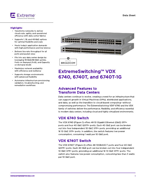
The VDX 674 0 T-1G ( Fig ure 3) offers 4 8 10 0 0 BA SE-T p ort s and t w o 4 0 Gb E QSFP+ p ort s. Each 4 0 Gb E p ort can b e b roken out int o four ind ep end ent 10 Gb E SFP+ p ort s, p rovid ing an ad d it ional eig ht 10 Gb E SFP+ p ort s for up link. A ll 4 8 10 0 0 BA SE-T p ort s can b e up g rad ed t o 4 8 10 GBA SE-T p ort s via t he Cap acit y on Dem and (CoD) soft w are license. Tw o 4 0 Gb E p ort s are enab led as p art of t he b ase license. The ad d it ional t w o 4 0 Gb E p ort s can b e up g rad ed via t he Port s on Dem and ( PoD) soft w are license.
- Meet s t od ay?s ap p licat ion d em and s w it h high perform ance and low latency
- Delivers line-rate t hroughput for all p ort s and p acket sizes
Dat a Sheet
- 1、下载文档前请自行甄别文档内容的完整性,平台不提供额外的编辑、内容补充、找答案等附加服务。
- 2、"仅部分预览"的文档,不可在线预览部分如存在完整性等问题,可反馈申请退款(可完整预览的文档不适用该条件!)。
- 3、如文档侵犯您的权益,请联系客服反馈,我们会尽快为您处理(人工客服工作时间:9:00-18:30)。
Inventory #002406 WS8-6
Workshop 8 – 环境
Workshop Supplement
Workbench-Simulation Dynamics
8.
对于PSD基础激励载荷,在Random Vibration分支 中,选择 >Insert>PSD Base Excitation 在PSD载荷的Details窗口中:
• 注意点:
– PSD分析的输出结果是1σ(1倍标准差)值(零均值),结果满足高斯分布. 可以解释为,在68.3%的 时间内,响应值会低于1倍标准差值. 2σ对应的是95.91% , 3σ对应的是99.737% . – 因为与方向有关的结果在本质上是统计性质的,因此不能像平常的方式进行组合. 例如,X、Y、Z方向 的位移不能够组合得到总体位移. 其它的导出量(如主应力)也一样. – 在>Solution>Solution Information下可以找到像参与因子和其它有用的输出
– 点击云图图例,添加和减少颜色等.
July 10, 2007 © 2007 ANSYS, Inc. All rights reserved.
ANSYS, Inc. Proprietary
Inventory #002406 WS8-12
Workshop 8 – 评述
Workshop Supplement
•
前处理的第一步是指定部件的材料 为钛合金. 在目录树中点击部件. 在 “Material”中,单击下拉菜单,点 击 >Import ,然后从Workbench 材料库中选择“Titanium Alloy”.
5. 6.
5
6
July 10, 2007 © 2007 ANSYS, Inc. All rights reserved.
Workbench-Simulation Dynamics
Scroll thru output text listing
July 10, 2007 © 2007 ANSYS, Inc. All rights reserved.
ANSYS, Inc. Proprietary
Inventory #002406 WS8-13
Workshop Supplement
Workbench-Simulation Dynamics
•
从“ WorkBench Project Launcher ”点击“ Simulation”。
–
•
如果进入“Simulation” ,点击 >File>New
基于培训,可以点击 “No: do not save any items”
12
July 10, 2007 © 2007 ANSYS, Inc. All rights reserved.
ANSYS, Inc. Proprietary
Inventory #002406 WS8-11
Workshop 8 – 评述
Workshop Supplement
•
记住:
– 模态振型的位移是相对的,并不是实际的位移. – 实际的位移幅值取决于输入能量的幅值和所施加的 谱. – 输入的PSD谱决定了响应幅值的大小.
1. 2. 改变 “Direction” 为 “Y”. 对于>Load Data,选择 >New PSD Load
9.
8
Acceleration (G2/Hz)
A2 A3
A1
A4
9
F1
F2
F3
F4
Frequency
July 10, 2007 © 2007 ANSYS, Inc. All rights reserved. ANSYS, Inc. Proprietary
1
3 4 2
July 10, 2007 © 2007 ANSYS, Inc. All rights reserved. ANSYS, Inc. Proprietary
15
Inventory #002406 WS8-4
Workshop 8 – 前处理
Workshop Supplement
Workbench-Simulation Dynamics
Acceleration (G2/Hz)
A2
A3
A1
固定端
A4
F1
F2F3F4Fra bibliotekANSYS, Inc. Proprietary
Frequency
July 10, 2007 © 2007 ANSYS, Inc. All rights reserved.
Inventory #002406 WS8-2
Workshop 8 – 起始页
– 这将在目录树中插入所有求解模态的 “Total Deformation”对象
12
July 10, 2007 © 2007 ANSYS, Inc. All rights reserved.
ANSYS, Inc. Proprietary
Inventory #002406 WS8-10
Workshop 8 – 随机振动结果
Inventory #002406 WS8-7
Workshop 8 -环境
Workshop Supplement
Workbench-Simulation Dynamics
•
PSD谱输入形式选择 “PSD G Acceleration” 和 “Table”. 点击 >OK. 输入表格数据. FREQ vs. G Acceleration.
•
注意: 点击工具条的求解,将会求解所有 的分支。 如果我们希望只求解一个分支的话,点击 相应的分支进行求解即可。
•
July 10, 2007 © 2007 ANSYS, Inc. All rights reserved.
ANSYS, Inc. Proprietary
Inventory #002406 WS8-9
Workbench-Simulation Dynamics
• 目的在于分析机翼在端部施加Y方向的加速度PSD谱 后的位移和应力. • PSD谱通过G Acceleration 指定. • PSD谱可以指定为加速度谱、速度谱、位移谱.
– 谱可以来自于实际的物理测量或者相应的规范指定. – 数据点可以以频率点和对应幅值的方式输入,或者表示 为一个方程.
Workshop Supplement
• •
现在查看随机振动结果. 可以插入如下结果 >Insert
– – – 1. 变形 Deformations 应变 Strains 应力 Stresses 在Details中指定为Z方向
RMB
10
Workbench-Simulation Dynamics
10. 选择>Insert>Deformation>Directional
•
点击 “ >Geometry>From File… ”,从相应文件夹中打开几何模型 文件 wing.iges
Note: This PSD could be performed as a continuation of the prior Wing Modal exercise if the dsdb had been saved to your harddrive. On a large complex “real” project, that might save a lot of time & effort. However, for this exercise, we will start again from scratch and import the geometry, assign material property, and insert the fixed boundary condition again.
反应谱 (PSD) 分析 机翼模型
Workshop 8
July 10, 2007 © 2007 ANSYS, Inc. All rights reserved.
ANSYS, Inc. Proprietary
Inventory #002406 WS8-1
Workshop 8 – 目的
Workshop Supplement
Workshop 8 – 求解
Workshop Supplement
Workbench-Simulation Dynamics
•
当所有分支准备完毕,即可求解随机振动 分析. 经过最后的校核,所有的分支的符号必须 是下面的一种:
– – (准备好) (完成)
•
11
11. 求解.
• 工具栏按钮 >Solve
1. 2. 在Details窗口中,单击“. 如有必要,使用 “Depth Picking” ,或者旋转模型.
7
8. 9.
8
9
Depth Picking
July 10, 2007 © 2007 ANSYS, Inc. All rights reserved.
ANSYS, Inc. Proprietary
July 10, 2007 © 2007 ANSYS, Inc. All rights reserved.
ANSYS, Inc. Proprietary
Inventory #002406 WS8-3
Workshop 8 – 设置
Workshop Supplement
Workbench-Simulation Dynamics
ANSYS, Inc. Proprietary
Inventory #002406 WS8-5
Workshop 8 – 环境