S7-300400 CPU之间的通信方式比较
S7-300 400的I Q区与PI PQ区的关系
S7-300/400的I/Q区与PI/PQ区的关系
S7-300/400的I/Q区称为过程映像输入区(PII)/过程映像输出区(PIQ),“映像”表示它们就像镜中花、水中月,访问它们并不是访问输入/输出模块,而是访问CPU存储器中的区域。
只是在过程映像区刷新的时刻,I区和Q区的内容才与输入/输出模块中的实际值相同,因此它们并不能直接反映输入/输出的实际状态。
S7-300/400的I/Q区与PI/PQ区(外设输入/外设输出区)的关系如下: 1)访问PI/PQ区时,直接读写输入/输出模块,而I/Q区是输入/输出模块在CPU的存储区中的“映像”。
使用外设地址可以实现用户程序与I/O模块之间的快速数据传送,因此被称为“立即读”和“立即写”。
在每次扫描循环开始时对P/Q区采用批量读/写的方式,因此造成了输入/输出的滞后。
2)I/Q区可以按位、字节、字和双字访问,PI/PQ区只能按字节(PIB/PQB)、字(PIW/PQW)和双字(PID/PQD)访问。
I/Q区和PI/PQ区可以使用相同的字节地址。
3)I/Q区的地址范围比PI/PQ区的小,有的S7-300CPU的I/Q区只有128B,有的CPU可以在组态时修改I/Q区的大小。
4)如果地址超出了I/Q区允许的范围,必须使用PI/PQ区来访问。
例如如果I/Q区只有128B,在访问S7-300的模拟量模块时(其地址区从256号字节开始),则必须使用PI/PQ区的地址。
S7-200与S7-300、400的以太网通讯

Entry ID:17369594Date:10/16/2003QUESTION:How do I configure an S7 connection for data communication between an S7-200 and an S7-300 via Ethernet?ANSWER:The configuration of an S7 connection between an S7-200 and an S7-300 via Ethernet has to be done on the onehand in STEP 7 Micro/WIN with the Ethernet Wizard for the S7- 200 and on the other in NetPro for the S7-300.For the Ethernet communication between the two stations you need communication processors and CPUs thatsupport S7 communication. In this entry we have explained all the settings required for the S7-200 and the S7-300 using a sample configuration with CPU 226, CP243-1, CPU 315-2DP and CP343-1.Configuration of the CP243-1 using the Ethernet Wizard of STEP 7 Micro/WINOpen STEP 7 Micro/WIN and then start the Ethernet Wizard via "Tools > Ethernet Wizard...".1.Fig. 1: Starting the Ethernet Wizard2. In the first step of the Wizard is a description of the Ethernet Wizard. Click on "Next" to startthe configuration process.Fig. 2: Description of the Ethernet Wizard3. In the window that is displayed you are informed that your STEP 7 Micro/WIN project must becompiled and be in Symbolic Addressing mode. Acknowledge the message with "Yes".Fig. 3: Compiling the project and enabling the Symbolic Addressing mode4. If you are connected with the CP243-1 in your S7-200 station, you can determine the moduleposition of the CP243-1 automatically via the "Read Modules" button. You can also enter themodule position manually. Click on "Next".Fig. 4: Determining the module position5. Define a unique IP address for the CP243-1 and specify the associated subnetwork mask.Acknowledge the settings with "Next".Fig. 5: Defining the IP address and subnetwork mask for the CP243-16. In our example we need an S7 connection for communication to the S7-300. So, for "Numberof connections to configure for this module" you enter "1". Click on "Next".Fig. 6: Number of S7 connections 7. The dialog for configuring the S7 connection opens. The S7 connection can be configured asa client or server connection. In our example we have used a client connection for the data transfer, i.e. the S7 connection is set up actively by the CP243-1.• Enter the TSAP for connection identification between the two stations. The first part of the TSAP (xx.) is taken from 10 + connection number , and the second part (.xx) of the TSAP istaken from the rack number and the slot of the CP343-1.In our example the TSAP is 10.07, i.e. the connection number = 0, the rack number = 0 and the slot of the CP = 7.• Enter the IP address of the CP343-1.•Specify a symbolic name for the connection. Click on the "Data Transfers" button to define a new data transfer for this connection.Fig. 7: Connection configuration8. In order to read data from the S7-300 you select "Read data from the remote serverconnection". Enter the number of data bytes to be read from the server and specify where thisdata is located in the S7-300. Define a storage area in the S7-200 for the data read. Assign asymbolic name for the data transfer. Acknowledge the settings with "OK".Fig. 8: Configuring the data transfer9. Since the configuration of the CP243-1 module may no longer be changed, you select thesetting with CRC protection. You can specify the Keep Alive Interval with the default time.Click on "Next".Fig. 9: CRC protection and Keep Alive Interval10. Select a free address area for storing the configuration.Fig. 10: Selecting a storage area for the configuration11. Close the Ethernet Wizard with "Finish". The Ethernet Wizard generates the projectcomponents required.Fig. 11: Closing the Ethernet Wizard12. In the main program ("MAIN (OB1)") you add the call of the ETH0_CTRL (communicationsetup) and the call of the ETH0_XFR (read data packages). The parameters "Chan_ID" and "Data" of the ETH0_XFR block can be selected with a right-click.Fig. 12: Adding the program code in the main program13. Save the configuration and load it in the S7 200.Configuring an unspecified S7 connection in NetPro1. Open your STEP 7 project with the configured SIMATIC S7-300 station and switch to NetProvia "Options > Configure Network".Fig. 13: Starting NetPro2. Mark the CPU in the SIMATIC S7-300 station and create a connection via "Insert > NewConnection...".Fig. 14: Inserting a new connection3. Select an unspecified S7 connection as connection type.Fig. 15: Creating an unspecified S7 connection4. The Properties Dialog for the S7 connection opens. Remove the check mark for "Establish anactive connection", because the connection is set up by the S7-200. For the partner address you enter the IP address of the S7-200. Then click on "Address Details...".Fig. 16: Properties of the S7 connection5. The partner TSAP settings must match the local settings in Fig. 7. However, the local TSAP iscalculated differently than for the S7-200. Local TSAP = 10 + Connection Number . RackNumber + Slot of the CPU. The correct TSAP in this mask is therefore 10.02.Fig. 17: Specification of the address details6. Save and compile the configuration. Then download the complete S7-300 station from NetPro.7. Switch to the block folder. Create DB11 with a sufficient data length, because this contains thedata for the communication (Fig. 8). Download this also into the controller.8. Configuration is now completed.You can now monitor the Receive data area (here: VB1000) online via the status table in STEP 7 Micro/WIN and check whether a data transfer is being made.更多资料请登陆工控世界论坛。
西门子S7-300与S7-400PLC相互之间的PROFIBUS-DP通讯

西门子S7-300与S7-400PLC相互之间的PROFIBUS-DP通讯西门子S7-300 与S7-400PLC 相互之间可以通过PROFIBUS-DP 方式进行通讯。
本文例子是一台CPU414-2DP 作为PROFIBUS-DP 通讯的主站,CPU315-2DP 作为PROFIBUS-DP 通讯的智能从站进行通信。
1. 硬件和软件要求硬件:1)PROFIBUS-DP 主站S7-400 CPU414-2DP;2)从站S7-300CPU315-2DP;3)带MPI 网卡CP5611 的编程计算机;4)PROFIBUS 电缆及接头。
软件:STEP7 V5.3。
把CPU414-2DP 集成的DP 接口和CPU315-2DP 集成的DP 接口连接起来,然后分别组态S7-300 站和S7-400 站,原则上先组态从站。
2. 网络组态及参数设置(1)组态从站1)新建项目:在STEP7 中创建一个新项目,点击右键,在弹出的菜单中选择Insert New ObjectSIMATIC 300 Station,插入S7-300 从站。
2)组态硬件:双击Hardware 选项,进入HWConfig 窗口。
点击Catalog 图标打开硬件目录,按硬件安装次序和订货号依次插入机架、电源、CPU 等进行硬件组态。
插入CPU 时会同时弹出PROFIBUS组态界面。
点击New 按钮新建PROFIBUS(1),组态PROFIBUS 站地址,本例中为6。
点击Properties 按钮组态网络属性,选择Network Setings 进行网络参数设置,在本例中设置PROFIBUS 的传输速率为1.5Mbit/s,行规为DP。
点击OK 按钮确认,出现PROFIBUS 网络。
双击CPU315-2DP 项下的DP 项,会弹出PROFIBUS-DP 的属性菜单。
①在网络属性窗口选择顶部菜单OperatingMode,选择DP slave 操作模式,如果其下的选择框被激活,则编程器可以对从站编程,也就是说这个接口即既以作为DP 从站,同时还可以通过这个接口监控程序。
以太网通信400与300单边通讯

以太网通信工业以太网Ethernet通讯(以一台S7-400、两台S7-300和一台MM420变频器的工业以太网单边通讯为例)1、新建项目1)、在SIMATIC Manager中新建一个项目,名称为“4-3-3-420”;硬件组态插入一个S7-400站和两个S7-300站。
如图4-1所示。
图4-12)、S7-400硬件组态时的参数设置。
图4-2插入CPU时会弹出网络属性窗口,新建以太网Ethernet(1),将以太网模板的IP地址设置为192.168.0.2,将网关点选为“使用路由器(U)”地址设置为192.168.0.7。
图4-3双击3号槽的CPU会弹出对话框,如图4-3。
将时钟存储器选项激活,存储器字节设置为“0”(MB0作为时钟信号)。
3)、S7-300(1)硬件组态时的参数设置。
图4-4组态变频器MM420参照西门子S7-300控制变频器MM420章节。
图4-5在插入以太CP时会弹出网络属性窗口,设置CP上以太网接口的网络参数。
以太网模板的IP地址设置为192.168.0.3,网关选择“使用路由器(U)”,地址自动生成为192.168.0.7。
如图1-5所示。
CUP属性窗口中,将时钟存储器选项激活,存储器字节设置为“0”(MB0作为时钟信号)。
参见图4-3。
4)、7-300(2)硬件组态时的参数设置。
参考S7-300(1)硬件组态时的参数设置。
在网络属性窗口中设置CP以太网接口的网络参数。
以太网模板的IP得知设置为198.168.0.4,网关选择“使用路由器(U)”,地址自动生成192.168.0.7。
CUP属性窗口中,将时钟存储器选项激活,存储器字节设置为“0”(MB0作为时钟信号)。
参见图4-3。
硬件组态完成后,分别进行编译、下载。
如果没有错误,接下来计入NetPro进行网络组态。
2、建立S7连接从SIMATIC Manager或HW Config点击网络组态按钮,进入NetPro进行网络组态。
S7-300和S7-400的CPU及性能指标

1.检索S7_300/400 CPU 型号及其主要性能指标。
S7300CPU 型号主要性能指标 CPU 312C 具有集成数字量I/O 以及集成计数功能的紧凑型CPUCPU 313C具有集成数字量和模拟量I/O 的紧凑型CPU CPU313C-2PTP 具有集成数字量I/O ,2个串口和集成计数功能的紧凑型CPUCPU 313C-2 DP具有集成数字量I/O, PROFIBUS DP 接口以及集成计数功能的紧凑型CPU CPU314C-2PTP具有集成数字量和模拟量I/O ,2个串口和集成计数,定位功能的紧凑型CPU CPU313C-2DP具有集成数字量和模拟量I/O ,PROFIBUS DP 接口和集成计数,定位功能的紧凑型CPUS7-400型号性能指标 CPU 412-1 满足中等规模的低成本方案,可用于具有少量I/O配置的较小型系统中具有组合的MP/DP 接口,可在PROFIBUS DP 网络中运行CPU 412-2 适用于中等性能范围的应用,它具有两个 PROFIBUSDP 出站系统CPU 414-2 为中等性能要求中的高需求而设计,可以满足对程序容量和处理速度有较高要求的应用,内置PROFIBUS DP 口,可以作为主站和从站直接连接到PROFIBUS DP 现场总线CPU 414-3 为中等性能要求中的高需求而设计,可以满足对程序容量和处理速度有较高要求的应用,内置PROFIBUS DP 口,可以作为主站和从站直接连接到PROFIBUS DP 现场总线CPU 414-3 PN/DP 为中等性能要求中的高需求而设计,可以满足对程序容量和处理速度有较高要求的应用,当使用ERTEC400-ASIC 时,具有交换机功能,它提供了可从外部接触到的两个PROFINET 端口,除分层网络拓扑结构之外,还可以在新型S7400控制器中创建总线型结构。
CPU 416-2 功能强大的SIMATIC S7-400 CPU 内置PROFIBUSDP 口,可以作为主站和从站直接连接到 PROFIBUSDP 现场总线,CPU 416-3 功能强大的SIMATIC S7-400 CPU 内置PROFIBUSDP 口,可以作为主站和从站直接连接到 PROFIBUSDP 现场总线,CPU 416-3 PN/DP 功能强大的SIMATIC S7-400 CPU 。
西门子S7300,400通信教程
送
站名、接收站名)送入环网传输。
令牌沿环网一周后返回发送站时,信息已被接收站拷贝,发送站
把令牌的状态为“空”,送入环网继续传输,以供其它站使用。
令牌传递总线能在重负荷下提供实时同步操作,传送效率高,适
于频繁,较短的数据传送。因此它更适合于需要进行实时通信的工
业
控制网络系统。
• 令牌环
令牌环传递类似于令牌总线,在令牌环上只能有一个令牌绕环运
6.2 通信标准 1 开放系统互连模型
国际化标准组织ISO提出的开放系统互连模型OSI。 作为通信网络国际标准化的参考模型。它详细描述了软件功能的7 个层次。
一类为面向用户的第5~7层,另一类为面向网络的第1~4层。
SIMATIC S7
Siemens AG 2000. All rights reserved.
SIMATIC S7
Siemens AG 2000. All rights reserved.
Date: 2019/4/29 File No.: SSP1_03C.13
Information and Training Center Knowledge for Automation
1 S7-300/400的通信网络
SIMATIC S7
Siemens AG 2000. All rights reserved.
Date: 2019/4/29 File No.: SSP1_03C.6
Information and Training Center Knowledge for Automation
• RS-485 RS-485是RS-422的变形。 半双工四线操作,一对平衡差分信号线不能同时发送和接收。
同步通信的格式: 同步通信以字节为单位,每次传送1~2个同步 字符,多个数据字节和校验字符。用同步字符通知接收方开始接 收。
以太网通信S7-1200 和 S7-300,400 (CE-X18) 间的数据交换
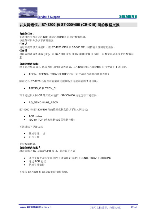
以太网通信:S7-1200 和 S7-300/400 (CE-X18) 间的数据交换
自动化任务:
可通过以太网在 S7-1200 和 S7-300/400 间进行数据传输。
该任务可以分为以下两种情况:
任务 A
通过集成的以太网接口,在 S7-1200 CPU 和 S7-300 CPU 间传输长度固定的数据。
任务B
通以太网通信处理器 (CP),在 S7-1200 CPU 和 S7-300 CPU 间传输一组数量可动态改变的数据元素。
自动化解决方案:
对于通过集成 CPU 以太网接口的开放式通信,S7-1200 和 S7-300/400 可包含以下 T 通信块:• TCON、TSEND、TRCV 和 TDISCON(可手动进行连接和断开连接)
除此之外,S7-1200 还包含带有集成连接和断开连接功能的 T 通信块:
• TSEND_C 和 TRCV_C
对于通过以太网 CP 的开放式通信,S7-300/400 还包含以下通信块:
• AG_SEND 和 AG_RECV
S7-1200 和 S7-300/400 间的数据交换支持以下以太网协议:
•TCP native
• ISO-on-TCP (动态数据长度的数据传输)
可通过以下寻址方式
•绝对寻址,或
•符号寻址
进行数据传输。
自动化解决方案 A
通过集成的 S7 -300er CPU 接口,通过以下方式
•通过带有手动连接管理的 T 通信块 (TCON, TSEND, TRCV, TDISCON)
•通过 TCP 协议
•绝对寻址数据
可实现 S7-1200 和 S7-300 间的数据传输。
图 01
图 02。
S7-300和S7-400集成PN口的S7通信
IA&DT Service & Support
Page 3-19
1. S7 通信简介
S7 通信是 S7 系列 PLC 基于 MPI、PROFIBUS、ETHERNET 网络的一种优化的通信协
议,主要用于 S7300/400PLC 之间的通信。SIMATIC S7- PN CPU 包含一个集成的
PROFINET 接口,该接口除了具有 PROFINET I/O 功能,还可以进行基于以太网的 S7 通
IA&DT Service & Support
Page 8-19
STATUS OUTPUT WORD I、Q、M、D、L
状态代码
S7-300: RD_1
S7-400: RD_i
(1 ≤ i ≤ 4)
IN_OUT
ANY
M、D、T、Z
I、Q、M、D、 T、Z
接收数据区
表 3 FB9 参数说明
同样,在 SIMATIC 315PN-2 的 OB1 中,调用 FB8/FB9。通信双方的“R_ID”均设为 0。
描述 上升沿触发工作
连接 ID 连接号,相同连接号的功能块互相
对应发送/接收数据
IA&DT Service & Support
Page 7-19
DONE OUTPUT BOOL ERROR OUTPUT BOOL
I、Q、M、D、L I、Q、M、D、L
STATUS OUTPUT S7-300:
SD_1 S7-400: IN_OUT
IA&DT Service & Support
Page 5-19
图4 然后双击该连接,设置连接属性。在“General”属性中块参数 ID = 1,这个参数即是下面 程序中的参数“ID”。在 SIMATIC 315PN-1 中激活“Establish an active connection”,作 为 Client 端,SIMATIC 315PN-2 作为 Server 端。
- 1、下载文档前请自行甄别文档内容的完整性,平台不提供额外的编辑、内容补充、找答案等附加服务。
- 2、"仅部分预览"的文档,不可在线预览部分如存在完整性等问题,可反馈申请退款(可完整预览的文档不适用该条件!)。
- 3、如文档侵犯您的权益,请联系客服反馈,我们会尽快为您处理(人工客服工作时间:9:00-18:30)。
S7-300/400 CPU之间的通信方式比较【工控老鬼】
1.基于MPI网络的全局数据通信
使用集成的MPI接口,不需增加通信用的硬件,只需组态,就可以实现周期性的数据交换。
传输的数据量较少,广播方式,可靠性较低。
2.基于MPI网络的S7基本通信
每个数据包最多76字节,不需要组态连接,调用SFC X_SEND、X_RCV、X_GET 与X_PUT实现通信,可用SFC断开连接。
3.S7通信
是专为S7和C7优化设计的通信协议,提供简明、强有力的通信服务。
可用于MPI、DP和以太网,最多可传送64K数据。
S7-300集成的通信接口在通信中只能作服务器,S7-400集成的DP接口和CP 443-5在单向S7通信中既可以作服务器,也可以作客户机。
它们之间还可以进行双向S7通信。
S7通信需要组态和编程。
4.DP主从通信
一台CPU作DP从站,需要组态双方用于通信的存储区,可能需要调用SFC14、SFC15来实现一致性数据传输。
5.S5兼容的通信
需要组态连接和调用AG_RECV、AG_SEND,最多240字节。
1)基于DP的FDL通信,需要使用通信处理器。
2)工业以太网中的ISO、ISO-on-TCP、TCP、UDP连接。
FDL和UDP可以采用多种通信方式。
6. 串行通信
双方需要使用串行通信处理器,通信速度低,极少使用。