韩国3S压力开关
HXD3C电器代号
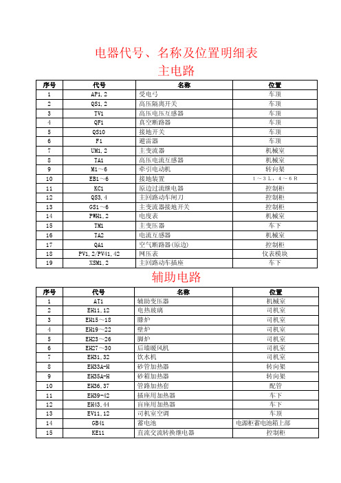
电器代号、名称及位置明细表主电路序号代号名称位置1 AP1,2 受电弓车顶2 QS1,2 高压隔离开关车顶3 TV1 高压电压互感器车顶4 QF1 真空断路器车顶5 QS10 接地开关车顶6 F1 避雷器车顶7 UM1,2 主变流器机械室8 TA1 高压电流互感器机械室9 M1~6 牵引电动机转向架10 EB1~6 接地装置1~3L,4~6R11 KC1 原边过流继电器控制柜12 QS3,4 主回路动车闸刀控制柜13 GS1~6 主变流器接地开关控制柜14 PWH1,2 电度表机械室15 TM1 主变压器车下16 TA2 电流互感器机械室17 QA1 空气断路器(原边) 控制柜18 PV1,2/PV41,42 网压表仪表模块19 XSM1,2 主回路动车插座车下辅助电路序号代号名称位置1 AT1 辅助变压器机械室2 EH11,12 电热玻璃司机室3 EH15~18 膝炉司机室4 EH19~22 壁炉司机室5 EH23~26 脚炉司机室6 EH27~30 后墙暖风机司机室7 EH31,32 饮水机司机室8 EH33A-H 砂管加热器转向架9 EH35A-H 砂箱加热器转向架10 EH36,37 管路加热套配管11 EH39-42 插座用加热器车下12 EH43,44 盲座用加热器车下13 EV11,12 司机室空调车顶14 GB41 蓄电池电源柜蓄电池箱上部15 KE11 直流交流转换继电器控制柜16 KM11,12 辅电源负载接触器控制柜17 KM13,14 空压机接触器控制柜18 KM15,16 空压机转换接触器控制柜19 KM20 辅电源负载转换接触器控制柜20 KM21 交流加热接触器控制柜21 KM22 直流加热接触器控制柜22 LC LC滤波装置机械室23 MA11~16 牵引通风机电机机械室24 MA17,18 复合冷却器风机电机机械室25 MA19,20 空气压缩机电机机械室26 MA21,22 油泵主变压器27 PV71 电压表控制柜28 QA11~16 牵引通风机空气断路器控制柜29 QA17,18 复合冷却器风机空气断路器控制柜30 QA19,20 空压机空气断路器控制柜31 QA21,22 油泵空气断路器控制柜32 QA23,24 司机室空调空气断路器控制柜33 QA25 辅助变压器空气断路器控制柜34 QA31A,B 司机室加热空气断路器控制柜35 QA32 电热玻璃空气断路器控制柜36 QA33 饮水机空气断路器控制柜37 QA56 空气断路器(直流加热)控制柜38 QA59 控制接地空气断路器控制柜39 QA61 蓄电池空气断路器控制柜40 QA72 空气断路器(交流加热)控制柜41 QA73 空气断路器(砂管加热)控制柜42 QA74 空气断路器(CM保温)控制柜43 QS11 辅助回路库用闸刀控制柜44 R71,72 接地电阻控制柜45 SA11,12 司机室加热开关操纵台右下46 SA13,14 电热玻璃开关操纵台右下47 UA11,12 辅助变流器机械室48 UC 110V充电装置电源柜蓄电池箱上部49 XSA1 辅助回路库用插座车下50 XSA3,4 司机室插座操纵台右下51 XSC3 充电插座车下52 YV96 砂管加热电磁阀制动单元控制电路序号代号名称位置1 AC41,42 司机控制器操纵台2 AE41 TCMS机械室3 AX1 机车安全信息综合监测装置ATP框4 BV41~46 电机速度传感器车下5 BV47,48 机车速度传感器2R,5L6 BV51~56 防滑传感器1~3R,4~6L7 BX1 电子标签车下8 CZ1~4 重联插头(插座)車端1L9 Dryer1,2 加热器(干燥器)机械室10 EL41~44 司机室灯司机室11 EL45~52 机械室灯机械室12 EL53,54 记点灯仪表模块13 EL55~58 标志灯车端两侧14 EL59~62 副照灯车端两侧15 EL63,64 前照灯车端上部16 EL65,66 仪表灯仪表模块17 EL67~70 车底灯车下18 EV13,14 空调控制箱司机室后墙内部19 EV21,22 记点灯电源操纵台内部20 EV31 数模转换盒ATP框21 EV33 自动过分相装置机械室22 EV34 二极管控制柜23 EV35,36 时间继电器控制柜24 EV41,42 显示屏稳压电源装置操纵台内部25 HL21,22 八灯显示器驾驶座左26 KE13,14 中间继电器控制柜27 KE15,16 EBV控制继电器控制柜28 KE17,18 升弓隔离控制继电器控制柜29 KE19 踏面清扫控制继电器控制柜30 KE20 控制继电器控制柜31 KE25 中间继电器控制柜32 KE21 紧急制动控制继电器控制柜33 KMC1 辅助压缩机接触器控制柜34 KP41~46 牵引通风机风道继电器风道35 KP47,48 复合冷却器风机风道继电器风道36 KP49,50 主变压器油流继电器主变压器37 KP51-1 压力开关配管38 KP51-2 压力开关配管39 KP52 主变压器油温检测继电器主变压器40 KP57 辅助压缩机压力开关制动单元41 KP58 压力开关制动单元42 KP59 压力开关配管43 KP60,61 压力开关配管44 L91~94 机车感应线圈车体装配45 LCDM1,2 制动显示屏仪表模块46 MD41,42 刮雨器水泵操纵台内部47 MD43,44 刮雨器正面窗48 MD45,46 遮阳帘正面窗49 MD47~50 司机室风扇司机室天棚50 MD51,52 冰箱操纵台内部51 MD53 辅助压缩机电机制动单元52 P1,2 速度表仪表模块53 PD41,42 微机显示屏仪表模块54 PD43,44 故障指示灯仪表模块55 PDU1,2 主断控制器控制装置在室内56 PS1 ATP监控装置ATP框57 PS2 信号主机ATP框58 PS3,4 监控显示屏仪表模块59 PS5,6 语音箱仪表模块60 PS7 信号接线盒ATP框61 PS9,10 机车重联电话司机室62 QA102 空气断路器(司机室门)控制柜63 QA104,105 司机室空调控制空气断路器控制柜64 QA106 空气断路器(充电装置)控制柜65 QA41,42 空气断路器(TCMS控制1,2)控制柜66 QA43,44 空气断路器(主控制回路1,2)控制柜677 QA45 空气断路器(控制回路)控制柜68 QA46 空气断路器(CI控制)控制柜69 QA47 空气断路器(APU控制)控制柜70 QA48 空气断路器(室内灯)控制柜71 QA49 空气断路器(車外灯)控制柜72 QA50 空气断路器(前灯)控制柜73 QA51 空气断路器(辅助回路)控制柜74 QA53 空气断路器(車内信号显示)控制柜75 QA54 空气断路器(ATP装置)控制柜76 QA55 空气断路器(制动装置)控制柜77 QA57 空气断路器(仪表灯)控制柜78 QA71 空气断路器(自动过分相)控制柜79 SA101,102 脚踏开关驾驶座80 SA103,104 紧急制动按钮开关装在电压表的右侧81 SA49,50 钥匙开关操纵台82 SA61,62 刮雨器转换开关操纵台右下83 SA65,66 司机室风扇开关操纵台右下84 SA69,70 冰箱转换开关操纵台右下85 SA73,74 空调控制开关操纵台右下86 SA75 CI试验转换开关控制柜87 SA83,84 撒砂脚踏开关驾驶座88 SA85,86 风笛脚踏开关驾驶座89 SA96 受电弓隔离转换开关控制柜90 SA97,98 监控故障隔离开关操纵台91 SA99,100 停放制动开关驾驶座92 SB41,42 受电弓扳键开关操纵台93 SB43,44 主断扳键开关操纵台94 SB45,46 空压机扳键开关操纵台95 SB47,48 司机室灯扳键开关操纵台96 SB49,50 机械室灯扳键开关操纵台97 SB51,52 标志灯扳键开关操纵台98 SB53,54 副照灯扳键开关操纵台99 SB55,56 前照灯扳键开关操纵台100 SB57,58 车底灯/仪表灯扳键开关操纵台101 SB61,62 复位按钮开关操纵台102 SB67,68 自动过分相按钮开关操纵台103 SB69,70 定速按钮开关操纵台104 SB75,76 遮阳帘转换开关操纵台右下105 SB81,82,85,86 风笛按钮开关操纵台106 SB95 辅助压缩机按钮开关控制柜107 SB96,97 司机控制器上死人开关司控器操纵盘108 SB99 监控解锁按钮开关操纵台109 SP1,2,3 压力传感器制动单元110 T1~T4 自动过分相装置传感器车下111 VAR4,5 压敏电阻控制柜112 VAR6,7 压敏电阻控制柜113 XL1,2 手提灯插座机械室114 XSC1,2 行灯插座车下115 YV101~106 防滑电磁阀机械室116 YV240,241 撒砂电磁阀制动单元117 YV41,42 受电弓电磁阀机械室118 YV50 停放制动电磁阀制动单元119 YV81,82 风笛电磁阀机械室120 YV83,84 风笛电磁阀机械室121 YV94 紧急制动电磁阀制动单元122 YV95 踏面清扫电磁阀制动单元123 无线列调无线装置箱HXD3C型电力机车高、低压试验程序及要求HXD3C型电力机车高、低压试验程序及要求一、低压试验前的准备工作1、闭合控制电器柜控制接地自动开关QA59,蓄电池自动开关QA61,确认控制电器柜上电压表PV71显示不低于98V。
南方某电厂#5锅炉汽包水位低低MFT事件技术分析

南方某电厂#5锅炉汽包水位低低MFT事件技术分析摘要文章通过对南方某电厂200MW机组锅炉汽包水位低低MFT事件进行分析,得出机组日常维护、保护设置及事故隐患排查时注意事项,为后续的机组安全运行提供科学指导及依据。
简介南方某电厂#5锅炉型号为HG-680/13.7-YM2型锅炉,是为以煤代油热电联产工程设计的,设计煤种为烟煤,锅炉为超高压参数,带一次中间再热的单锅筒自然循环、固态排渣、四角切圆燃烧、平衡通风、露天布置。
锅炉运行方式以冷凝工况为主,同时满足抽汽工况参数。
炉膛水平切面积为11660×11660mm2(宽×深),锅炉高度为40000mm。
关键词:200MW机组;汽包水位;分析;日常维护;保护设置;事故隐患排查一、事件经过2023年9月30日20时40分,#5机组正常运行,机组负荷191MW,汽包水位+4mm,给水流量545t/h,A、B、C、D、E磨运行,B电动给水泵运行。
20时40分39秒:B电动给水泵例外报告画面发B给水泵润滑油压低低报警,1秒后消失,反复三次后,于20时40分52秒持续发出滑油压低低报警。
20时40分58秒:B电动给水泵事故跳闸,3秒后A电动给水泵联锁启动。
A电动给水泵勺管开大至82%,转速升至5318转,总给水流量降至74/h后回升至273/h,汽包水位持续下降至-252mm。
20时41分45秒:#5锅炉MFT保护动作,跳闸首出为汽包水位低低,联跳#5汽轮机,程跳逆功率跳#5发电机,#5机组解列脱网。
当班控长下令按停机操作将机组安全停运。
21时00分,当值值长下令极热态启动#5机组。
10月1日02时08分,#5机组并网,04时45分加负荷至140MW,投入AGC,交系统调度。
二、检查情况DCS显示#5机B电动给水泵事故跳闸首出为润滑油压力低,经现场检查B电动给水泵无漏油现象,液力耦合器出口润滑油压力表显示为0.21MPa,未发现异常。
经检查逻辑B电动给水泵润滑油压低低压力开关(定值≤0.051MPa)动作,联跳B电动给水泵。
SOR压力开关样本
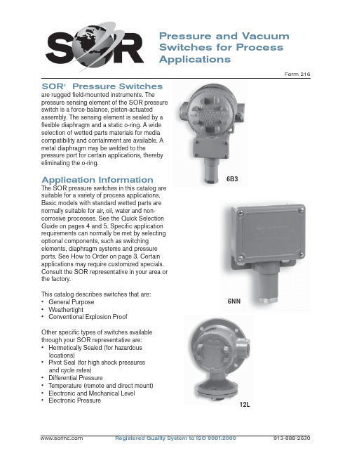
Pressure and Vacuum Switches for Process ApplicationsForm 216SOR ® Pressure Switchesare rugged fi eld-mounted instruments. Thepressure sensing element of the SOR pressure switch is a force-balance, piston-actuated assembly. The sensing element is sealed by a fl exible diaphragm and a static o-ring. A wide selection of wetted parts materials for media compatibility and containment are available. A metal diaphragm may be welded to thepressure port for certain applications, thereby eliminating the o-ring.Application InformationThe SOR pressure switches in this catalog are suitable for a variety of process applications. Basic models with standard wetted parts are normally suitable for air, oil, water and non-corrosive processes. See the Quick Selection Guide on pages 4 and 5. Specifi c application requirements can normally be met by selecting optional components, such as switching elements, diaphragm systems and pressure ports. See How to Order on page 3. Certain applications may require customized specials. Consult the SOR representative in your area or the factory.This catalog describes switches that are: • General Purpose • Weathertight• Conventional Explosion ProofOther specifi c types of switches available through your SOR representative are:• Hermetically Sealed (for hazardous locations)• Pivot Seal (for high shock pressuresand cycle rates)• Differential Pressure• Temperature (remote and direct mount)• Electronic and Mechanical Level • Electronic Pressure12L6B36NNFeatures SwitchesComplete Product LineStandard models and customized specials cover pressure range from30 inches Hg VAC to 4000 psi.Robust ConstructionRugged, high-cycle rate tolerance, long life, not critical to vibration, high overrange and proof pressures, excellent corrosionresistance to hostile environments. Instrument QualityHigh resolution of Set Points, high repeatability, narrow dead band,negligible temperature effect.Wetted PartsWide selection materials, process connection confi gurations and sizes.Optional “fi re-safe” pressure sensor.Snap-Action Electrical SwitchingWide selection UL Listed and CSA Certifi ed switching elements for ACand DC service. Optional “hermeticallysealed” capsule for hazardous and hostile environments.Field AdjustableSelf-locking adjustment, no special tools required. No-charge factory calibration.Cost EffectiveSimple and fast installation without special tools, long service life, norequired periodic service or spareparts.UL Listed, CSA Certifi ed, ATEXCertifi ed, FM, JIS/RIIS Approved ModelsMeets most code and customer requirements.Built-In QualityRigid quality standards maintained from raw material to fi nished product.ServiceFactory sales engineers and area SOR representatives provideeffective and prompt worldwideservice.DeliveryRoutine shipments 7 to 10 working days. Emergency shipments via sameday air.Warranty3 years from date of manufacture.Quick Selection GuideBasic SOR pressure switches with standard wetted parts are normally suitable for air, oil, water and non-corrosive processes. The Quick Selection Guide on pages 4 and 5 shows these basic SOR pressure and vacuum switches. Corrosive service and particular customer requirements may require optional components. Refer to How to Order section below to build a customized model number or the dedicated page to locate optional components, such as switching elements, diaphragm systems, pressure ports and accessories. Each position in the model number, except Accessories, must have a designator.Design and specifi cations are subject to change without notice. For latest revision, see .6NN-K5-M4-C2A-YYModel Number SystemDiaphragmHousingPistonSwitching Element Range SpringPressure PortAccessoriesApplicationsSOR pressure switches in this catalog are suitable for a wide variety of continuous pressure applications. Specifi c application requirements can normally be met by selecting optional components, such as, switching elements, diaphragm systems and pressure ports. Certain applications may require customized specials. Consult the SOR representative in your area or the factory.How to OrderInformation and data in this catalog are formatted to provide a convenient guide to assistinstrument engineers, plant engineers and end users in selecting pressure switches for their unique applications.Steps 1 through 5 are required. Step 6 is optional. Orders must have complete Model Numbers, i.e. each component must have a designator.Step 1: Select Piston-Spring adjustable range/Set Point from Specifi cations (pages 7 & 8). (Piston/Spring combination determines adjustable range.)Step 2: Select Housing for type of pressure switch and service (page 9).Step 3: Select electrical Switching Element for electrical service (pages 10 & 11).Step 4: Select Diaphragm and O-Ring for process compatibility and containment (pages 12 & 13).Step 5:Select Pressure Port for process compatibility and connection (page 14).Step 6: Select Accessories required for service (page 16).How to OrderSwitchesExplosion ProofWeathertightBasic SOR pressure switches with standard wetted parts are normally suitable for air, oil, waterand non-corrosive processes. Corrosive service and particular customer requirements may require optional components. Refer to How to Order on page 3 to locate optional components, such as, housing, switching elements, diaphragm systems, pressure ports and accessories. Each position in the model number, except Accessories, must have a designator.WeathertightExplosion ProofStandard Construction• Housing: NN - aluminum; L - cast iron• Switching Element: SPDT; N - 10 amps @ 250 VAC; K - 15 amps @ 250 VAC• Diaphragm & O-ring: N4 - primary (wetted)diaphragm, TCP; o-ring (wetted) Buna-N• Pressure Port: 1/4” NPT(F); B1A - aluminum; F1A - carbon steelNotes1. See balance of catalog for construction options.2. Dead band values are expressed as typical expected at mid-range for a particular model number. See Dead Band Considerations on page 8.3. Design and specifi cations subject to changewithout notice. For latest revision, see.Standard Construction• Housing: NN - aluminum; L - cast iron• Switching Element: SPDT; K - 15 amps @ 250 VAC• Diaphragm & O-ring: N4 - primary (wetted)diaphragm, TCP; o-ring (wetted) Buna-N• Pressure Port: 1/4” NPT(F); B1A - aluminum; F1A - carbon steelNotes1. See balance of catalog for construction options.2. Dead band values are expressed as typical expected at mid-range for a particular model number. See Dead Band Considerations on page 8.3. Design and specifi cations subject to change without notice. For latest revision, see .WeathertightExplosion ProofExplosion ProofWeathertightStandard Construction• Housing: NN - aluminum; L - cast iron• Switching Element: SPDT; K - 15 amps @ 250 VAC • Diaphragm & O-ring: N4 - primary (wetted) diaphragm, TCP; o-ring (wetted) Buna-N. Piston 56 primary (wetted) diaphragm, 316SS.• Pressure Port: 1/4” NPT(F); B1A - aluminum; F1A - carbon steelNotes1. See balance of catalog for construction options.2. Dead band values are expressed as typical expected at mid-range for a particular model number. See Dead Band Considerations on page 8.3. Design and specifi cations subject to change without notice. For latest revision, see .Quick Selection Guide - VacuumPressure SwitchA bi-stable electromechanical device that actuates/deactuates one or more electrical switching element(s) at a predetermined discrete pressure/vacuum (Set Point) upon rising or falling pressure/vacuum.Adjustable RangeThe span of pressure between upper and lower limits within which the pressure switch can be adjusted to actuate/deactuate. It is expressed for increasing pressure.Set PointThat discrete pressure at which the pressure switch is adjusted to actuate/deactuate on rising or falling pressure. It must fall within the adjustable range and be called out as increasing or decreasing pressure.Dead BandThe difference in pressure between theincreasing Set Point and the decreasing Set Point. It is expressed as typical, which is an average with the increasing Set Point at mid-range for a pressure switch with the standard K switching element. It is normally fi xed (non-adjustable).Fire-SafeThe ability of a welded seal pressure sensor to contain the process at elevated temperatures up to 1200°F at the rated overrange pressure, unsupported by the body of the pressure switch.Hermetically SealedA welded steel capsule with glass-to-metal, factory-sealed electrical leads that isolates the electrical switching element(s) from the environment.OverrangeThe maximum input pressure that can be continuously applied to the pressure switch without causing permanent change of Set Point, leakage or material failure.SwitchesGlossary of T ermsSOR recognizes that there is no industry convention with respect to terminology and defi nitions pertinent to pressure switches. This glossary applies to SOR pressure switches.Proof PressureThe maximum input pressure that can be continuously applied to the pressure switch without causing leakage or catastrophic material failure. Permanent change of Set Points may occur, or the device may be rendered inoperative.RepeatabilityThe ability of a pressure switch to successively operate at a Set Point that is approached from a starting point in the same direction and returns to the starting point over three consecutive cycles to establish a pressure profi le.Repeatability on SOR switches will be smaller than 1% of full scale per ISA/ANSI S51.1. SPDT Switching ElementSingle-Pole, Double Throw (SPDT) has three connections: C — Common, NO — Normally Open and NC — Normally Closed, whichallows the switching element to be electrically connected to the circuit in either NO or NC state.DPDT Switching ElementDPDT is two synchronized SPDT switching elements which actuate together at increasing Set Point and deactuate together at decreasing Set Point. Discrete SPDT switching elements allow two independent circuits to be switched; i.e., one AC and one DC.The synchronization linkage is factory set, and is not fi eld adjustable. Synchronization is verifi ed by connecting test lamps to the switching elements and observing them go “On” simultaneously at actuation and “Off” simultaneously at deactuation.6NN-K5-M4-C2A-YY This table is a listing of piston-spring combinations and the corresponding adjustable ranges, dead bands, overrange and proof pressures. Adjustable range is expressed for increasing pressure; the Set Point must be within the adjustable range. Dead band is expressed as typical. See Dead Band Considerations on page 8.1. Dead band values are expressed as typicalexpected at mid-range with the standard Kswitching element assembly installed. Whenoptional switching elements are specifi ed,corresponding dead band multipliers shownon pages 8 and 10 must be applied.2. The 12/66 piston/spring combination isavailable with the N switching element only.3. Adjustable range becomes 10 to 45 in. wcwhenever switching elements other than K, KA,W or D are used.4. Special ranges may be possible. Consult thefactory or the SOR representative in your area. 5. Diaphragms may have an additional effect ondead band. See page 13, Note 9.6. Diaphragm life may be limited by using T or Hswitching elements with Numbers 1 and9pistons.7. Metric bar (mbar) values are practicalequivalents of the reference English values; notnecessarily exact mathematical conversions.This data appears on the product nameplatewhen metric engineering units are specifi ed.8. A breather drain (Accessory KK, see page 16)should be specifi ed when low pressureadjustable ranges are used in environmentswith signifi cant ambient temperature changes.9. Filled isolators attached to the pressure switchwill affect dead band.This table is a listing of piston–spring combinations and the corresponding adjustable ranges, dead bands, overrange and proof pressures. SOR vacuum switches are compound; they will operate in either vacuum or pressure modes. Adjustable range is expressed from maximum vacuum decreasing to zero gauge andincreasing to maximum pressure. Dead band is expressed as typical. See dead band considerations below. The Set Point must be within the adjustable range. A vacuum switch is generally better suited than a pressure switch for Set Points very near zero gauge.Notes1. Dead band values are expressed as typical expected at mid-range with the standard K switching element assembly installed. When optional switching elements are specifi ed, corresponding dead band multipliers shown below must be applied.2. Special ranges may be possible. Consult the factory or the SOR representative in your area.3. Diaphragms may have an additional effect on dead band. See page 13, Note 9.4. Metric bar (mbar) values are practical equivalents of the reference English values; not necessarily exact mathematical conversions. This data appears on the product nameplate when metric engineering units are specifi ed.1. Dead band values are expressed as typical expected atmid-adjustable range using the standard K switching element. When optional switching elements are specifi ed, corresponding dead band multipliers must be applied.2. Dead bands are fi xed (non-adjustable), except when T or H switching elements are used.3. Dead band can be adjustable by selecting T or H switching element. (Diaphragm life may be limited when used with Numbers 1 and 9 pistons.)4. Dead band multipliers must be applied to the typical dead band value shown for piston-spring combination in specifi cations, pages 7 and 8, whenever optional switching elements other than K, KA or W are used.5. Dead band can be widened by selecting an optional switching element with a multiplier greater than 1.0. Example: Model 6NN-G5-M4-C2A-YY Typical Dead Band 1.4 psi G-Switching Element multiplier = 3 Corrected Typical Dead Band 1.4 x 3 = 4.2 psi6. See item #9, page7.Dead Band Considerations52NN-K 116-M4-C2A-YYClass II, Group E, F, & G; Divisions 1 *L*S*LC*T A*J4NNN6P3Electrical: 3/4” NPT(F) - Left, Right Material: AluminumSee Agency Listings pages 17 & 18.See Switching Element Groups 1, 2, 3 & 4 below.N3N4RN RBSwitchesStep 2: Housing*BD only available with RN, RT housings.*C micro switch is not available in L, S and TA housings.*CA micro switch only available in PP, NN, N3 and N4 housings.Switches Step 3: Switching Element6NN-K5-M4-C2A-YYCross reference compatibility chart on page 9 to ensure that switching element will fi t in housing. Review notes on page 11 for more details.SwitchesStep 3: Switching Element6NN-K 5-M4-C2A-YYNotes1. Double switching elements have wire leads except when supplied in housings RB, RM, RN, RS, RT, B3, B4, B5, B6 and J4. Terminal blocks are standard in these housings.2. Dead band multipliers must be applied to thetypical dead band fi gures given in the specifi cation tables on pages 7 and 8.3. Switching element ambient temperature limits:-65 to 400o F (-54 to 200o C) B, Y, W-65 to 250o F (-54 to 120oC) A, E, & J-40 to 167o F (-40 to 75oC) AF, AG, E F , EG,JF, JG-13 to 158o F (-25 to 70o C) BD-65 to 180o F (-54 to 80o C) All others4. The hermetically sealed switching elementcapsule is ATEX Approved, UL Listed, CSA Certifi ed and SAA Approved as an explosion-proof snap switch according to the following table with conditions and exceptions specifi ed in Note 3.5. Switching elements W, & Y have Elgiloy springs.6. Certain switching elements can handle greater voltage and/or amperage. Consult the factory should your requirements exceed catalog values. All switching elements above except BD are UL Recognized and CSA Certifi ed. The DC current ratings marked with an asterisk (*) are not UL Listed but have been verifi ed by testing and/or experience.7. Ambient temperature is reduced to 200°F (93°C) for J, JJ, A, AA, E, EE, B, BB, Y, YY, & W switching elements when CV accessory is selected.CAUTION: The switching element assemblyhas been precisely positioned in the housing at the factory for optimum performance. Any inadvertent movement or replacement in the fi eld will degrade performance, could render the device inoperative, and can void the warranty unless factory authorized proceduresare followed.Notes Array1. N4 diaphragm system is standard, but requiresa designator in the model number. It is normallysuitable for air, oil, water and noncorrosiveprocesses. M2 diaphragm system is standardon Number 56 vacuum switches. (See notes10 & 13.)2. U7 designates a welded fl ush-type diaphragm.Available only in 1” NPT(M) 316SS onNumbers 5 & 6 pistons with K switchingelement. See page 15.3. U8 designates the welded fi re-safe diaphragmsystem. 316SS is stocked. Not available onNumber 1 piston or vacuum switches.Example: U8-C2A is a 316SS fi re-safe weldeddiaphragm system. See page 15.4. U9 designates a welded diaphragm system.Not available on vacuum switches.Example: U9-A1A is a Monel weldeddiaphragm system. See page 15.5. Other diaphragm and o-ring combinations maybe available. Consult the factory or the SORrepresentative in your area for more information.6. Wetted parts have been selected asrepresenting the most suitable commerciallyavailable material for use in the service intended.However, they do not constitute a guaranteeagainst corrosion or permeation, since processes vary from plant to plant and concentration ofharmful fl uids, gases or solids vary from time totime in a given process. Empirical experienceby users should be the fi nal guide. Alternatematerials are generally available.(Continued on page 13.)7. N3 diaphragm system utilizes a durableback-up diaphragm for high cycle-rate, highshock applications where Buna-N and TCP are compatible with the process. Consult factory if process temperatures are well below freezing.8. This table shows allowable minimum andmaximum temperatures for o-rings. Consult the factory for temperatures down to –65°F onfi re- safe and welded metal diaphragmsystems.9. Dead bands are slightly higher when usingH, J, N3, N6, U or W series diaphragmoptions. Consult the factory.10. Diaphragm systems N1, N3, N4, N5, N6, N7,N8, P1, R1, S1, S2, W2, W4, W5, W6, Y1,U8, U9 are not available on Number 56vacuumswitches.11. M9 diaphragm system is suggested for steamapplications up to 400°F.12. If Kalrez, EPR or Viton is selected for hightemperature process media or ambienttemperature requirements, the A, B, E, J, W or Y switching elements are suggested withreference to the table in Note 3, page 11. 13. Only diaphragm systems N1, N4, N5, N7, N8and P1 are available on the 12-66 piston-springcombination.SwitchesStep 5: Pressure Port6NN-K5-M4-C2A -YYNotes1. Select designators for material and connection size. Large bold-face letters denote those items generally available from stock. Small light-face letters denote items with limited stock and possible long delivery.2. 1/4” and 1/2” tapered BSP(F) pressure ports are available. Consult factory.3. Combinations are possible when a particular connection size is not available for the range (piston/spring) desired. For example, if 2” NPT(F) is desired for a Number 4 piston, the Number 12 pressure port can be supplied. The piston would be designated as Number 124 and the overrange and proof pressures for Number 12 apply. Note: 124, 125 and 126 are the only available combinations.4. Many other materials such as PVC, Kynar, etc., are available. Denote materials not shown by specifying an X followed by the required connection size, and describe the material.Examples:X2A = PVC pressure port with 1/2” NPT(F) connection.X1A = Titanium pressure port with 1/4” NPT(F) connection.Non-metal pressure ports generally reduce proof pressure and may reduce overrange pressure. The pressure port material may limit the process temperature. Delivery may be longer than normal.5. Raised-face and fl at-face fl anges to match ASA 150 and ASA 300 lb. in commercially available materials can be supplied on Series 12 and 4 pistons by adding an X suffi x to the model numbers and specifying “X - (size) inch (material) (raised- or fl at-) face fl ange to match ASA (rating) lb.”6. Brass not available on Piston Numbers 9 and 1.7. 1/4” NPT(F) Flushing Port standard on C6A pressure ports.*C4A only available with Pistons 5 & 6 when U7 diaphragm is specifi ed. See page 15.See next page for presentation of welded diaphragm and FM Approved fire-safe systems.Pressure and Vacuum SwitchesWelded Diaphragm & Fire-Safe SystemsFactory Mutual System Approved - U.S Patent Number 4,438,305Two-inch Pressure PortThe wide pressure port minimizes the possibility of clogging when the process media is sludgy or viscous. See page 20 for dimensions. A 2” NPT(F) pressure port with a 1/4” NPT(F) fl ushing port can be supplied with a welded diaphragm, or with a conventional diaphragm and o-ring combination.ConnectionPiston ShaftDiaphragmSwitches Step 6: Accessories6NN-K5-M4-C2A-YY*Consult the factory for materials other than 316/316L.CSATIISATEXBASEEFASOR Pressure Switches in this catalog may be specifi ed with manual reset electrical switching elements D or M. D actuates automatically on increasing pressure. M actuates automatically on decreasing pressure. Depress the button to manually reset. Housings must be RB (weathertight) or S (explosion proof) because of the requirement of a hub for the manual reset assembly. Refer to page 3 for How to Order instructions.Shipping WeightsManual Reset ButtonRB - Weathertight S - Explosion ProofSwitchesManual ResetActual shipping weights may vary from the charted values because of product material, confi guration and packaging requirements.NotePK Pipe Kit adds approximately 1.5 lbs. (0.7 kgs). TB Junction box adds approximately 5 lbs (2.25 kgs).Dimensions in this catalog are for reference only. They may be changed without notice. Contact the factory for certifi ed drawings for a particular model number.Notes 1. Dimensions in this catalog are expressed as millimeters over inches (Linear = mm/in.). 2. Dimensions marked with an asterisk (*) on housing dimension drawings (pages 20 through 31) vary with respect to process connection size. The chart below lists these dimension variances. 3. Electrical Connection Size: 3/4” NPT(F) standard. 1/2” NPT(F), 1/2” NPT(M), M20 x 1.5, PG 13.5, PF 3/4” optional. Consult the factory for compatibility with selected housing or agencylisting.DimensionsSwitchesDimensionsDimensions in this catalog are for reference only. They may be changed without notice. Contact the factory for certifi ed drawings for a particular model number.Wide Pressure Port: C6ASee description on page 15.Pipe Mounting Kit: PKDrawing # 0091354Drawing # 0090300Drawing # 0091353Junction Box with T erminalBlock:TBDimensions in this catalog are for reference only. They may be changed without notice. Contact the factory for certifi ed drawings for a particular model number.Weathertight - NEMA 4, 4X, IP65Housing PP, P3 and PF are General Purpose.(Cover gasket is not installed.)Dimensions in this catalog are for reference only. They may be changed without notice. Contact the factory for certifi ed drawings for a particular model number.Piston Numbers 5, 6, 1, 9, 56Dimensions in this catalog are for reference only. They may be changed without notice. Contact the factory for certifi ed drawings for a particular model number.Open BracketDesignators: H3Piston Numbers 5, 6, 9, 1, 56Drawing # 0090027Dimensions in this catalog are for reference only. They may be changed without notice. Contact the factory for certifi ed drawings for a particular model number.Weathertight - NEMA 4, 4X, IP65Designators: N6Piston Numbers Drawing 0090020Dimensions in this catalog are for reference only. They may be changed without notice. Contact the factory for certifi ed drawings for a particular model number.Conventional Explosion ProofDimensions in this catalog are for reference only. They may be changed without notice. Contact the factory for certifi ed drawings for a particular model number.Conventional Explosion ProofDesignators: SPiston Numbers 5, 6, 9, 1, 56Drawing # 0090147Dimensions in this catalog are for reference only. They may be changed without notice. Contact the factory for certifi ed drawings for a particular model number.Conventional Explosion ProofPiston Numbers 5, 6, 9, 1, 56SC shown. LC identical except right-handelectrical connection only.Dimensions in this catalog are for reference only. They may be changed without notice. Contact the factory for certifi ed drawings for a particular model number.Conventional Explosion ProofPiston Numbers 5, 6, 9, 1, 56Dimensions in this catalog are for reference only. They may be changed without notice. Contact the factory for certifi ed drawings for a particular model number.Explosion ProofDimensions in this catalog are for reference only. They may be changed without notice. Contact the factory for certifi ed drawings for a particular model number.Weathertight - NEMA 4, 4X, IP65Drawing # 0090271Designators: RB Manual ResetPiston Numbers 5, 6, 1, 9, 56Pressure and VacuumSwitches Dimensions Dimensions in this catalog are for reference only. They may be changed without notice. Contact the factory for certifi ed drawings for a particular model number.Conventional Explosion ProofDrawing # 0090169Designators: S Manual ResetPiston Numbers 5, 6, 1, 9, 56*Refer to Dimensions table on page 19 for changes in length due to process connection size, including A dimension.Registered Quality System to ISO 9001:200032/32Form 913-888-2630echOsonix Level TransmittersT emperature SwitchesP r e s s u r eFlowLevelLevel SwitchesFlow SwitchesPressure SwitchesSOR ®offers a full line of commercial-grade process instruments.TemperatureRegistered Quality System to ISO 9001:2000Form 216 (04.08) ©2008 SOR Inc.We Deliver Quality On TimeSOR Europe, Ltd.Star RoadPartridge Green, Sussex RH13 8RA, United Kingdom Phone +44-140-371-1331Fax +44-140-371-0177sales@SOR - ChinaRoom 903, No. 10 Building Wan Da PlazaNo. 93 Jian Guo Road Chao Yang District Beijing, China 100022Phone +86 (10) 5820 8767Fax +86 (10) 5820 8770SOR Inc.14685 West 105th Street Lenexa, Kansas 66215Phone 913-888-2630Toll Free 800-676-6794Fax 913-888-0767Process Instrumentation。
ASCO S-SERIES压力开关说明书
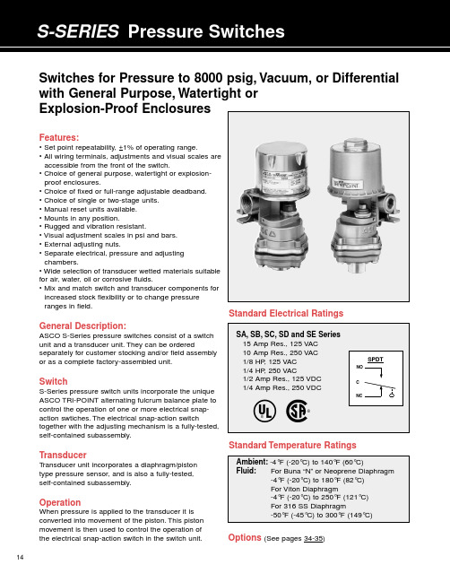
14Features:• Set point repeatability, +1% of operating range.• All wiring terminals, adjustments and visual scales are accessible from the front of the switch.• Choice of general purpose, watertight or explosion-proof enclosures.• Choice of fixed or full-range adjustable deadband.• Choice of single or two-stage units.• Manual reset units available.• Mounts in any position.• Rugged and vibration resistant.• Visual adjustment scales in psi and bars.• External adjusting nuts.• Separate electrical, pressure and adjusting chambers.• Wide selection of transducer wetted materials suitable for air, water, oil or corrosive fluids.• Mix and match switch and transducer components for increased stock flexibility or to change pressure ranges in field.General Description:ASCO S-Series pressure switches consist of a switch unit and a transducer unit.They can be orderedseparately for customer stocking and/or field assembly or as a complete factory-assembled unit.SwitchS-Series pressure switch units incorporate the unique ASCO TRI-POINT alternating fulcrum balance plate to control the operation of one or more electrical snap-action swtiches.The electrical snap-action switchtogether with the adjusting mechanism is a fully-tested,self-contained subassembly.TransducerT ransducer unit incorporates a diaphragm/piston type pressure sensor, and is also a fully-tested, self-contained subassembly.OperationWhen pressure is applied to the transducer it is converted into movement of the piston.This pistonmovement is then used to control the operation of the electrical snap-action switch in the switch unit.Standard Electrical RatingsSwitches for Pressure to 8000 psig, Vacuum, or Differential with General Purpose, Watertight or Explosion-Proof EnclosuresStandard Temperature RatingsOptions (See pages 34-35)EnclosuresASCO TRI-POINT S-Series switches are available in three standard enclosures.All of these enclosed units are made in accordance with NEMA and UL standards. General Purpose–Type 1.These enclosures are designed for indoor use to protect personnel from accidental contact with the equipment.S-Series general purpose switch units consist of a copper-free* aluminum die-cast body with a formed copper-free* aluminum cover;two 3/4”conduit hubs with one plug are provided.Watertight–T ype 4.Watertight and dust-tight enclo-sures are intended for use indoors and outdoors to protect the enclosed equipment against splashing or falling water, windblown dust and water, hose directed water, and severe external condensation.S-Series watertight switch units have a copper-free* aluminum die-cast body and a formed copper-free* aluminum cover with Buna “N”gaskets;two 3/4”conduit hubs with one plug are provided.Explosion-Proof–T ypes 7 and 9.T ype 7 enclosures are intended for use in locations defined by the National Electrical Code as Class I.T ype 9 enclosures are intended for Class II locations.Class I locations are those in which flammable gases are or may be present in the air in sufficient quantities to produce explosive or ignitable mixtures.Class I loca-tions are classified by group letter, which defines partic-ular atmospheres.Division 1 locations are areas where the hazardous concentration exists continuously, inter-mittently or periodically under normal operating condi-tions.Division 2 locations are those where the haz-ardous vapors are present only in case of accidental rupture or breakdown of equipment.ASCO TRI-POINT explosion-proof enclosures with letter B, C or D in the fifth position are listed for Class I, Groups B, C, and D, Division 1.They are also suitable for the less stringent Division 2 environment.Class II locations are those which are hazardous because of the presence of combustible dust.All ASCO TRI-POINT explosion-proof enclosures are listed for Groups E, F, and G locations.The switch body and cover are die-cast copper-free* aluminum with a Buna “N”gasket.T wo 3/4”conduit hubs with one plug are provided.Dimensions (inches)* Less than 0.6% copper.1518the maximum1934H-Series, P-Series and S-Series Snap-Action Switch OptionsOptional snap-action switches to meet specific electrical loads or application conditions are available on most ASCO TRI-POINT switch units. Generally, the construction of a switch unit with optional snap-action switches contains other specific parts and may be ordered only as a factory-built unit. To specify a particular optional construction, add the appropriate suffix to the switch unit action switch (suffix “P ”P-SeriesSwitch OptionsPanel Mount –Open frame P-Series compact switch units areavailable for panel mounting with the switch unit inside and the transducer outside. The panel separates the fluid sensing portion from the electromechanical portion. Five holes for bolts and operating stem must be drilled or punched through the panel.Three constructions are available: add the suffix listed below to the switch unit catalog number for the desired thickness.S-SeriesSwitch OptionsIndustrial Adjusting Nut Covers –Available in clear plastic or metal to prevent tampering with set point adjusting nuts.Clear plastic cover:To order, add suffix “1” to the switch unit catalog number, or order separately as SP01.Metal cover:To order, add suffix “2” to the switch unit catalog number, or order separately as SP02.JIC Construction –A switch unit having the electrical and adjusting nut covers attached to the switch body by a chain. Also designed to Type 13specifications. To order, add suffix “3”to the switch unit catalog number, or order separately as SP03.Terminal Block –Applicable to switch units with one single-poledouble-throw switch. The terminal strip is prewired to the snap-action switch. To order, add suffix “4” to the switch unit catalog number, or order separately as SP04.Factory Sealed –Explosion-proof units may be ordered with a factory seal separating the electrical chamber from the conduit hubs and 24” long #14 AWG 105°C. rated lead wires. To order, change the fourth digit of the “3”35Pressure Transducer OptionsP-Series and S-Series Temperature Transducer OptionsSpecial Wetted Materials –The following diaphragms maybe substituted on transducer body materials of aluminum,brass, polyester and stainless steel. To order, substitute the Oxygen Cleaning –Pressure transducers for oxygen serviceshould be specially cleaned. They are degreased and blacklight inspected, then assembled in a clean area and tested with oil-free air or nitrogen. Use metal body transducer with viton or neoprene diaphragm and add suffix “H ”Pressure Snubbers –A pressure snubber (1/4” NPTF by1/4” NPTM) installed in the transducer pressure connection will dampen the pressure spikes to a value which will not cause damage. It consists of a body with a porous metal disc of stainless steel through which the fluid passes. To order,select a snubber compatible with the fluid. Available by seperate catalog number only (see table below).Process Connection –A female process connection (1/4”NPT) is standard on all pressure transducers. A 1/2” NPT is available as an option on gauge pressure transducers. To order, add suffix “B ”Note: Armored Capillaries –Double braided copper armor isstandard for copper capillary units. Stainless steel spiral interlocked armor is available for stainless steel capillary units. Add suffix “C ” to transducer catalog number.Thermal Well –Use with direct or remote sensors forprotecting sensing bulb. This allows removal of bulb while maintaining a pressure-tight vessel. Available in 1/2” NPT or 3/4”NPT process connection in brass or 316 SS. Dimensions are in accordance with SAMA Std. RC17-9. Standard “U ” dimension (insertion length) is 2-1/2” for direct mount and 6’capillary units and is 4-1/2” for 12’capillary units.Longer Capillaries –Standard copper and stainless steelcapillary units can be furnished in 12’lengths. To order, add suffix “D ” to transducer catalog number. Consult ASCO for longer length capillaries.Union Connector –For use with remote units for mountingof bulb in fluid being controlled. Available in 1/2” NPT and 3/4” NPT process connections in brass or 316 SS.Thermal WellJam nuts provided with thermal wells.11Switch Unit – ASCO uses the term “switch unit ” to describe the electromechanical portion of a pressure or temperature switch. This is used in conjunction with a transducer unit to form a complete pressure or temperature switch.Transducer Unit – ASCO uses the term “transducer unit ” to describe that portion of a pressure or temperature switch to which a pressure or temperature is applied which converts the input signal to another form of energy to operate the switch unit.Two-Stage (Dual)– ASCO uses the term “two stage ” todescribe a pressure or temperature switch which is equivalent to two pressure or temperature switches which are independently adjustable. This switch is equivalent to two fixed deadband switches.Deadbands – The deadband is the difference between the set point and reset point readings. Deadbands are listed in the specification tables at nominal values. They are representative of the deadbands of the units at the middle of the range.The deadband values for the full range adjustable deadband switches and limited adjustable deadband switches indicate the values through which the deadband may be adjusted.Generally, as the set point is adjusted through the operating range, the deadband will vary. Normally, it will becomenarrower as the set point is towards the bottom of the range,and will become wider when the set point is towards the top of the range. The graph shown below indicates representative trends of this type of deadband variation.Temperature switch deadbands are a result of the characteris-tics of the vapor pressure curve as well as other factors.Normally, this results in a deadband which is narrower in the top third of the range than in the bottom third of the range.The values published are nominal and representative of mid-range set points.36Accuracy – The maximum deviation from the set point under specified operating condition (ambient temperature,barometric pressure, etc.).Adjustable Deadband – Refers to the capability of apressure or temperature switch to allow the deadband to be adjusted over a given range. Certain ASCO TRI-POINT switches have an adjustable deadband which can be adjusted over the total operating range of the switch.Adjustable Operating Range – The pressure or tempera-ture range of the switch within which the set point may be adjusted.Differential Pressure – The difference between twopressures. A differential pressure switch senses two pressure sources and can be adjusted to actuate on a desired difference between them.Guage Pressure – The actual reading of a typical pressure guage and is the difference between the pressure within a vessel and the atmospheric pressure surrounding it. It is normally measured in pounds per square inch (psig).Manual Reset – The switch is a semi-automatic device which operates automatically with a signal change in one direction but must be manually reset once the signal returns to its original position.Proof Pressure – A pressure which a device can besubjected to for extended periods of time without changes in its operating characteristics.Rated Overrange Temperature – A temperature which a device can be subjected to for extended periods of time without changes in its operating characteristics.Repeatability – The closeness of agreement among a number of consecutive measurements of the output for the same value of input under the same operating conditions approaching from the same direction. Repeatability isnormally specified as a percentage of the upper limit of the operating range.Example: Operating range 5-100 psig with +1%repeatability; equals +1% of 100 psig or +1 psig.Reset Point – After a pressure or temperature switch has reached its set point and operated the electrical switch, it must return to a point called the reset point before the electrical switch can return to its original position.Set Point – The pressure reading at which the electrical switch element changes contact position (it can be specified either increasing or decreasing).DefinitionsDeadbands1.5 x Catalog Value Catalog Value Half Catalog ValueBottom Mid TopPosition of Set Point in Range37These recommendations are to be used as a guide only, as service life of material is dependent on temperature, concentrations, or catalysts that may be added and other conditions which are beyond our control.Consult ASCO for specific service applications.Note:Items in black circles are standard catalog units.All others available on factory order.P - Indicates preferred construction. S - Indicates satisfactory construction.Transducer Material Code of Two Digits represents process connection material and diaphragm material, respectively; these are the sixth and seventh positions of the pressure transducer catalog number.Process Connection: 6th Position Diaphragm: 7th Position 1 Aluminum 4 316 S.S. 1 Buna “N ” 4 316 S.S.2 Brass 7 Nylon/Brass2 Viton6 Ethylene Propylene 3 303 S.S.3 Neoprene7 FluorosiliconeFluid Compatibility GuideFor high purity applications use stainless steel transducers.Notes:1Oxygen service requires special cleaning, specify suffix “H ”.2For steam service a condensate loop (pigtail) is required.3For pressure transducers for combustion service see pages 20-23.4Material availability refers to standard gauge pressure constructions only.5。
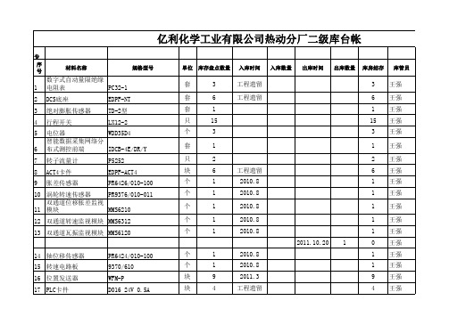
二级库库存台帐1
2 500 5 35 35 35 35 35 35 35 2 4 2 2 4 6 4 4
2 1 2 1
王强 王强 王强 王强 王强 王强 王强 王强 王强 王强 王强 王强 王强 王强 王强 王强 王强 王强 王强 王强 王强 王强
块 CPU Intel Core i7 870X带风扇 块 CoolermasterGX650W
29 LU智能仪表 30 通讯模块 31 双金属带远传温度计 奥玛执行器电路逻辑 32 板 奥玛执行器电路控制 33 板 奥玛执行器电路定位 34 板 S7-200CM可编程序控 35 制器 可编程序控制器(除 36 灰AI卡件)
LU-906MAC4J10012 EDS-305 WSSX-413 0~100℃ 1PCS 2015.909/01-E20 2024.657/01-02 6ES 7231-OHC22-OXA8 CS1W-AD081-U1
化水水位二次表
厦门安东电子有限公司 西门子
日常维护 奥玛执行器检修维护 奥玛执行器检修维护 奥玛执行器检修维护 奥玛执行器检修维护 化水PLC
西安仪表 AUMA AUMA AUMA 西门子 欧姆龙上海有限公司
抽汽快关阀反馈
上海龙井电器有限公司 西门子
日常维护 日常维护 汽机油压保护 除尘操作员站维护 摄像头配件 油角阀配件 日常维护
块 块 块 套 块 块 块 块 米
1 1 1 6 11 2 5 2 2000 2011.11 300 2011.11.25 2011.12.8
1 1 1 2 11 2 5 2 2000 1700 15 5 5 2 2 2 2 1 4 4 10 1
王强 王强 王强 王强 王强 王强 王强 王强 王强 王强 王强 王强 王强 王强 王强 王强 王强 王强 王强 王强 王强 王强
RO反渗透系统调试和正常使用

和浓水调节阀配合使用调整膜管内压力和供水量。开机前应首先将
其打开少许,待泵启动后再慢慢打开,防止瞬间高压对膜造成损害, 而后调整各项指标。
RO系统流程中各个部件名称及作用
8.高压开关
选用韩国3S开关,型号:JC-230。高压开关是保证系统在设定最 大压力值以下运行的保护装置。当原水供水压力高于系统设定值时, 压力开关会自动将高压泵关闭。高压开关可以避免设备超压运行造 成设备的危害,R0系统设定高压开关常规值为15 kg/cm2。
RO系统调试和正常使用
LOGO
RO系统调试和正常使用
•第一部分
RO系统流程
•第二部分:
RO系统的正常使用
RO系统流程
1、RO系统常规流程图
RO系统流程
2、RO系统流程中各个部件名称及作用
3、RO的过滤方式和基本控制
RO系统流程
1、RO系统常规流程图
RO系统流程
RO系统实物对照图
RO系统流程中各个部件名称及作用
比如多介质过滤器、活性炭过滤器、盘滤等都采用全量过滤的方式,
超滤可以采用全量过滤也可以采用错流过率,反渗透就必须采用错流 过率。
RO的过滤方式和基本控制
错流过滤与全量过滤示意图 Depth Filtration
2 Streams Feed
Membrane
Permeate
Crossflow Filtration
清洗水泵及清洗过滤器等。
RO的过滤方式和基本控制
RO的过滤方式 和基本控制
全量过滤与 错流过滤
RO控制实现
RO的过滤方式和基本控制
错流过滤
RO的过滤方式和基本控制
全量过滤
RO控制实现
大金VRV3技术手册
变频风扇
由于该系统为空气热交换系统,因此,风扇使用变频器以 8 级转速运转。
电子膨胀阀(总:EV1)
在加热操作过程中,使用 PI 控制,使空气换热器的出口过 热度保持稳定。
电子膨胀阀(过冷:EV3) 使用 PI 控制,使过冷换热器的出口过热度保持稳定。
电磁阀(热气体:SVP) 用于防止低压瞬时下降。
R6T
R7T
变频压缩机(INV)
变频压缩机使用变频器运转,频率为 26rps 至 105rps;而
标准压缩机 1 (STD 1)
标准压缩机仅采用商用电源运转。变频压缩机与标准压缩 机结合运行时的运行级数如下。 RXYQ10,12P:37 级
变频风扇
由于该系统为空气热交换系统,因此,风扇使用变频器以 9 级转速运转。
电子膨胀阀(总:EV1)
在加热操作过程中,使用 PI 控制,使空气换热器的出口过 热度保持稳定。
电子膨胀阀(过冷:EV3) 使用 PI 控制,使过冷换热器的出口过热度保持稳定。
电磁阀(热气体:SVP) 用于防止低压瞬时下降。
电磁阀(回油:SVO) 用于从储液器向压缩机回油。
四通阀
用于在冷却和加热模式之间切换。
[冷却操作] 控制压缩机容量,对 Te 进行调整以达到目标值 (TeS)。 Te 设定值(在设置模式 2 下进行该设置)
Te 设置
M(正常出厂
L
H
设置)
Te:低压等价饱和温度(℃)
TeS:目标 Te 值 (因 Te 设置、操作频率等的不同而不同)
*在带多台室外机的系统中,根据由压力传感器检测 到的最优先单元的值进行该控制。
制冷剂回路
Si39-505
1.2 RXYQ8P
Honeywell压力开关产品介绍及特点说明书
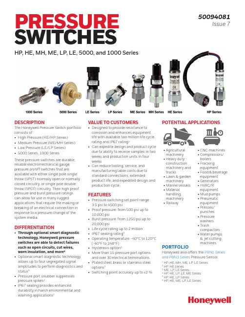
DESCRIPTIONThe Honeywell Pressure Switch portfolio consists of:• High Pressure (HE/HP Series)• Medium Pressure (ME/MH Series)• Low Pressure (LE/LP Series)• 5000 Series, 1000 SeriesThese pressure switches are durable, reliable electromechanical gauge pressure on/off switches that are available with either single pole single throw (SPST) normally open or normally closed circuitry, or single pole double throw (SPDT) circuitry. Their high proof pressure and burst pressure ratingscan allow for use in many rugged applications that require the making or breaking of an electrical connection in response to a pressure change of the system media.DIFFERENTIATION• Through optional smart diagnostic technology, Honeywell pressure switches are able to detect failures such as open circuits, cut wires, worn insulation, and more6• Optional smart diagnostic technology allows up to four segregated signal amplitudes to perform diagnostics and status6• Pressure port snubber suppresses pressure spikes2• IP67 sealing provides enhanced durability in harsh environmental and washing applications1POTENTIAL APPLICATIONS • Agriculturalmachinery• Heavy dutyconstructionmachinery andtrucks• Lawn & gardenmachinery• Marine vessels• Materialhandlingmachinery• Railway• CNC machines• Compressors/boilers• Frackingequipment• Food & beverageequipment• Generators• HVAC/Requipment• Mud pumps• Pneumaticequipment• Presses/punches• Pressurewashers• Trashcompactors• Water pumps& jet cuttingmachines PORTFOLIOHoneywell also offers the PBN1 Series and PBN3 Series Pressure Sensor.1 HP, HE, MH, ME, LP, LE Series2 HP, HE Series3 ME, LP, LE Series4 HP, HE, LP, LE, ME Series5 HP, HE, LP Series6 HP, HE, ME, LP, LE SeriesPRESSURE SWITCHES HP, HE, MH, ME, LP, LE, 5000, and 1000 Series 50094081Issue 7VALUE TO CUSTOMERS• Designed to provide resistance to corrosion and enhances equipment life with available two million life cycle rating and IP67 rating1• Can expedite design and product cycle due to ability to receive samples in two weeks and production units in four weeks• Can reduce tooling, service, and manufacturing labor costs due to standard connections, extended product life, and expedited design and production cycleFEATURES• Pressure switching set point range: 3.5 psi to 4500 psi• Proof pressure: from 500 psi up to 10,000 psi• Burst pressure: from 1250 psi up to 20,000 psi• Life cycle rating up to 2 million• IP67 sealing rating4• Operating temperature: -40°C to 120°C [-40°F to 248°F]• Hysteresis option5• More than 15 pressure port options and over 30 electrical terminations • Plated steel, brass or stainless steel options3• Switching point accuracy up to ±2 %8Port Style C: Switches less than 975 psi will use Base Style B; switches greater than 975 psi will use Base Style A.Port Styles F and G: Switches less than 350 psi will use Base Style B; switches greater than 350 psi will use Base Style A. Port Styles A, B, E, M, P, T, and Y will use Base Style B.Switches less than 150 psi will only use Base Style B.2 /ast2Operating pressure: Maximum normal system operating pressure3Proof pressure: Maximum pressure that the switch can handle while it maintains set point accuracy. Intermittent spikes to this level are acceptable. 4Burst pressure: Point of complete switch failure5SPST: Single pole, single throw. SPDT: Single pole, double throw. NO: Normally open. NC: Normally closed. 6Field adjustability only available with AA, BA, CA, and DA (SPST only) terminations.7IP00 for AA and BA terminations.Honeywell Advanced Sensing Technologies 3*These connectors are designed for dual circuit (SPDT) by default. They can be used for single-circuit applications (SPNC/SPNO) by making suit-able connections. Refer to wiring diagram.4 /astHoneywell Advanced Sensing Technologies 5DIMENSIONS - HIGH PRESSURE: HP SERIES (BASE STYLE A), HE SERIESBase Style A key specifications • Life: 2 million (HP), 1 million (HE); Burst pressure: 20,000 psiFigure 1. AMP Superseal 1.5(top view)Female Connector Part Number (included): C-282105Male Mating Connector (customer provided): C-282087IP Rating: IP67(top view)Female Connector Part Number (included): DT04-3P Male Mating Connector (customer provided): DT06-3S IP Rating: IP67(top view)27 mm [1.063] hex A/F(top view)IP Rating: IP676 /astDIMENSIONS - HIGH PRESSURE: HP SERIES (BASE STYLE B)Base Style B key specifications • Life: 1 million; Burst pressure: 9,000 psi1Port Style C: Switches less than 975 psi will use Base Style B; switches greater than 975 psi will use Base Style A.2Port Styles F and G: Switches less than 350 psi will use Base Style B; switches greater than 350 psi will use Base Style A. Switches less than 150 psi will use only Base Style B.Figure 6. HP Series Base Style Bfor all base ports.Honeywell Advanced Sensing Technologies 7DIMENSIONS - MEDIUM PRESSURE: MH SERIESFigure 13. MH Series Pressure Port DimensionsFigure 8. AMP Superseal 1.5Figure 12. Screw terminal8 /astDIMENSIONS - MEDIUM PRESSURE: ME SERIESFigure 20. ME Series Pressure Port DimensionsMale mating connector (customer provided): C-282087IP rating: IP67Female connector part number (included): DT04-3P Male mating connector (customer provided): DT06-3S IP rating:IP67Figure 17. Wire outMale mating connector (customer provided): DT06-2S IP rating:IP67Honeywell Advanced Sensing Technologies 9DIMENSIONS - LOW PRESSURE: LP SERIES, LE SERIESFigure 24. Wire outFigure 27. LP/LE Series Pressure Port Dimensions10 /astDIMENSIONS - 1000 SERIES, 5000 SERIESFigure 28. 1000 Series Dimensions[0.39 in]Figure 29. 5000 Series DimensionsTHoneywell Advanced Sensing Technologies 11NOMENCLATURE: HIGH PRESSUREHPSeriesSet PointRPressure UnitPHP Series HE Series (100 psi to 4500 psi),High Pressure SwitchFPort TypePressure Set Point05500NOutputBaseSPActuation/ApplicationOptionsAAAConnector TypePackaging Options01They can be used for single-circuit applications (SPNC/SPNO) by making suitable connections. Refer to wiring diagram.For example, HPR05500PFNSPAAA01 defines a high pressure switch, rising factory set, non-adjustable set point, 550 psi set point, psig, sealed gage pressure unit, M14 x 1.5 port type, SPST-NO silver contacts output, cold-rolled steel base, glycol-based fluid (EPDM) actuation/application, spade terminal connectors, standard switch, individually boxed units.12 /astNOMENCLATURE: MEDIUM PRESSURE, HIGH BURSTMHSeriesSet PointRPressure UnitPMedium PressureSwitchAPort TypePressure Set Point01500POutputBaseNMActuation/ApplicationOptionsAAAConnector TypeThey can be used for single-circuit applications (SPNC/SPNO) by making suitable connections. Refer to wiring diagram.Packaging Options01For example, MHR01500PFPNMAAA01 defines a medium pressure, high burst switch, rising factory set, non-adjustable set point, 150 psi set point, psig, sealed gage pressure unit, 1/4-18 NPT port type, SPST-NO contacts output, plated steel base, LTNB diaphragm, and spade terminal connectors.Honeywell Advanced Sensing Technologies 13NOMENCLATURE: MEDIUM PRESSUREMESeriesSet PointRPressure UnitPMedium PressureSwitchFPort TypePressure Set Point01500POutputBaseVKActuation/ApplicationOptionsAPackaging Options01AAConnector TypeThey can be used for single-circuit applications (SPNC/SPNO) by making suitable connections. Refer to wiring diagram.For example, MER01500PFPVKAAA01 defines a medium pressure switch, rising factory set, non-adjustable set point, 55 psi set point, psig, sealed gage pressure unit, M14 x 1.5 port type, SPST-NO gold-plated contacts output, stainless steel base, Kapton ® diaphragm (Teflon ® coated), Nitrile O-ring actuation/application, spade terminal connectors, standard switch, individually boxed units.14 /astNOMENCLATURE: LOW PRESSURELPSeriesSet PointRPressure UnitPLowPressureSwitchFPort TypePressure Set Point00550POutputBaseVKActuation/ApplicationOptionsAPackaging Options01AAConnector TypeThey can be used for single-circuit applications (SPNC/SPNO) by making suitable connections. Refer to wiring diagram.**For electrical termination with SPST option, only SPNOconfiguration is available. SPNC configuration cannot be provided.For example, LPR00550PFPVKAAA01 defines a low pressure switch, rising factory set, non-adjustable set point, 55 psi set point, psig, sealed gage pressure unit, M14 x 1.5 port type, SPST-NO gold-plated contacts output, stainless steel base, Kapton ® diaphragm (Teflon ® coated), Nitrile O-ring actuation/application, spade terminal connectors, standard switch, individually boxed units.® DuPont™, Teflon ®, Tefzel ®, and Kapton ® are trademarks or reg-istered trademarks of E.I. du Pont de Nemours and Company50094081-7-EN | 7 | 04/21© 2021 Honeywell International Inc.WARRANTY/REMEDYHoneywell warrants goods of its manu-facture as being free of defective materi-als and faulty workmanship during the applicable warranty period. Honeywell’s standard product warranty applies un-less agreed to otherwise by Honeywell in writing; please refer to your order ac-knowledgment or consult your local sales office for specific warranty details. If war-ranted goods are returned to Honeywell during the period of coverage, Honeywell will repair or replace, at its option, without charge those items that Honeywell, in its sole discretion, finds defective. The foregoing is buyer’s sole remedy and is in lieu of all other warranties, expressed or implied, including those of merchantability and fitness for a particular purpose. In no event shall Honeywell be liable for consequential, special, or indirect damages.While Honeywell may provide applica-tion assistance personally, through our literature and the Honeywell web site, it is buyer’s sole responsibility to determine the suitability of the product in the ap-plication.Specifications may change without notice. The information we supply isbelieved to be accurate and reliable as of this writing. However, Honeywell assumes no responsibility for its use.m WARNINGPERSONAL INJURYDO NOT USE these products as safety or emergency stop devices or in any other application where failure of the product could result in personal injury.Failure to comply with theseinstructions could result in death or serious injury.m WARNINGMISUSE OFDOCUMENTATION•The information presented in this product sheet is for reference only. Do not use this document as a product installation guide.•Complete installation, operation, and maintenance information is provided in the instructions supplied with each product.Failure to comply with theseinstructions could result in death or serious injury.HoneywellAdvanced Sensing Technologies 830 East Arapaho Road Richardson, TX /astFOR MORE INFORMATIONHoneywell Advanced SensingTechnologies services its customers through a worldwide network of sales offices and distributors. For application assistance, current specifications, pricing, or the nearest AuthorizedDistributor, visit /ast or call:USA/Canada +302 613 4491Latin America +1 305 805 8188Europe +44 1344 238258Japan +81 (0) 3-6730-7152Singapore +65 6355 2828Greater China+86 4006396841。