罗塞塔安装指南
罗塞塔安装教程
加了。如下图
10 (这一步不操作也不影响的)建议在 C:\windows\system32\drivers\etc\下修改文件,用记事本打开修改, 添加如下文字,添加到最后面,添加后保存 !!如果无法保存的话,吧文件 hosts 剪切到桌面修改好了再拷 贝过来 127.0.0.1 127.0.0.1 127.0.0.1 127.0.0.1 这样便彻底断根,不会有后遗症了!
7 添加完成,可以点击继续,提示更新的话还是点退出。
注意:软件使用过程中,我们不更新,不激活,不升级, 我们这里选择取消更新。
点击“稍后提醒我”。
点击“从不注册”。 8 重新打开软件,自己创建个角色。创建好后点击右下角的继续,创建完成就可以
使用了!! 9 继续添加语言包的话,点软件右上方的添加语言。用虚拟光驱加载之后就可以添
解决办法: 目前推荐使用微软的反病毒软件:Security Essentials(免费)。 如果还有其他反病毒软件没有导致罗赛塔石碑出错,请告知,谢谢。 8. 在线更新 问题描述: 是否应该在线更新?
解决办法: 建议在线更新语言级别。 如果你对自动更新不了解,请不要做任何更新,因为这不是必须的,且作用不大。 9. 学习进度备份 问题描述: 如何备份学习进度?
罗塞塔 4.1.15 详细安装图文教程
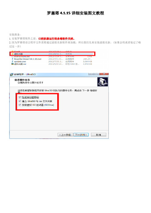
安装准备: 1.安装罗赛塔软件之前,⑴把机器运行的杀毒软件关掉。 2.因为罗赛塔语言程序文件需要通过虚拟光驱软件来加载,所以我们先来安装虚拟光驱。(如果会用或者装过了略 过这一步)
虚拟光驱安装好后现在开始安装软件:
1. 先安装 Rosetta Stone V4.1.10.exe 安,双击 Rosetta Stone V4.1.10.exe 安装文件。进 行安装。默认安装到 C 盘
arena14安装步骤
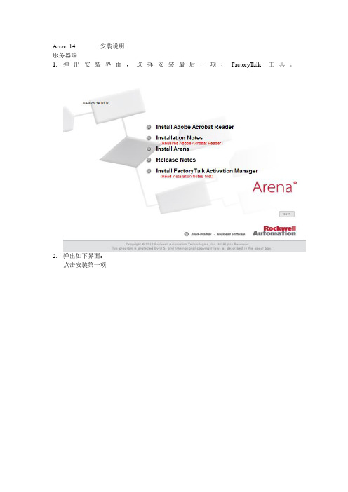
Arena 14 安装说明服务器端1.弹出安装界面,选择安装最后一项,FactoryTalk工具。
2.弹出如下界面:点击安装第一项3.之后的所有步骤均点击下一步即可。
4.安装完成之后,打开所有程序,找到如下图所示:点击启动5.启动之后弹出如下界面:点击中间部分的Get New Activations,从而获得新的授权。
需要注意的是获得新授权是在第一次从国外服务器下载授权时使用的。
6.7.点击之后弹出如下界面:点击右下角的choose Destination8.出现如下界面:点击Enter activation9.出现如下界面:其中Serial # 和Product Key 为红色信封中所显示的号码,Host ID 为绑定硬件的信息,点击后面的小方块,弹出如下图通常情况下绑定系统硬盘号。
都输入完成之后点击上图右下角的Validate Activation进行验证,然后选择下载的数量完成授权下载。
客户端1.客户端也需要安装FactoryTalk工具,安装过程同服务器端的2、3、4步骤一致2.当进入到如下界面时:选择Find Available按键,弹出如下界面:在此界面中点击右上角蓝色的字母,Update Path。
会弹出如下界面点击Add Server添加服务器地址。
在新增加出来的一行中,点击右边的小方块:在弹出的界面中选择服务器的主机名称即可,选中之后将新添加的Server勾选上,点击右下角的Save。
接下来点击下图中的Refresh:如果能刷新出来如图中的各种组件,就代表链接服务器成功。
成功后在安装Arena的主程序即可。
第三个选项,安装过程全部下一步。
完成安装。
3.如果一些情况下,客户机需要脱离网络环境来使用,arena也提供了如下功能。
在下面的界面之中:点击Borrow Activation弹出如下界面:如果刚刚设置成功会有上图的界面,将Product的方块勾选上。
点击Set borrow term,点击右下角的borrow,完成借用。
rosetta罗塞塔安装使用必读
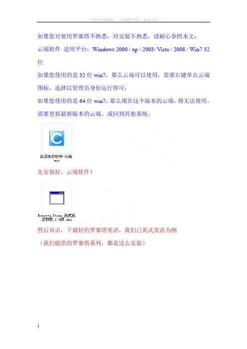
如果您对使用罗塞塔不熟悉,对安装不熟悉,请耐心参照本文:云端软件适用平台:Windows 2000 / xp / 2003/ Vista / 2008 / Win7 32位如果您使用的是32位win7,那么云端可以使用,需要右键单击云端图标,选择以管理员身份运行即可;如果您使用的是64位win7,那么现在这个版本的云端,将无法使用。
需要更新最新版本的云端。
或回到其他系统。
先安装好,云端软件!然后双击,下载好的罗塞塔英语,我们已英式英语为例(我们提供的罗塞塔系列,都是这么安装)双击后,会出现以上画面,先点击更改解压位置,看看解压的硬盘,剩余空间是否足够点击后,会出现以下画面,这图里的软件解压位置,意思就是,罗塞塔英语将会被安装在D盘CloudCache文件夹,15.11G是可用剩余空间/54.99G是硬盘总大小,一般最好要6G剩余空间以上。
如果剩余空间不够,罗塞塔将会中断安装,那就点击那个向下的箭头,选择其他盘安装。
确定剩余空间足够,点击开始解压等到解压完成100%成功然后双击打开云端软件,在我的软件内,找到解压好的罗塞塔英语(RosettaStoneVersion3)双击就能使用.如果在我的软件内没有找到,解压好的罗塞塔,请去安装盘D盘CloudCache文件夹,里面有个这样的文件,双击,选择导入然后等待导入成功,再去云端内-我的软件-肯定会有导入后的罗塞塔系列了。
注意:如果你已经在云端内,安装了2~3个软件,一下子无法分出,哪个是新安装的软件,请找到这个.lva文件,因为它的大小跟新安装的软件,大小是差不多的,所以你可以很容易的指导是哪个了。
比如罗塞塔英式英语下载好的软件是 1.2G,那它的.Lva文件,是1.26G,基本是差不多大的,依此类推。
技术支持QQ:744142802 旺旺:云的彼端sunny罗塞塔使用介绍:罗塞塔美式英语1~5级,英式英语1~3级,区别是,发音不同,内容一样的,但美式英语内容更多,以美语为例:1~2级是基础入门。
罗塞达石碑安装
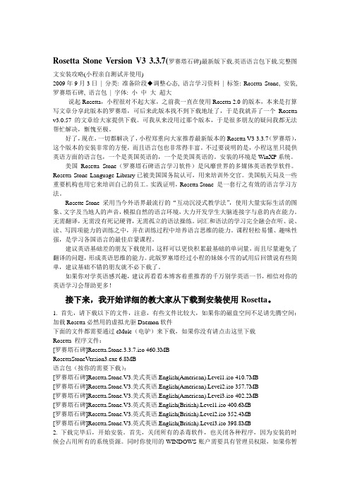
Rosetta Stone Version V3 3.3.7(罗赛塔石碑)最新版下载.英语语言包下载.完整图文安装攻略(小程亲自测试并使用)2009年9月3日| 分类: 准备阶段◆调整心态, 语言学习资料| 标签: Rosetta Stone, 安装, 罗赛塔石碑, 语言包| 字体: 小中大超大说起Rosetta,小程很对不起大家,之前我一直在使用Rosetta 2.0的版本,本来是打算写文章分享此版本的罗赛塔,可后来此版本找不到下载地址了,于是我就弄了一个Rosetta v3.0.57的文章给大家提供下载。
可我从来没用过那个版本,于是很多朋友的疑问我都无法帮忙解决,惭愧至极。
好了,现在,一切都解决了,小程郑重向大家推荐最新版本的Rosetta V3 3.3.7(罗赛塔),这个版本的安装非常的方便,而且语言包也非常得丰富。
不过要说明的是,小程这里只提供英语方面的语言包,一个是英国英语的,一个是美国英语的。
安装的环境是WinXP系统。
美国Rosetta Stone(罗赛塔石碑语言学习软件)是风靡世界的多媒体英语教学软件。
Rosetta Stone Language Library已被美国国务院认可,用来培训外交官。
美国航天局及一些重要机构也用它来培训自己的员工。
实践证明,Rosetta Stone 是一套行之有效的语言学习方法。
Rosette Stone 采用当今外语界最流行的“互动沉浸式教学法”,使用大量实际生活的图象、文字及当地人的声音,模拟自然的语言环境,大力开发学生大脑连接字与意的内在能力。
无需翻译,无需没有死记硬背,无需孤立的语法操练。
词汇和语法的学习完全融会在听、说、读、写四项能力的训练之中,并在训练过程中培养语言思维的能力。
课程轻松易懂、趣味性强,是学习各国语言的最佳启蒙课程。
建议英语基础差的朋友下载使用,这样可以更快积累最基础的单词量,而且尽量避免了翻译的问题,形成英语思维的能力。
罗塞塔4.1.15详细安装图文教程
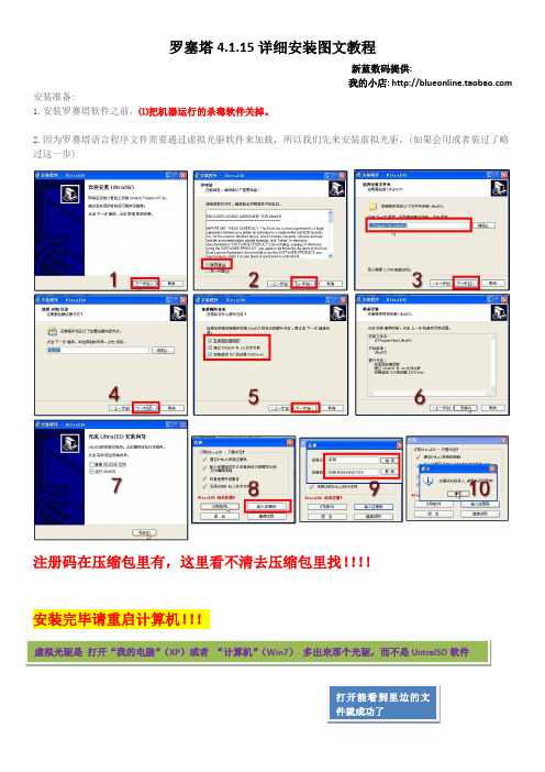
罗塞塔4.1.15详细安装图文教程新蓝数码提供:我的小店: 安装准备:1.安装罗赛塔软件之前,⑴把机器运行的杀毒软件关掉。
2.因为罗赛塔语言程序文件需要通过虚拟光驱软件来加载,所以我们先来安装虚拟光驱。
(如果会用或者装过了略过这一步)注册码在压缩包里有,这里看不清去压缩包里找!!!!安装完毕请重启计算机!!!虚拟光驱是打开“我的电脑”(XP)或者“计算机”(Win7)多出来那个光驱,而不是UntraISO软件打开能看到里边的文下边加载语言包:首先找到你下载好的语言包文件如美式英语等级1:双击在UntraISO软件里打开!在弹出的对话框里选择“加载”,出现“已加载”状态,就OK了。
可以继续安装罗塞塔软件了!OK,前边做好之后就开始安装罗塞塔软件了!!1.接下来,我们来安装罗赛塔石碑的程序文件,打开软件文件夹(你下载的程序压缩包解压出来的文件夹,记得要解压,不要在压缩软件里安装),找到Rosetta Stone V4.1.10.exe安装文件,双击Rosetta Stone V4.1.10.exe安装文件。
2.然后我们根据提示来操作即可。
选择中文(也有其它7种语言可供选择),单击确定。
3.一边的比较简单,不一一介绍了,到选择安装目录,如果C盘空间够用,那么默认安装到C盘即可。
(4.1.15版只能安装在C盘,如果C盘没地方联系掌柜索取3.47版程序,3.47版可以选择安装路径)4.直接装完,不要启动程序,如下图5.运行压缩包里的离线升级包update.exe升级到4.1.15,但是注意提示新版本4.5.5时一定不要更新!!破解(重要):将Crack文件夹下(注意是crack文件夹里的所有文件,不是crack本身)所有文件复制至C:\Program Files\Rosetta Stone\Rosetta Stone TOTALe并覆盖(提示你是否覆盖,点确定就成功了)针对64位系统:路径是C:\Program Files (x86)\Rosetta Stone\Rosetta Stone TOTALe破解完毕,打开软件,遇到下边的界面请填好信息创建一个学习者,(创建下去会出现错误,返回即可,其实已经创建好了。
Rosemount Eagle Eye 快速安装指南说明书
00825-0100-4833, Rev AAJanuary 2004Rosemount Eagle Eye Rosemount Eagle Eye¢00825-0100-4833+¤© 2004 Rosemount Inc. All rights reserved. All marks are the property of their owners.Rosemount Inc.8200 Market Boulevard Chanhassen, MN USA 55317 T (US) (800) 999-9307T (Intnl) (952) 906-8888F (952) 949-7001Emerson Process Management GmbH & Co. OHGArgelsrieder Feld 382234 WesslingGermanyT 49 (8153) 9390F49 (8153) 939172Emerson Process Management Asia Pacific Private Limited1 Pandan CrescentSingapore 128461T (65) 6777 8211F (65) 6777 0947/65 6777 0743Beijing Rosemount Far East Instrument Co., Limited No. 6 North Street,Hepingli, Dong Cheng District Beijing 100013, ChinaT (86) (10) 6428 2233F (86) (10) 6422 8586This installation guide provides basic guidelines for Rosemount Eagle Eye Fire Pump. It does not provide instructions for configuration, diagnostics, maintenance, service, troubleshooting, Explosion-proof, Flame-Proof, or instrinsically safe (I.S.) installations. Refer to the Rosemount Eagle Eye Series Product Data Sheet (document number 00813-0100-4830) or the Eagle Eye QIG (document number 00825-0100-4833) for more information. These documents are also available electronically on . Process leaks may cause harm or result in death. To avoid process leaks, only use gaskets designed to seal with the corresponding flange and o-rings to seal process connections. Flowing medium may cause the 485 Annubar assembly to become hot and could result in burns.E XPLODED V IEWFront View0000-901B , 901CSide View10000-901D , 901AS TEP 1: L OCATION AND O RIENTATION OrientationHorizontalFor proper venting and draining, the sensor should be located in the upper half of the pipe for air and gas applications. For liquid applications, the sensor should be located in the bottom half of the pipe.Figure 1. GasFigure 2. Liquid 2 1 -4 9 0 0 0 0 -9 0 2 B0 0 0 -9 0 2 CS TEP 1 CONTINUED...VerticalThe sensor can be installed in any position around the circumference of the pipe provided the vents are positioned properly for bleeding or venting. Optimal results for liquid are obtained when the flow is up. The preferred orientation for air or gas is when the flow is down, but upwards flow is acceptable.Figure 3. LiquidFigure 4. Gas 2 1 -4 9 0 0 0 0 -9 0 3 B-4 9 0 0 0 0 -9 0 3 BS TEP 1 CONTINUED...Permanent MetersInstall the meter with the dial face in a level horizontal position. This can easily be check with a level. Meter must be installed within ±30° from the vertical position.Figure 5. HorizontalFigure 6. VerticalNOTE 2 1 -4 9 0 0 0 0 -9 0 7 FS TEP 1 CONTINUED ...Portable MetersPortable meters must be used with the dial face in a vertical position.NOTEUse in any other position requires recalibration.Figure 7. Portable Meter Case21-490000-908A , 908B , 908C , 908DDimensions are in inches (millimeters)S TEP 2: M OUNTINGPipeThe Eagle Eye can be mounted on any 1/2 to 2-in. (10 to 50 mm) vertical or horizontal pipe.NOTEA wood spacer of 2 x 4 x 3/4-in. (50 x 100 x 20 mm) is required for mounting on pipe 1/2 to 1-in. (10 to 25 mm). Screw holes are provided in the pipe mounting bracket to attaching the spacer1.Insert the two “U” bolts through the large holes in the meterbracket.2.Torque the flange bolts to only 50 in/lb (56 kg/cm).Figure 8. Pipe Mounting21-490000-904ADimensions are in inches (millimeters)S TEP 2 CONTINUED...WallThe Eagle Eye can be wall mounted by removing the mounting bracket from the meter. This permits access to the to 3/16-in. (5 mm) holes in the bracketNOTEOnly remove the two flange bolts attaching the bracket to the meter bodyFigure 9. Wall MountS TEP 2 CONTINUED ...Flush PanelThe meter can be flush mounted in panels 1/16 to 1/4-in. (2 to 6 mm) thick. The exact panel cutout size is 43/4-in. (12 mm) high by 67/16-in. (16.5 mm) wide. Clips are furnished for flush panel mounting.Figure 10. Flush Panel Mount21-490000-906BDimensions are in inches (millimeters)S TEP 3: O PERATIONEqualize the system1.Mount the Eagle Eye Indicator in the vertical position, but do notconnect it to the Annubar.2.Remove the cover access plate by unscrewing the two front coverscrews and gently prying the cover from the right side. (This give access to the equalizer valve)The equalizer valve provides a path between the high- and low- pressure sides of the meter.•Clockwise rotation of the screw closes the valve•Counter-clockwise rotation of the screw opens the valve •Full closed to full open required 1 ½ to 2 turns The equalizer valve is used during the bleeding process, (see “Bleeding or Draining the System”)NOTEPortable meters come with an external equalizer knob (standard).Figure 11. Equalizer ValveCover Access Plate21-490000-909AS TEP 3 CONTINUED...Instrument ConnectionTo the Rosemount 485 Annubar1.Close all Annubar valves.2.Connect the meter tubing to the Annubar.To the Rosemount Eagle Eye1.Close all system valves.2.Insure that all connections are installed correctly.3.Secure the tubing to the meter.e an open-end wrench to hold the meter fittings from rotatingwhile making the connections.Figure 12. ConnectionCAUTIONBe sure to connect the HI-pressure side of the Eagle Eye meter to the HI-pressure side of the Annubar. The HI-pressure side is clearly marked on the Annubar and the Eagle Eye Indicator.S TEP 3 CONTINUED...Bleeding or Draining the SystemAfter all connections are installed and secured, the system should be bled of all air. In air applications, any water or condensate must be drained from the connecting tubing and meter before taking readings. In water applications, all air in the connecting lines and meter must be bled with cool water.1.Install plastic drain tubing onto the bleed valves and run tubing to adrain.2.Open the equalizer valve.3.Open both bleed valves one turn-counter clockwise.4.Open the Annubar LO-pressure valve slowly and just enough tosend a slow, but constant stream of water through the Eagle Eye Indicator.5.Similarly open the Annubar HI pressure valve.6.When the liquid exiting the bleed valve is free of air, close theLO-pressure bleed valve first. Close the HI-pressure bleed valve last.7.Slowly close the equalizer valve.8.Replace the access plate.NOTEThe pointer may register above zero even though the equalizer is open. This indicates the pressure drop across the equalizer.The meter must be bled after each system shutdown.S TEP 4: C ALIBRATIONThe Eagle Eye is calibrated at the factory and should not need to be recalibrated in the field. The full scale calibration point is shown on the backside of the meter. (See the slot opposite “Scale/Reading” on the black and silver tag.)S TEP 5: R EMOVAL F ROM S ERVICE (IF NEEDED)1.Shut down the system valves at the Annubar.2.Open the equalizer by turning the equalizer valve counterclockwise3.Disconnect all the tubing if necessaryCAUTIONIf the Eagle Eye is going to be subject to freezing temperatures, all water must be drained or damage will occurTo prevent injury, when the Annubar sensor is removed from the pipe, eliminate any pipeline pressure and drain the pipeline before loosening the Pak-Lok compression fitting.A PPROVALRosemount 415 Fire Pump approved by Factory Mutual。
Blue Ridge Sauna 安装指南和使用手册说明书

Blue Ridge Sauna Installation & Owner’s ManualRevised December, 2012CHECK YOUR BOXESBe sure to immediately check your boxes against your shipping list and bill of lading. Examine for any damage and and notify Almost Heaven Saunas if there needs to be a repair or replacement of damaged or missing materials.ELECTRICAL REQUIREMENTSAll electrical wiring must be performed by A QUALIFIED LICENSED ELECTRICIAN. Because of the heat involved in the sauna, it is required that you use copper wire with 90ºC insulation. Do not use aluminum wire to make the connection. Consult with an electrician so you can determine the requirements for your particular situation. All wiring must conform to all national, state and local codes and regulations and according to the instructions provided with the heater.LOCATING THE SAUNAYour Blue Ridge Sauna is designed for indoor use. Be sure your sauna is installed on a floor that is firm and flat. In-stalling on carpet is not advised due to both the water that will be used in the sauna as well as the difficulty in assembly on a soft surface. A concrete, tiled or vinyl surface are recommended as ideal surfaces for installation.ASSEMBLYYou should use two people for the assembly of the Blue Ridge Sauna. The wall and roof sections are large and need two people to lift and hold in place during assembly.BASIC TOOLSYou should have the following tools:∙ Cordless drill for driving screws∙ Stepladder or stool∙ Rubber Mallet∙ Claw hammer∙ Screwdrivers (Phillips and Flathead)∙ Framing Square∙ Utility knife∙ Level21. Locate the 4 WALL SUPPORT RAILSThe 4 rails are all identical and will be used to cre-ate the wall support. The rails will support theweight of the sauna but will not be attached to thefloor or assembled sauna walls.NOTE: Be sure your surface is flat before youbegin assembly.Wall Support Rails2. Connect the WALL SUPPORT RAILSConnect the corners using a 2” screw through eachof the 4 pre-drilled holes on the inside of the railgroove.NOTE: Be sure that the rails are square and leveland that the screw head does not protrude into thegroove.Connect Wall Support Rails3. Position completed WALL SUPPORTPlace the completed wall support into position.You will need at least 2’ around each side of thesauna to comfortably complete the assembly.NOTE: Once finished it is possible but not easy toslide the sauna closer to a wall due to the weightof the finished sauna room.Completed Wall Support4. Position WALL SECTION APosition Wall Section A on the left rear side of thesauna according to the guide on ILLUSTRATION1 on following page.NOTE: Wall A should only go as far back in thegroove as shown so that the back wall section Bcan overlap the edge of wall A.Position Wall Section A34 5. Position WALL SECTION B Position Wall Section B on the left rear of the sau-na according to ILLUSTRATION 1.NOTE: Wall Section B will overlap Wall A.Position Wall Section B6. Attach Wall Section B to Wall Section AUsing 2” screws, connect Wall Section B to WallSection A using the pre -drilled holes.NOTE: Be sure the wall edges and top edgesalign evenly.Attach Wall Sections A and BILLUSTRATION 1 The 8 wall sections, A– H, will be positioned in the grooves of the completed wall support section as shown.AB CD E FG H Completed Wall Support7. Position WALL SECTION CPosition Wall Section C on the right rear side ofthe sauna according to the guide on ILLUSTRA-TION 1.NOTE: Wall Section C will attach to Wall Sec-tion B by way of the tongue and groove profile butwill not be fastened with screws.Position Wall Section C8. Position WALL SECTION DPosition Wall Section D on the right rear side ofthe sauna according to the guide on ILLUSTRA-TION 1. Using 2” screws and pre-drilled holes,fasten Wall Section C to Wall Section D.NOTE: As with step 6, be sure the wall edges andtop edges align evenly.Position Wall Section D9. Position WALL SECTION EPosition Wall Section E on the front right side ofthe sauna according to the guide on ILLUSTRA-TION 1.NOTE: Wall Section E will attach to Wall SectionD by way of the tongue and groove profile but willnot be fastened with screws.Position Wall Section E10. Position WALL SECTION FPosition Wall Section F on the right front of thesauna according to the guide on ILLUSTRATION1. Using 2” screws and pre-drilled holes, fastenWall Section F to Wall Section E.NOTE: As with step 6, be sure the wall edges andtop edges align evenly.Position Wall Section F56 Install filler strip to Wall Section F 12. Position WALL SECTION G Position Wall Section G on the left front side of the sauna according to the guide on ILLUSTRA-TION 1. NOTE: Wall Section G will not attach to Wall Section A. Position Wall Section G13. Position WALL SECTION H Position Wall Section H on the front left side of the sauna according to the guide on ILLUSTRA-TION 1. Using 2” screws and pre -drilled holes, fasten Wall Section H to Wall Section G. NOTE: Wall Section H will not attach to the filler strip previously attached to Wall Section F. Position Wall Section H14. Attach WALL CONNECTOR Find the pre -drilled wall connector. Place the wall connector on the top of the front wall edge, bridging walls H, the filler strip, and wall F. Screw it into place with 2” screws.Attach wall connector 11. Install FILLER STRIP Screw the filler strip to Wall Section F to fill the gap between Wall Sections F and H. Optional trim pieces will later be installed over this joint. NOTE: Due to the inherent variations in lumber dimensions, this gap may not be completely filled by the filler piece. This will be addressed later. H15. Build ROOF SUPPORTAssemble 4 roof support rails in the same way youassembled the wall support rails in step 2.NOTE: Be sure that the rails are square and leveland that the screw head does not protrude into thegroove.Completed Roof Support16. Attach ROOF SUPPORT over wallsPosition the completed Roof Support over the wallsections. Once in place on all 4 sides, use 2”screws to attach Roof Support to wall sections.NOTE: Tap the Roof Support firmly in placewith a rubber mallet so wall sections are fully in-serted into the groove before screwing into place.Attach Roof Support over walls17. Position ROOF SECTIONSPlace two Roof Sections on top of Roof Support,nesting the tongue of one section into the grooveof the other. Measure around perimeter before fas-tening to be sure distance from edge is equal.NOTE: Finished side of Roof Sections are to facethe interior of the sauna.Position Roof Sections18. Fasten ROOF SECTIONSUsing 2-1/2” screws, fasten Roof Sections to RoofSupport using pre-drilled holes.NOTE: Be sure to keep even distance from edgeof Roof Section edges and Roof Support edgesaround perimeter of sauna as measured in step 17. Fasten Roof Sections to Roof Support719. Attach ROOF TRIMFind the package of 4 Roof Trim pieces and attachto the raw edge of the Roof Sections with 1-1/2”screws or finish nails.NOTE: The trim pieces are not pre-drilled. Youmay install using screws or finish nails, whicheverstyle you prefer.Attach Roof Trim pieces20. Attach EDGE TRIM - Optional*You can cover the corners of the sauna with EdgeTrim. There are 4 pieces: 4-narrow and 4-wide.Attach with 1-1/2” screws or finish nails, usingone narrow and one wide piece for each corner.Attach the narrow piece first and then overlap withthe wide piece.Attach Edge Trim: OPTIONAL21. Attach WALL TRIM - Optional*There are 6 pieces of wall trim. These can be usedto cover the interior and exterior wall joints be-tween Wall Sections D and E, Wall Sections Hand F, and Wall Sections A and G. Attach with 1-1/2” screws or finish nails.Attach Wall Trim* The use of the Edge Trim and Wall Trim is optional and will not adversely affect the structure or performance of the sauna if not used. Some people prefer the exposed countersunk screw heads on the edge corners and would rather not have the additional trim. This is completely discretionary and should be based on your aesthetic tastes. The Wall Trim may be desired if there is a slight gap between the walls, which can be caused by expansion and contraction of the lumber. Again, it is your choice and will not affect the performance of the sauna. If you choose not to use the trim we suggest you keep it stored in case you decide you want to use it at a later date. Also, we have provided 1-1/2” screws or finish nails. You can use whichever best suits your tastes!822. Attach TOP BENCH SUPPORTSUsing 2” screws, attach the Top Bench Supportsinto Wall Sections A and D using the pre-drilledholes in both the Bench Supports and Wall Sec-tions.Attach Top Bench Supports23. Attach TOP BENCHUsing 2” screws, attach the Top Bench to the ToBench Supports using the pre-drilled holes in theTop Bench.NOTE: The Top Bench is slightly wider than theBottom Bench.Attach Top Bench24. Attach BOTTOM BENCH SUPPORTSUsing 2” screws, attach the Bottom Bench Sup-ports into Wall Sections using the pre-drilled holesin both the Bench Supports and Wall Sections.Attach Bottom Bench Supports25. Attach BOTTOM BENCHUsing 2” screws, attach the Bottom Bench to theBottom Bench Supports using the pre-drilled holesin the Bottom Bench.NOTE: The Bottom Bench will overlap two wallsections on each side of the sauna.Attach Bottom Bench926. Attach Washer to VENT COVERPut a 2” screw through the hole of the vent coverand then place the washer over the screw asshown.Attach Washer to Vent Cover27. Attach VENT COVERScrew the Vent Cover over the vents on Wall Sec-tion B using the pre-drilled hole.NOTE: Tighten only enough so vent cover willturn freely over vents.Attach Vent CoverAttach Door Handles28. Attach DOOR HANDLESThe door handle assembly will consist of the fol-lowing components: 2-Door handles, 1- Male ma-chine screw, 1-Female machine screw, 2-Square Wooden Spacers, and 2-Round Wooden Spacers. Locate the single hole in the glass door. Push one machine screw through one of the pre-drilled han-dles, through a round wooden spacer, through the glass, and into the other machine screw, which has already been pushed through the other door handle and another round wooden spacer. Tighten the screws to a point where the handle is secure on the door, but still rotates freely. With a level, position each of the handles so that they are horizontal and then screw the end of the handles into the hinge board that is attached to the glass door with the wood screws. Now tighten the long machine screws. TAKE CARE THAT YOU DO NOT OVER TIGHTEN AND BREAK THE GLASS.1029. Assembly HEATER FENCEThe Heater Fence consists of four precut,vertically notched posts and six horizontalrails that must be assembled before it isinstalled to the wall adjacent to the heater.The vertical fence posts have slots cut into Heater Fence Assemblythem for the rails. The two vertical fenceposts that go against the wall have slots onjust one face, as well as counter-bored screwholes for attaching them to the sauna wall.The two fence posts that sit away from thewall will have slots cut into two of their faces.Note the beveled ends on the fence rails thatgo into the corner posts. The ends of the rails that go into the fence posts that attach to the wall are square. Assemble the fence before attaching it to the wall by placing the rails into the slots in the posts and using the supplied 1” nails as shown. You may want to put a small amount of wood glue into the slots. Be sure to nail at an angle so that the points will not go through the post. Countersink all nails. Once the fence is assembled, attach it to the wall behind the heater using the supplied wood screws.30. HEATER INSTALLATIONMount the heater as shown in the manufacturer'sinstructions. The heater should be mounted on Wall Sec-tion E, over the vents and 6” from the floor of the sauna.All the necessary hardware is supplied with the heater.Drill a hole below and behind the heater to run the wireand/or conduit according to local electrical codes. Theheater will be hard-wired according the specific wiring re-quirements for your heater.Heater InstallationDo not attempt to wire the heater yourself. Contact a licensed electrician in accordance with your local electrical codes. Heater brand may vary depending on where the sauna was purchased. In-stall sauna stones in accordance with heater manufacturer instructions.Typical wiring requirements for up to 30 feet distance from the breaker box are as follows:4.5kw-6.0kw heaters require 10-2 w/ground, copper only wire, and 30amp non-GFCI breaker.8.0kw and 9.0kw heaters require 8-2 w/ground, copper wire only, and 40amp non-GFCI breaker.Attach Light Fixture 31. Attach LIGHT FIXTUREHave a licensed electrician mount and wire the light fixture (on a separate circuit) into the electrical box mounted in the sauna’s back wall. Do not install your light switch inside the sauna. Rather, install the switch inline outside of the sau-na. If a switch is desired inside the sauna, then it is recommended that you order the special light upgrade from Almost Heaven Saunas that has an integral switch. A standard incandescent bulb will be sufficient, but the heat of the sauna will shorten the life of a normal bulb. An appliance bulb, such as those used in a kitchen oven, will last longer than a standard bulb. Most people prefer subtle, low wattage lighting in the sauna. Do not exceed the wattage recommended by the light’s manufacturer. Do not use compact florescent blubs (also known as CFL bulbs), as the heat of the sauna exceeds the temperatures recommended by florescent bulb manufacturers.32. Duckboard FLOOR SECTIONSThere are 4 floor sections that can be placed in the sauna. These will lay directly on the concrete, tile or vinyl floor that your sauna rests on.The floor sections will sit loose for ease of remov-al. Position them so that any gap between the floor section and wall will be hidden on the back wall and below the benches.Heater Installation Floor Sections33. DOOR HINGE ADJUSTMENTThe tension on the sauna door hinges needs to beset in order for the door to close on its own. Lookfor the small hinge box that is included with yoursauna kit. The hinges have been installed on thesauna, but the box contains both the hex wrenchand set pins needed to adjust your door tension.After the sauna is assembled, and with the doorclosed, take the hex wrench and insert it in the topof the hinge. Once the wrench is fitted into the Adjust tension with hex wrenchhex opening, turn the hex wrench clockwise(toward the wood wall and away from the glass) totighten the hinge tension. You will feel the ten-sion as you tighten. While leaving the hex wrenchinserted and the tension held in place, insert the setpin into the hinge as shown. Repeat the processwith the other hinge as each hinge must be tight-ened to the same degrees of tension.The door should close gently on its own withoutslamming shut. If it does not, then repeat the pro-cess to each hinge to increase the tension further.Save the hex wrench for future adjustment.Insert pin and relax tension to holdTREATING THE SAUNA Western Canadian Red Cedar is naturally resistant to the elements and will retain its natural col-or when not in direct sunlight. If you wish to stain your sauna, your local paint store can rec-ommend a stain for Red Cedar. A stain with a UV inhibitor will retain the full natural color ofthe cedar and is recommended if the sauna will be exposed to sunlight, say, when located by awindow or slider door. Be sure to follow the directions from the stain manufacturer for applica-tion instructions. Never treat the inside of the sauna, and never use varnish or paint on the exte-rior of the sauna.OPERATION After the sauna has been installed, sweep down the inside to remove any sawdust and woodshavings, and then vacuum completely. Using a damp cloth and warm water, wipe down theentire sauna including the benches to remove any remaining dirt, dust and debris. Rinse off thesauna rocks and install them in or on the heater in accordance with the heater manufacturer’sinstructions. Improper placement of heater rocks can result in lower than desired heat tempera-tures. The first time you turn the heater on, set it to the maximum setting and operate it forabout 30 minutes with the door propped open. Then close the door and allow your sauna tocome up to the desired temperature.Since you most likely will use your sauna as both a "wet sauna" and a "dry sauna", you shouldinstall the sauna rocks that have been included with the heater, following the manufacturersinstructions. These stones are necessary if water will be sprinkled on the heater to create the"wet sauna", and they will produce more consistent heating in the dry mode (without the use ofwater). It is common for a stone to occasionally crack during initial heating. If excess amountsof water are used during sauna, prop door open to let the humidity escape. Not much water isnecessary to achieve a “wet sauna”.The amount of ventilation in the sauna can be adjusted by means of the vent located toward thetop of the sauna. It is important to have adequate fresh air flowing through the sauna, and thisflow can be adjusted with the movable vent cover.ACCESSORIES∙ Mount the thermometer on the opposite wall as the heater and 6" from the top of the ceiling.∙ A wooden bucket and ladle are provided for you to sprinkle water over the hot sauna rocks.∙ Optional accessory kit available.Almost Heaven Saunas, LLCMailing Address Shipping AddressP.O. Box 190HC66, Box 465-AMacatawa, MI 49434Highway 219 NorthRenick, WV 24966Sales 888-355-3050Service 304-497.3991Email**********************TAKING A SAUNA BATHThe sauna as we know it comes from Finland. Taking a sauna bath induces excessive perspiration, which cleanses the skin. It stimulates circulation and reduces muscular tension. It can also be an excellent relaxational or social activity.Not to be confused with a steam bath, a sauna is a dry heat bath. The relative humidity rarely exceeds 30% even in a wet sauna. This is because the sauna is made of porous wood and absorbs moisture. This makes higher temperatures more tolerable.Shown below are the steps that are involved in taking a traditional bath. You may or may not want to adhere to this regimen.TRADITIONAL STEPS IN TAKING A SAUNA BATHSTEP #1 - Set your heater so that the sauna room achieves the desired temperature, usually between 150º F and 170º F. As a novice, you should begin at the lower end of this range and work your way up to the higher temperatures over several sauna baths.STEP #2 - Remove all clothing (except maybe your swimsuit), eyeglasses, contact lenses, jewelry, etc. Take a quick shower with warm water and soap, or a quick dip in your hot tub.STEP #3 - Enter the sauna initially for about 5 to 15 minutes. Bring a towel into the sauna onto which you can sit or lay. Leave the sauna room once you have begun to perspire freely.STEP #4 - Now you may take a cold plunge in your swimming pool, shower or snow bank. After that, relax and cool down for another 10 to 20 minutes.STEP #5 - Re-enter the sauna. On this return visit you may wish to sprinkle small amounts of water onto the rocks creating bursts of steam. If the water spills through the heater and onto the floor, you are using too much, although this will not hurt the heater or the sauna.STEP #6 - After your final visit to the sauna, relax for at least 20 minutes. Shower with soap and warm water. Finish your shower with cooler water to close the pores of your skin. Dress only after you have cooled down completely.NOTE: Whatever your sauna regimen, it is important that you keep your self hydrated by drinking plenty of water!。
Agile e6.0.4 安装手册说明书

Agile e6.0.4Installation Manual for Agile e6.0.4 Windows Client Part Number: INSWINCLIENT-604BCopyrights and TrademarksCopyright © 1992, 2007 Oracle and/or its affiliates. All rights reserved.The Programs (which include both the software and documentation) contain proprietary information; they are provided under a license agreement containing restrictions on use and disclosure and are also protected by copyright, patent, and other intellectual and industrial property laws. Reverse engineering, disassembly, or decompilation of the Programs, except to the extent required to obtain interoperability with other independently created software or as specified by law, is prohibited.The information contained in this document is subject to change without notice. If you find any problems in the documentation, please report them to us in writing. This document is not warranted to be error-free. Except as may be expressly permitted in your license agreement for these Programs, no part of these Programs may be reproduced or transmitted in any form or by any means, electronic or mechanical, for any purpose.If the Programs are delivered to the United States Government or anyone licensing or using the Programs on behalf of the United States Government, the following notice is applicable:U.S. GOVERNMENT RIGHTSPrograms, software, databases, and related documentation and technical data delivered to U.S. Government customers are "commercial computer software" or "commercial technical data" pursuant to the applicable Federal Acquisition Regulation and agency-specific supplemental regulations. As such, use, duplication, disclosure, modification, and adaptation of the Programs, including documentation and technical data, shall be subject to the licensing restrictions set forth in the applicable Oracle license agreement, and, to the extent applicable, the additional rights set forth in FAR 52.227-19, Commercial Computer Software--Restricted Rights (June 1987). Oracle USA, Inc., 500 Oracle Parkway, Redwood City, CA 94065.The Programs are not intended for use in any nuclear, aviation, mass transit, medical, or other inherently dangerous applications. It shall be the licensee's responsibility to take all appropriate fail-safe, backup, redundancy and other measures to ensure the safe use of such applications if the Programs are used for such purposes, and we disclaim liability for any damages caused by such use of the Programs.The Programs may provide links to Web sites and access to content, products, and services from third parties. Oracle is not responsible for the availability of, or any content provided on, third-party Web sites. You bear all risks associated with the use of such content. If you choose to purchase any products or services from a third party, the relationship is directly between you and the third party. Oracle is not responsible for: (a) the quality of third-party products or services; or (b) fulfilling any of the terms of the agreement with the third party, including delivery of products or services and warranty obligations related to purchased products or services. Oracle is not responsible for any loss or damage of any sort that you may incur from dealing with any third party.Oracle is a registered trademark of Oracle Corporation. Other names may be trademarks of their respective owners.NOTICE OF RESTRICTED RIGHTS:The Software is a “commercial item,” as that term is defined at 48 C.F.R. 2.101 (OCT 1995), consisting of “commercial computer software” and “commercial computer software documentation” as such terms are used in 48 C.F.R. 12.212 (SEPT 1995) and when provided to the U. S. Government, is provided (a) for acquisition by or on behalf of civilian agencies, consistent with the policy set forth in 48 C.F.R. 12.212; or (b) for acquisition by or on behalf of units of the Department of Defense, consistent with the policies set forth in 48 C.F.R. 227.7202-1 (JUN 1995) and 227.7202-4 (JUN 1995).August 10, 2007iiR EVISIONSdocumentI nitialAllA 31/01/2007B 26/07/2007 All Updated to e6.0.4iiiC ONTENTSChapter 1Introduction 1 Where to Go for More Information 1Chapter 2Preparing the Installation 2 Requirements 2 Setting the Prerequisites 2 Parallel Installation of Agile e5.1 and Agile e6 clients 3 Split Server and Client Installation 3Chapter 3Installing the Windows Client 4 Upgrading from an older Agile e6 Installation 4 Starting the Installation 4 Modify, Repair and Remove Options 10 Repairing the Installation 10Chapter 4Uninstalling the Windows Client 11 Uninstalling the Office Suite component 11 Uninstalling the Client 11Chapter 5OfficeSuite 12 .NET Framework 12 Known problem with the Install Selector 12 Manual OfficeSuite Installation 13 Install Files 13 Installation 13Chapter 6Software Distribution 17 Components 17 Installation notes 17ivChapter 1Introduction This guide describes how to install the Agile e6 Windows Client (also known as the PC Client) and the Agile e6 Java Client on a computer running Microsoft Windows 2003, Windows 2000, or Windows XP.Where to Go for More InformationThe Agile e6 installation program allows you to install any of the Agile e6 components listed below:ClientOffice SuiteServerFile Service (FMS)Database system: OracleThis manual describes only the Windows Client and Windows Java Client installation.Both clients are installed if you select the respective client during installation.Please refer to the Administration Manual for Agile e6 (PLM604_Admin.pdf) for moreinformation about how to use the Java Client with WebStart.After the Client is installed, it should be able to connect to a running Agile e6 Server. For information on installing the Agile e6 Server, refer to one of the following documents, which are provided on the product CD/DVD:Installation Manual for Agile e6.0.4 on Windows Server (PLM604_WindowsServer.pdf) – for installing a PLM Server that runs under Windows and uses an Oracle 10g databasesystem.Installation Manual for Agile e6.0.4 on UNIX Server (PLM604_UnixServer.pdf) – for installing a PLM Server that runs under UNIX and uses an Oracle 10g database system Consult your Agile e6 administrator or Customer Support representative for information on installing other Agile e6 components and optimizing your system with the components.Note:The Agile e6 installation guides are available in the doc directory on theproduct DVD. To view Adobe® Portable Document Format (PDF) files, usethe Adobe Acrobat Reader® software, which is available at no charge at.1Agile e6Chapter 2Preparing the InstallationRequirementsTo install and run the Windows Client and Java Client on a separate machine than the Agile e6 Server, you will need:A Pentium class PC running one of the following Microsoft operating systems:Windows XP Professional with Service Pack 2 or higher Windows 2000 Professional with Service Pack 3 or higherWindows Server 2003 Enterprise Edition with Service Pack 1 or higher024 by 768 pixels or higher 512 MB RAM160 MB disk space, for the installation directoryThe Java client needs a Java 2 Runtime Environment in the Version 1.4.2Windows .NET Framework version 1.1 (for the Office Suite part of the Windows Client)llowing:JAVA_HOME needs to be set to the path where the Java RuntimeEnvironment is installed. Note:This can be done during the installation of the Agile e6 Client Software.4. 6 Java Client, verify that the Java 2 Runtime Environment in5..1 any higher versions of the .NET Framework that is already installed on your computer.Note:o to /fwlink/?LinkId=17153 A Windows display with a resolution of 1 Setting the PrerequisitesBefore starting the installation, do the fo 1. Open the Windows Control Panel.2. Click the Advanced tab on the System properties sheet.3. The environment variableIf you intend to use the Agile e the Version 1.4.2 is installed.If you intend to use the Agile e6 Office Suite, make sure that the .NET Framework Version 1.1is installed as this version is explicitly required. You can install .NET Framework Version 1in parallel toTo download the .Net Framework Version 1.1, gClient, make sure that you have not set the /3GBparameter in the Microsoft boot.ini file.6. If you intend to use the Agile e6 DataView 2Chapter 2 Pr e paring th e InstallationParallel Installation of Agile e5.1 and Agile e6 clientsTo install Agile e5.1 and Agile e6 client in parallel on the same machine, it is required to use separate client settings (profiles) for each version. Before installing the Agile e6 client, copy or rename the settings _Default and _Large because the next installation will change these settings. This can be done using the Agile e5.1 (or e6) client setup dialog. After the parallel installation each client version must be started using the corresponding settings.Note:The Office Suite feature of Agile e5.1 and Agile e6 cannot be installed parallel on the same machine.Split Server and Client InstallationThe combined Server and Client installation was split with Agile e6.0.2 into two packages:Agile e6 Client Agile e6 ServerNote: Due too the nature of this split the two installations cannot share the same installation directory.Note: The new default installation location for the Agile e6 Client is C:\Agile_e6_Client3Agile e6Chapter 3Installing the Windows Client Agile e6 is a client-server application that uses a relational database as the application and data repository. The instructions in this section describe how to install only the Agile e6 Windows Client.Upgrading from an older Agile e6 InstallationPlease refer to Upgrade Guide from e6.0.3 to Agile e6.0.4 (PLM604_Upgrade.pdf).Starting the InstallationNote:Use an account with Windows Administrator privileges to install or uninstall Agile e6.1.Insert the Agile e6 Installation DVD.If the CD/DVD autostart feature is enabled on the machine, the Agile e6 main setup window opens automatically.If the autostart feature is not enabled, open the window manually by double-clicking the file setup.bat in the root directory of the DVD.Note:For the latest information on the Agile e6 installation, click Read This First document on the DVD.2.Click Install/Upgrade Agile e6 Client.This starts a window for selecting the installation language:4Chapter 3Installing the Windows Client3.Select the language you want to use during the installation of Agile e6 and click OK tocontinue.4.Click Next to continue.The License Agreement window is opened.5.After reviewing the license agreement, select I accept the terms in the license agreement andclick Next.5Agile e66.Update your user name and the name of your organization if they are incorrect.7.Select one of the installation options:Anyone who uses this computer (all users) — recommendedOnly for me8.Click Next to continue.9.Select the installation directory and click Next.Note:The installation path must not contain blank spaces.10.Select the Setup Type for the installation.6Chapter 3Installing the Windows ClientNote: A Complete Setup Type will install all features, but will not set theJAVA_HOME environment variable, which has to be set for the Java Client orthe Workflow Editor.11.Click Next and continue with step 17 or change the Setup Type to Custom and follow the nextsteps.The Custom Setup window is opened.The Client program is automatically selected.12.If you want to install the Office Suite, click Office Suite and choose ‘This feature will beinstalled on local hard drive’.Agile e6Note:See Chapter 5 for more information about the OfficeSuite feature.13.Click Next to continue.You will get different dialogs depending on the selected features.14.The Java Runtime dialog will only appear if the Java Client and/or Workflow Editor featureswere enabled.Note:The Installer finds all installed Java Runtime Environments and lets you select one that will be used for Agile e6.Note:It is required that JAVA_HOME is set and pointing to the correct JavaRuntime Environment, either by setting it here or in the system environmentof your Windows Operating System.15.Select the Java 2 Runtime Environment Directory and click Next.16.Click Next to continue.Chapter 3Installing the Windows Client17.Click Install to start the installation.18.After the installation is complete, click Finish to exit the Installation wizard.19.On the main installation window, click Exit to close the setup program.A new entry for Agile e6 Client appears on the Windows Start menu.Note:The first time you click the Mask Generator button in the Windows Client to regenerate a mask, you must be logged into an account that has WindowsAdministrator privileges.For further help, refer to the Agile e6 Read This First document or the online documentation, which can be found under \axalant\hlp\doc_ep\ in the directory where you installed the Agile e6 Client. To view the Online Help, open the file plm.chm.Agile e6Modify, Repair and Remove OptionsIf you start the Agile e6 Client setup program and the Windows installer detects a previously installed version of Agile e6 Client on your system, it presents options for repairing or removing the existing installation. This section provides an overview of what you can and cannot do to change or remove existing Agile e-series installations.You can make any of the following changes to an existing client installation:Add or remove any of the features from the Custom SetupChange the Java RuntimeModify an installationRemove an installationNote:The extra OfficeSuite MSI installations are not affected by any changes for the Agile e6 Client installation. Please refer to the Chapter 5 if you add theOfficeSuite feature after the installation.Repairing the InstallationYou can use the Repair function to fix an Agile e6 Client installation that is not working properly. If the Repair function discovers that the key file for an Agile e6 Client component is damaged or missing, it restores all parts of the component—such as its registry entries, service entries, shortcut, and files.Chapter 4Uninstalling the Windows ClientChapter 4 Uninstalling the Windows Client Agile recommends that you use the Remove option in the Windows Control Panel to uninstall Agile e6.Uninstalling the Office Suite componentThe GDMToolsSetup and GDMAddIn components have to be manually removed from theAdd/Remove Programs Windows Control Panel before uninstalling the Agile e6 client.Uninstalling the Client1.In the Windows Control Panel open Add/Remove Programs.2.Select Agile e6 from the list of currently installed programs.3.Click the Remove button.Note:The Java 2 Runtime Environment is not removed if you uninstall the Agile e6 client.Agile e6Chapter 5 OfficeSuiteThe Agile e6 OfficeSuite installation consists of three parts:Agile e6 Client OfficeSuite featureThis feature installs additional libraries and executables GDMToolsSetupAn extra MSI component for document propertiesGDMAddInAn extra MSI component for the icons in the Office products and for the interconnection with the Agile e product.OfficeSuite feature, or a complete installation was selected for the Agile e6 Client installation.Note: the Install Selector described in Chapter 3 Installing the Windows Client.Note: e d if .NET Framework version 1.1could not be detected on your system.The two GDM MSI files are automatically installed during the start.bat installation, if theThe OfficeSuite will be installed for “All Users” during an installation of the Agile e6 Client with .NET FrameworkThe following window will appear if you have selected to install the OfficSuite, anClick No and install the .NET Framework 1.1 via Windows Update and re-start the manual installation of the OfficeSuite MSIs.installation with the Install Selector f described in Chapter 3 Installing the Windows Client.Known problem with the Install SelectorThis requester will open a second time for the second OfficeSuite MSI if this was anChapter 5 Offic e Suit eClick the Nobutton again and the following window will open.Please follow the description in the next section on how to install the OfficeSuite manually.Manual OfficeSuite InstallationThe GDMAddIn and GDMTools MSI files have to be installed separately if the Agile e6 Client was n of the OfficeSuite.y of the Agile e6 Client axalant\bin\intel-ms-nt5.0The In.msi and GDMTools.msi files can be found in the WinRoot\client subdirectory on the install tion DVD.There ecial Installationrst OfficeSuite MSI by double clicking on the file in the WindowsExplorer. Note:The following screenshots shows the GDMAddIn installation, but the GDMTools installation is very similar and has only one page less then the GDMAddIn installation.2. The Welcome Screen opensdirectly installed with the Agile e6 Client MSI and not with the setup.bat menu or if there was an error during the installatio These two MSI files have to be installed in the following subdirector installation directory: Install FilesGDMAdd a is no sp order required in installing these two MSI files.1. Start the installation of the fiAgile e63.Click Next to continue.4.The Select Installation Folder window opens.5.Change the installation FolderNote:These two MSI files have to be installed in the following subdirectory of the Agile e6 Client installation directory: axalant\bin\intel-ms-nt5.0The OfficeSuite will not work if the MSI files are not installed in this Agile e6Client subdirectory.6.Select one of the installation options:Everyone — recommendedJust meChapter 5 Offic e Suit eThis selection should match the one, which was chosen in Error! Reference source not found.,Step 7 for the Agile e6 Client.7. Click Next to continue.8. The Confirm Installation window opens.Note:The GDMAddIn has the additional Customer Information window where you can enter your user name and organization.9. Click Next to start the installation.The installation is started. .Agile e610.Click Close to finish the installation.11.Install the second OfficeSuite MSI installation by double clicking on the second file and repeatthe described steps.Chapter 6 Softwar e DistributionChapter 6Software DistributionThe Agile e6 client is a MSI based installation with CAB files.ComponentsAll components can be found in the WinRoot\client subdirectory on the installation DVDAgile e6 Client.msiAgile e6 client CAB files:ECI64.cabJClient.cabOfficeS.cab bGDMTools.msiIns vironment variable is only needed for the Java Client and talled separately in the following nt installation directoryaxalant\bin\intel-ms-nt5.0WClient.ca Wfled.cabGDMAddIn.msitallation notesA silent installation will install all CAB files, but does not set the JAVA_HOME environment variable. This en /or for the Workflow Editor.The GDMAddIn and GDMTools MSI files have to be ins subdirectory of the Agile e6 Clie 17。
- 1、下载文档前请自行甄别文档内容的完整性,平台不提供额外的编辑、内容补充、找答案等附加服务。
- 2、"仅部分预览"的文档,不可在线预览部分如存在完整性等问题,可反馈申请退款(可完整预览的文档不适用该条件!)。
- 3、如文档侵犯您的权益,请联系客服反馈,我们会尽快为您处理(人工客服工作时间:9:00-18:30)。
将下载后的罗塞塔安装包解压后,双击运行程序。
(以Windows系统为例)
当出现语言选择界面时,请点击下拉条选择English(英语);
点击Next下一步;
出现声明条款时,点选同意栏打钩,然后点击Next进入下一步;
选择安装路径,默认为C盘,可以改成其他盘,改好后点击Next确认并进入下一步;
点击Install按钮,选择安装;
安装完成后,出现以上的界面,必须先去掉Launch Rosetta StoneVersion 3 前面的勾选后,
才能点击Finish按钮完成退出安装界面。
这一步非常重要,否则将自动启动程序,安装就失败了。
以上每一步都必须严格执行,任何步骤出错都必须重新开始安装。
在罗塞塔安装包的解压文件夹中找到Crack文件夹,双击选择进入;
将Crach文件夹内的破解运行程序Rosetta StoneVersion 3.exe 反键(右键)选择复制;
打开安装罗塞塔主程序的文件夹,将破解的Rosetta StoneVersion 3.exe 安装程序粘贴到这里;
系统提示是否覆盖现有文件,点击确认覆盖;
将文件夹内覆盖后的Rosetta StoneVersion 3.exe 运行文件点击反键(右键)发送到桌面快捷方式;
进入运行程
序;
语言包;
添加语言包之前,必须首先安装虚拟光驱Daemon Tools,百度即可下载安装免费版,该软件不同系统采用不同版本,如没有使用经验可以先百度了解一下操作步骤;
所有的语言包都是ISO格式光盘镜像模式,必须用虚拟光驱加载导入数据。
以德语5级语言包为例:首先用Daemon Tools虚拟光驱加载German-Level 1.iso 光盘镜像;
Continue继续;
选择该语言包;
安装;
2.iso虚拟光盘;
German Level 2.iso虚拟光盘;
续下一步;
Install Selected Language,确认
安装;
Level 3;
此时必须首先断开互联网连接,断开方法可以选择在系统的控制面板—》网络连接中,将当前使用的有效网卡,单击反键选择禁用,然后才能单击Continue继续了,这一步非常重要,否则前面的安装都必须重来
一遍。
败;
点击OK 确认;
册;
后面的步骤依照图例即可完成。
安装讲解到此结
束。