HLMP-C217-X0001中文资料
伯尔梅特 供水系统 700系列大口径阀门技术说明书

14556788目录流量特性(美制)外形尺寸表(公制)外形尺寸表(美制)700-M5 / 700-M5L 材料规格700-M6材料规格独立止回功能工作原理2ֺ■ ■ֺ ֺ ֺֺ■ ■ ■ ■ ■ ■ ■ ■ ■ 伯尔梅特700系列大口径阀门是液压驱动的隔膜式水力控制阀。
该系列阀门的设计符合流体动力学原理,球型阀体,具有特制阀瓣,阀门过流量大。
主阀采用标准配置,型号后缀为“2S”的阀门具有独立止回功能。
该系列阀门适用于各种大流量应用场合,可实现高精度控制。
阀门类型分为开关阀、减压阀、持压阀、泵控阀、液位控制阀、止回阀、流量控制阀、爆管控制阀、紧急关闭阀等。
球形宽阀体符合流体动力学设计,具有以下优点比常规球形阀体流量(Kv; Cv )更大 抗气蚀能力强在线维护阀门可采用各种控制方式,包括液压控制、电力控制、气动控制阀门自动工作,无需外接动力选件和配件种类丰富一通或二通流向 V 型节流塞(选件) 抗气蚀笼筒(选件) 阀位指示杆 限位开关开度模拟信号输出 控制配件种类多样 双腔式阀门(700-M6) 设有检查和维护孔(700-M5L)产品特性和选配件3阀门开度 -%Kv; Cv %US 阀门行程SI SI 流量系数US 流量系数∆P Gf∆P∆P =( )Q2KvQ = Kv ∆P Gf ∆P∆P =( )Q2CvQ = Cv 阀门行程技术参数阀门形式: 球形尺寸范围: DN 500-1200; 20”-48”压力等级: PN10, 16 & 25ANSI Class #150;ANSI Class #300 (如需更多信息,欢迎咨询我们)连接形式: 法兰连接温度: 水温达80°C; 180°F 涂层: 熔结环氧涂层(蓝色)通过饮用水应用认证,具有紫外线保护功能阀瓣特性Kv; Cv 与阀门开度关系图压差和流量计算阀门流量系数,Kv=Q 其中:Kv =阀门流量系数(压差为1bar 时的流量,以m 3/h 表示)Q =流量(m 3/h )∆P =压差(bar )Gf =流体比重(水=1.0)公式:阀门流量系数, Kv=Q其中:Cv =阀门流量系数(压差为1psi 时的流量,以gpm 表示)Q =流量(gpm )∆P =压差(psi )Gf =流体比重(水=1.0)公式:4水头损失 - b a r流量 - m 3/h0.050.10.51.0水头损失 - p s i流量 - gpm151020流量特性 公制流量特性 美制5注释:CF –欢迎向我们咨询相关信息 (2) =Class #300,欢迎向我们咨询相关信息外形尺寸表 公制外形尺寸表 美制控制腔容量6[11][10][8][7][6][4][3][2][5][1][9]700-M5 / 700-M5L 材料规格7[11][12][13][14][10][8][7][6][4][3][2][5][1][9]700-M6材料规格8■ ■ ■ ■独立止回功能型号后缀为2S 的阀门具有独立止回功能独立止回功能通过阀门内置升降式止回装置实现。
西门子 风机盘管温控器 说明书
背
光
间/间 程周程 序末序
时
式度 自传 动感 转器
间
换输
程
入
序
电源
RAA10
●
●
2P
●
AC24..250V
RAA20
●
●
2P
RAA30
●
●
2P
RAA40
●
2P ●
RAA40.2
● 2P ●
RDD10 ●
2P
●
●
RDD10.1 ●
2P
●
●
●
AC24..250V
●
AC24..250V
●
AC24..250V
●
●
●
●1)
●
●1)
●
●
●
●
●
●
●
●
●
●
●
●
●
●
●
●
●
●
●
●
●
●
●
●
●
AC24…250V AC24…250V AC24…250V AC24…250V AC24…250V AC24…250V AC24…250V
RCC10
●●●●
2P
●
●
●
●
●
● ● ● AC230V
RCC20
●
●●
2P
●
●
●
●
●
● ● ● AC230V
◆ 流量
◆ 空气质量
◆ P或PI控制 ◆ 各种辅助控制功能可选
RWD68
◆ 多样输入可选(有源/无源)
◆ 操作简单且有大型清晰的LCD显示,易于控制
D217中文资料

Pin Single
Dual
1
+Vin
+Vin
2
-Vin
-Vin
4
-Vout
-Vout
5 No Pin Common
6
+Vout +Vout
Mechanical Dimensions
79
1,000
67
500
78
500
85
500
83
500
77
500
82
500
82
500
74
200
77
200
81
200
82
200
77
200
81
200
84
200
70
100
77
100
81
100
82
100
76
100
81
100
82
100
Notes: 1. Output load regulation is specified for a load change of 20% to 100%. 2. When measuring output ripple, it is recommended that an external ceramic capacitor (approx 10 µF)
(%, Max) 12 12 8 8 12 8 8 8 8 8 8 8 8 8 8 8 8 8 8 8 8 8 8 8 8 8 8 8
Efficiency (%, Typ)
Fuse Rating Slow-Blow
(mA)
75
1,000
西门子自控产品样本说明书

2100RTN…STS61… VEN…AVN15-12SSA…STA…VPD…AVN15A16Product Range OverviewSmall Valves, Actuators + Accessoriesfor radiator, floor heating and chilled ceiling applicationsSelf-contained thermostatic actuators RTN… without auxiliary power•CEN-certified and tested to DIN EN215 part 1•Absolute noiseless actuator technology• Long service life•Manual setpoint adjustment, min. and max. limitationFavorably priced thermal actuators STA…, STS61… for demanding requirements•Absolute noiseless actuator technology• Long service lifeElectromotoric actuators SSA… for the most demanding requirements•Automatic detection of valve stroke• Long service life• Low noise•Plug-in connecting cableRF-controlled actuator SSA955 for radiator valves•For integration into the Siemens Synco 900 systemPreadjustable radiator valves VDN…, VEN…, VUN…•CEN-certified and tested to DIN EN215 part 1•Insert can be replaced while plant is under pressurePressure compensated radiator valves VPD…, VPE… (MCV) for perfect hydraulicbalancing• Solves noise problems•No line balancing valves required•No hydraulic balancing required because of automatic pressure compensation•Creates comfort and saves energyVarious mounting accessories•Simple and fast mounting•High operation safety.CE1N2100enBuilding TechnologiesEquipment combinations: Thermostatic and electronic actuators, valves and fittings2/63/6Accessories For mounting• thermostatic actuators RTN… • electromotoric actuators SSA… • RF-controlled actuator SSA955 • thermal actuators STA… • thermal actuators STS61…on radiator valves of other manufacturer according to table:Notes1) Oventrop has been using M30 x 1.5since 2001, requiring no adapter 2) Not to be used with RTN...3) TA (Heimeier) has been using M30 x1.5 since 2003, requiring no adapterConnection (M30 x 1.5) on valves of other manufacture, without adapter • Heimeier • Junkers• Honeywell Braukmann • MNG• Cazzaniga• Oventrop M30 x 1.5 (as of 2001) • TA-Type TBV-C • Beulco newThe sealing insert is suited for use with all radiator valves of the ranges VPD… and VPE….Adapter (AV…)Differential pressure overflow valves VS9…Sealing insert AV100-VP14/6Type reference (alphabetical)Type reference DescriptionG [in]DesignData sheetADN10 3/8ADN15 1/2ADN20 3/4straight AEN10 3/8 AEN15 1/2AEN20Lockshield valve 3/4angle N2107ATN1 Partner clip ATN2 Removal protection ATN3 Manual knob ATN4 Manual knob AVN1 Valve insertAVN10-12 3/8 Tube ∅ 12 mmAVN15-12 1/2 Tube ∅ 12 mmAVN15-14 1/2 Tube ∅ 14 mm AVN15-15 1/2 Tube ∅ 15 mmAVN15-16 Fittings for copper and steel pipes 1/2 Tube ∅ 16 mm AVN15P12 1/2 Tube ∅ 12 x 1.1 mmAVN15P14 Fittings for Pex plastic tubing 1/2 Tube ∅ 14 x 2 mm AVN15A14 1/2 Tube ∅ 14 x 2 mmAVN15A16 Fittings for Alupex tubing 1/2 Tube ∅ 16 x 2 mm AV51…AV61Adapter for valves of other manufacture N2100 RTN51… Thermostatic actuatorRAL 9016white glossy appearanceRTN71 Thermostatic actuator with remote sensor RTN81 Thermostatic actuator with remote adjusterN2111SSA31… Electromotoric actuator AC 230 V SSA81… Electromotoric actuator AC 24 V SSA61… Electromotoric actuator AC / DC 24 V N4893 SSA955 RF-controlled actuator SSA955 Battery-powered (LR6 / AA) N2700 STA21… Thermal actuator AC 230 V STA71… Thermal actuator AC / DC 24 V N4877 STA72E… Thermal actuator AC / DC 24 V N4875 STS61…Thermal actuatorAC 24 VN4880 VDN110 3/8VDN115 1/2VDN120 3/4straight, DIN N2105 VDN210 3/8 VDN215 1/2VDN220Valve3/4straight, NF N2106 VEN110 3/8VEN115 1/2VEN120 3/4angle, DIN N2105 VEN210 3/8VEN215 1/2VEN220 3/4angle, NF VUN210 3/8 VUN215 Valve1/2 reverse angle, NFN21065/6VDN10M 3/8VDN15M 1/2VDN20M 3/4straight VEN10M 3/8 VEN15M 1/2VEN20M Manual valve 3/4 angle N2104VPD110A-45 VPD110A-90 VPD110A-145 3/8VPD115A-45 VPD115A-90 VPD115A-145 1/2VPD110B-60 VPD110B-120 VPD110B-200 3/8VPD115B-60 VPD115B-120 VPD115B-200 1/2straight, DINVPE110A-45 VPE110A-90 VPE110A-145 3/8VPE115A-45 VPE115A-90 VPE115A-145 1/2VPE110B-60 VPE110B-120 VPE110B-200 3/8VPE115B-60 VPE115B-120 VPE115B-200 Mini-Combi-Valve (MCV)1/2angle, DINN2185VPD210A-45 VPD210A-90 VPD210A-145 3/8VPD215A-45 VPD215A-90 VPD215A-145 1/2VPD210B-60 VPD210B-120 VPD210B-200 3/8VPD215B-60 VPD215B-120 VPD215B-200 1/2straight, NFVPE210A-45 VPE210A-90 VPE210A-145 3/8VPE215A-45 VPE215A-90 VPE215A-145 1/2VPE210B-60 VPE210B-120 VPE210B-200 3/8VPE215B-60 VPE215B-120 VPE215B-200 Mini-Combi-Valve (MCV)1/2angle, NFN21856/6VS920 3/4VS932 Differential pressure overflow valve1 1/4VS920F 3/4 VS932FDifferential pressure overflow valve for district heating house substations1 1/4angle N2181Technical notes NO valves• fully open when de-energized (normally open). • Valve stem extended.Radiator valves like VDN…, VEN…, VUN…, VPD… or VPE… are usually NO valves.NC valves• Closed when de-energized (normally closed). • Valve stem extended.Small valves like V…P47… are usually NC valves.NO function • Actuator stem is retracted when de-energized. • Valve is open.NC function• Actuator stem is extended when de-energized. • Valve is closed.The thermostatic RTN… actuators control the heat demand. They control the water flow by opening and closing the radiator valves.• With increased heat demand the actuator stem retracts and steadily opens the radia-tor valve.• With decreasing heat demand the actuator stem extends and steadily closes the radiator valve.STA…Radiator valves (NO valves) actuator de-energized • VDN…, VEN…, VUN… • VPD…, VPE…closed (NC function)Use STA72E actuators for DESIGO RX…The STS61… thermal actuator is driven by a DC 0...10 V positioning signal. The actua-tor can be operated in two directions of actions (Y or Y ) and can therefore be used with radiator NO valves as well as with small valves NC.OperationBreakdownDirection of action DC 0…10 V Actuator stem Valve behavior Actuator de-energizedY increasing Stem retracts NO opens NO radiator valve or MCV closedY increasing Stem extends NC opens NC small valves openThe electromotoric the actuator is driven by DC 0…10 V positioning signal or by a 3-position signal. The description of operation in this document applies to the valve versions which are fully open when de-energized (NO). • Voltage at Y1: Stem retracts Valve opens • Voltage at Y2:Stem extends Valve closes • No voltage at Y1 and Y2:Actuator maintains its current position• The valve opens / closes in proportion to the control signal at Y. • At DC 0 V, the valve is fully closed (A Æ AB), stem extended• When power supply is removed, the actuator maintains its current position.NO, NC valvesValve and actuator combinationsRTN…STA…, STP…AttentionSTS61…SSA31…, SSA81…3-Position control signalDC 0...10 V©2006 - 2008 Siemens Switzerland Ltd Subject to alteration。
HLMP-1740G0000中文资料

HLMP-7000, -7019, -7040Package DimensionsA BHLMP-1700, -1719, -1790HLMP-4700, -4719, -4740Note:1. θ1/2 is the typical off-axis angle at which the luminous intensity is half the axial luminous intensity.Part Numbering SystemHLMP-X7XX - X X X XXMechanical Option00: Bulk01: Tape & Reel, Crimped Leads02, BH: Tape & Reel, Straight LeadsA1, B1: Right Angle Housing, Uneven LeadsA2, B2: Right Angle Housing, Even LeadsFH: 2 Iv bins select with Inventory ControlColor Bin Options0: Full color bin distributionB: Color bins 2 & 3 onlyMaximum Iv Bin Options0: Open (No. max. limit)Others: Please refer to the Iv bin TableMinimum Iv Bin OptionsPlease refer to the Iv Bin TableColor Option00: GaP HER19: GaP Yellow40: GaP Green90: GaP GreenPackage Options4: T-13/4 (5 mm)1: T-1 (3 mm)Electrical/Optical Characteristics at T A = 25°CTest Symbol Description T-13/4T-1Min.Typ.Max.Units Conditions V F Forward Voltage47001700 1.7 2.0V 2 mA47191719 1.8 2.547401790 1.9 2.2V R Reverse Breakdown47001700 5.0V I R = 50 µA Voltage47191719 5.047401790 5.0λd Dominant47001700626nm Note 1 Wavelength4719171958547401790569∆λ1/2Spectral Line4700170040nmHalfwidth47191719364740179028τS Speed of Response4700170090ns471917199047401790500C Capacitance4700170011pF V F = 0,4719171915 f = 1 MHz4740179018RθJ-PIN Thermal47001700260[3]°C/W Junction to Resistance47191719290[4]Cathode Lead47401790λPEAK Peak Wavelength47001700635nm Measurement47191719583at peak47401790565ηV Luminous Efficacy47001700145lumens Note 247191719500watt47401790595Notes:1. The dominant wavelength, λd, is derived from the CIE chromaticity diagram and represents the single wavelength which defines thecolor of the device.2. The radiant intensity, I e, in watts per steradian, may be found from the equation I e = I V/ηV, where I V is the luminous intensity incandelas and ηV is luminous efficacy in lumens/watt.3. T-13/4.4. T-1.ParameterMaximum RatingUnits Power DissipationRed 24mW(Derate linearly from 92°C at 1.0 mA/°C)Yellow 36Green24DC and Peak Forward Current7mA Transient Forward Current (10 µs Pulse)[1]500mA Reverse Voltage (I R= 50 µA) 5.0VOperating Temperature Range Red/Yellow -55°C to 100°C Green-20°C to 100°CStorage Temperature Range -55°C to +100°C Lead Soldering Temperature 260°C for 5 seconds[1.6 mm (0.063 in.) from body]Note:1. The transient peak current is the maximum non-recurring peak current the devices can withstand without damaging the LED die and wire bonds. It is not recommended that the device be operated at peak currents beyond the Absolute Maximum Peak Forward Current.Figure 2. Forward Current vs. Forward Voltage.Figure 3. Relative Luminous Intensity vs. Forward Current.VOLTAGE – V624810Maximum tolerance for each bin limit is ±18%.Maximum tolerance for each bin limit is ±18%.Maximum tolerance for each bin limit is ±18%.Tolerance for each bin limit is ±0.5 nm.Mechanical Option MatrixMechanical Option Code Definition00Bulk Packaging, minimum increment 500 pcs/bag01Tape & Reel, crimped leads, min. increment 1300 pcs/bag for T-1 3/4, 1800pcs/bag for T-102Tape & Reel, straight leads, min. increment 1300 pcs/bag for T-1 3/4, 1800pcs/bag for T-1A1T-1, Right Angle Housing, uneven leads, minimum increment 500 pcs/bagA2T-1, Right Angle Housing, even leads, minimum increment 500 pcs/bagB1T-1 3/4, Right Angle Housing, uneven leads, minimum increment 500 pcs/bagB2T-1 3/4, Right Angle Housing, even leads, minimum increment 500 pcs/bagBH T-1, Tape & Reel, straight leads, minimum increment 2000 pcs/bagFH Devices that require inventory control and 2 I v bin selectR1Tape & Reel, crimped leads, reeled counter clockwise, cathode lead leavingthe reel firstNote:All categories are established for classification of products. Products may not be available in all categories. Please contact your local Agilent representative for further clarification/information./semiconductors For product information and a complete list of distributors, please go to our web site.For technical assistance call:Americas/Canada: +1 (800) 235-0312 or (916) 788-6763Europe: +49 (0) 6441 92460China: 10800 650 0017Hong Kong: (+65) 6756 2394India, Australia, New Zealand: (+65) 6755 1939 Japan: (+81 3) 3335-8152(Domestic/Interna-tional), or 0120-61-1280(Domestic Only) Korea: (+65) 6755 1989Singapore, Malaysia, Vietnam, Thailand, Philippines, Indonesia: (+65) 6755 2044 Taiwan: (+65) 6755 1843Data subject to change.Copyright © 2003 Agilent Technologies, Inc. September 10, 20035988-8054EN。
HLMP-C317-O0001中文资料

DescriptionThese non-diffused lamps are designed to produce a bright light source and smooth radiationpattern. A slight tint is added to the lens for easy color identification.This lamp has been designed with aHLMP-C115, HLMP-C117, HLMP-C123, HLMP-C215, HLMP-C223,HLMP-C315, HLMP-C323, HLMP-C415, HLMP-C423, HLMP-C515,HLMP-C523, HLMP-C615, HLMP-C623Features•Very high intensity •Exceptional uniformity •Microtint lens for color identification•Consistent viewability All colors: AlGaAs RedHigh Efficiency Red Yellow Orange GreenEmerald Green •15° and 25° family•Tape and reel options available •Binned for color and intensity Applications•Ideal for backlighting front panels*•Used for lighting switches •Adapted for indoor and outdoor signsAgilentT-13/4 Super Ultra-Bright LED LampsData Sheet20mil lead frame, enhanced flange, and tight meniscus controls, making it compatible with radial lead automated insertion equipment.Selection GuidePart Number Luminous Intensity Iv (mcd) Color2θ1/2[1]Standoff Leads HLMP-Min.Max.DH AS AlGaAs15No C115290.0–C115-O00xx290.0–C115-OP0xx290.01000.0Yes C117-OP0xx290.01000.025No C12390.2–C123-L00xx90.2–Red15No C215138.0–C215-M00xx138.0–C215-MN0xx138.0400.025No C22390.2–C223-L00xx90.2–C223-MN0xx138.0400.0 Yellow15No C315147.0–C315-L00xx147.0–C315-LM0xx147.0424.025No C32396.2–C323-K00xx96.2–C323-KL0xx96.2294.0 Orange15No C415138.0–C415-M00xx138.0–C415-M0D0xx138.0–C415-MN0xx138.0400.025No C42390.2–C423-L00xx90.2–C423-LM0xx90.2276.0 Green15No C515170.0–C515-L00xx170.0C515-LM0xx170.0490.025No C52369.8–C523-J00xx69.8–C523-KL0xx111.7340.0 Emerald Green15No C61517.0–C615-G00xx17.0–25No C623 6.7–C623-E00xx 6.7–Part Numbering SystemHLMP - C x xx - x x x xxMechanical Options00: Bulk01: Tape & Reel, Crimped Leads02: Tape & Reel, Straight LeadsB2: Right Angle Housing, Even LeadsUQ: Ammo Pack, Horizontal LeadsColor Bin Options0: Full Color Bin DistributionD: Color Bins 4 & 5 onlyMaximum Iv Bin Options0: Open (No Maximum Limit)Others: Please refer to the Iv Bin TableMinimum Iv Bin OptionsPlease refer to the Iv Bin TableViewing Angle & Standoffs Options15: 15 Degree, without Standoffs17: 15 Degree, with Standoffs23: 25 Degree, without StandoffsColor Options1. AS AlGaAs Red2. High Efficiency Red3. Yellow4. Orange5. Green6. Emerald GreenPackage OptionsC: T-1 3/4 (5 mm)Absolute Maximum Ratings at T A = 25°CHighHighDH AS Efficiency Performance AlGaAs Red and Green and ParameterRed Orange Yellow Emerald Green Units DC Forward Current [1]30302030mA Transient Forward Current [2]500500500500mA (10 µsec Pulse)Reverse Voltage (Ir = 100 µA)5555V LED Junction Temperature 110110110110°C Operating Temperature Range –20 to +100–55 to +100–20 to +100°C Storage Temperature Range –55 to +100°CWave Soldering Temperature 250°C for 3 seconds [1.59 mm (0.063 in.) from body]Lead Solder Dipping Temperature 260°C for 5 seconds[1.59 mm (0.063 in.) from body]Notes:1. See Figure 5 for maximum current derating vs. ambient temperature.2. The transient current is the maximum nonrecurring peak current the device can withstand without damaging the LED die and wire bond.Package DimensionsHLMP-Cx15 and HLMP-Cx23HLMP-Cx17(0.039)NOTES:1. ALL DIMENSIONS ARE IN MILLIMETERS (INCHES).2. LEADS ARE MILD STEEL, SOLDER DIPPED.3. AN EPOXY MENISCUS MAY EXTEND ABOUT 0.5 mm (0.020 in.) DOWN THE LEADS.± 0.20± 0.008)Electrical Characteristics at T A = 25°CForward Reverse Capacitance Speed of ResponseVoltage Breakdown C (pF)Thermalτs (ns)Vf (Volts)Vr (Volts)Vf = 0Resistance Time Constant@ If = 20 mA@ Ir = 100 µA f = 1 MHz RθJ-PIN e-t/τsPart Number Typ.Max.Min.Typ.(°C/W)Typ.HLMP-C115 1.8 2.253021030HLMP-C117HLMP-C123HLMP-C215 1.9 2.651121090HLMP-C223HLMP-C315 2.1 2.651521090HLMP-C323HLMP-C415 1.9 2.654210280HLMP-C423HLMP-C515 2.2 3.0518210260HLMP-C523HLMP-C615 2.2 3.0518210260HLMP-C623Optical Characteristics at T A = 25°CLuminous Color,ViewingIntensity Peak Dominant Angle LuminousIv (mcd)Wavelength Wavelength2θ1/2Efficacy@ 20 mA[1]λpeak (nm)λd[2] (nm)(Degrees)[3]ηvPart Number Min.Typ.Typ.Typ.Typ.(lm/w) HLMP-C1152906006456371180HLMP-C117HLMP-C1239020026HLMP-C215138300635626171459017023HLMP-C315146300583585175009617025HLMP-C415138300600602173809017023HLMP-C515170300568570205956917028HLMP-C61517455585602065662728Notes:1. The luminous intensity, Iv, is measured at the mechanical axis of the lamp package. The actual peak of the spatial radiation pattern may not bealigned with this axis.2. The dominant wavelength, λd, is derived from the CIE Chromaticity Diagram and represents the color of the device.3. 2θ1/2 is the off-axis angle where the luminous intensity is 1/2 the on-axis intensity.Figure 1. Relative intensity vs. wavelength.Figure 2. Forward current vs. forward voltage (non-resistor lamp).Figure 3. Relative luminous intensity vs. forward current.WAVELENGTH – nmR E L A T I V E I N T E N S I T Y1.00.50I F – F O R W A R DC U R R E N T – m AV F – FORWARD VOLTAGE – VI F – F O R W A R D C U R R E N T – m AV F – FORWARD VOLTAGE – VHIGH EFFICIENCY RED, ORANGE,YELLOW, AND HIGH PERFORMANCEGREEN, EMERALD GREENR E L A T I V E L U M I N O U S I N TE N S I T Y (N O R M A L I Z E D A T 20 m A )I F – DC FORWARD CURRENT – mA R E L A T I V E L U M I N O U S I N T E N S I T Y (N O R M A L I Z E D A T 20 m A )0I DC – DC CURRENT PER LED – mA10201.60.80.4515301.2250.20.61.01.4HER, ORANGE, YELLOW, AND HIGH PERFORMANCE GREEN, EMERALD GREENFigure 5. Maximum forward dc current vs. ambient temperature. Derating based on T j MAX = 110°C.Figure 4. Relative efficiency (luminous intensity per unit current) vs. peak current.Figure 6. Relative luminous intensity vs. angular displacement. 15 degree family.R E L A T I V E E F F I C I E N C Y (N O R M A L I Z E D A T 20 m A )0I PEAK – PEAK FORWARD CURRENT – mA0.60.8300201001.21.00.20.45020010DH As AlGaAs REDηP E A K – R E L A T I V E E F F I C I E N C Y (N O R M A L I Z E D A T 20 m A )I PEAK – PEAK FORWARD CURRENT – mAHER, ORANGE, YELLOW, HIGHPERFORMANCE GREEN, EMERALD GREENI F – F O R W A R D C U R R E NT – m AT A – AMBIENT TEMPERATURE – °C DH As AlGaAs REDI F – F O R W A R D C U R R E N T – m AT A – AMBIENT TEMPERATURE – °CHER, ORANGE, YELLOW, AND HIGH PERFORMANCE GREEN, EMERALD GREEN N O R M A L I Z E D L U M I N O U S I N T E N S I T Y10ANGULAR DISPLACEMENT – DEGREES0.80.60.50.70.2450.10.30.4403530252010515-5-10-15-20-25-30-35-40-450.9Figure 7. Relative luminous intensity vs. angular displacement. 25 degree family.Intensity Bin Limits Intensity Range (mcd)ColorBin Min.Max.L 101.5162.4M 162.4234.6N 234.6340.0O 340.0540.0P 540.0850.0Q 850.01200.0R 1200.01700.0Red/OrangeS 1700.02400.0T 2400.03400.0U 3400.04900.0V 4900.07100.0W 7100.010200.0X 10200.014800.0Y 14800.021400.0Z 21400.030900.0L 173.2250.0M 250.0360.0N 360.0510.0O 510.0800.0P 800.01250.0YellowQ 1250.01800.0R 1800.02900.0S 2900.04700.0T 4700.07200.0U 7200.011700.0V 11700.018000.0W18000.027000.0N O R M A L I Z E D L U M I N O U S I N T E N S I T Y10ANGULAR DISPLACEMENT – DEGREES0.80.60.50.70.2450.10.30.4403530252010515-5-10-15-20-25-30-35-40-450.9Intensity Bin Limits, continuedIntensity Range (mcd) Color Bin Min.Max.E7.612.0F12.019.1G19.130.7H30.749.1I49.178.5J78.5125.7K125.7201.1L201.1289.0 Green/M289.0417.0 Emerald Green N417.0680.0O680.01100.0P1100.01800.0Q1800.02700.0R2700.04300.0S4300.06800.0T6800.010800.0U10800.016000.0V16000.025000.0W25000.040000.0 Maximum tolerance for each bin limit is ± 18%.Color CategoriesLambda (nm)Color Category #Min.Max.6561.5564.55564.5567.5 Green4567.5570.53570.5573.52573.5576.51582.0584.53584.5587.0 Yellow2587.0589.54589.5592.05592.0593.01597.0599.52599.5602.03602.0604.5 Orange4604.5607.55607.5610.56610.5613.57613.5616.58616.5619.5 Tolerance for each bin limit is ± 0.5 nm.Mechanical Option MatrixMechanical Option Code Definition00Bulk Packaging, minimum increment 500 pcs/bag01Tape & Reel, crimped leads, minimum increment 1300 pcs/bag02Tape & Reel, straight leads, minimum increment 1300 pcs/bagB2Right Angle Housing, even leads, minimum increment 500 pcs/bagUQ Ammo Pack, horizontal leads, in 1K minimum incrementNote:All categories are established for classification of products. Products may not be available in all categories. Please contact your local Agilent representative for further clarification/information./semiconductorsFor product information and a complete list ofdistributors, please go to our web site.For technical assistance call:Americas/Canada: +1 (800) 235-0312 or(916) 788-6763Europe: +49 (0) 6441 92460China: 10800 650 0017Hong Kong: (+65) 6756 2394India, Australia, New Zealand: (+65) 6755 1939Japan: (+81 3) 3335-8152 (Domestic/Interna-tional), or 0120-61-1280 (Domestic Only)Korea: (+65) 6755 1989Singapore, Malaysia, Vietnam, Thailand,Philippines, Indonesia: (+65) 6755 2044Taiwan: (+65) 6755 1843Data subject to change.Copyright © 2004 Agilent Technologies, Inc.Obsoletes 5965-6165ENovember 11, 20045988-2149EN。
HLCP-H100中文资料
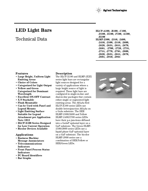
LED Light Bars Technical DataFeatures•Large Bright, Uniform Light Emitting Areas•Choice of Colors •Categorized for Light Output •Yellow and Green Categorized for Dominant Wavelength•Excellent ON-OFF Contrast •X-Y Stackable•Flush Mountable•Can be Used with Panel and Legend Mounts• Light Emitting Surface Suitable for Legend Attachment per Application Note 1012•HLCP-X100 Series Designed for Low Current Operation •Bicolor Devices Available Applications•Business MachineMessage Annunciators •Telecommunications Indicators•Front Panel Process Status Indicators•PC Board Identifiers•Bar Graphs DescriptionThe HLCP-X100 and HLMP-2XXXseries light bars are rectangularlight sources designed for avariety of applications where alarge bright source of light isrequired. These light bars areconfigured in single-in-line anddual-in-line packages that containeither single or segmented lightemitting areas. The AlGaAs RedHLCP-X100 series LEDs usedouble heterojunction AlGaAs ona GaAs substrate. The HERHLMP-2300/2600 and YellowHLMP-2400/2700 series LEDshave their p-n junctions diffusedinto a GaAsP epitaxial layer on aGaP substrate. The Green HLMP-2500/2800 series LEDs use aliquid phase GaP epitaxial layeron a GaP substrate. The bicolorHLMP-2900 series use acombination of HER/Yellow orHER/Green LEDs.HLCP-A100, -B100, -C100,-D100, -E100, -F100, -G100,-H100HLMP-2300, -2350, -2400,-2450, -2500, -2550, -2600,-2620, -2635, -2655, -2670,-2685, -2700, -2720, -2735,-2755, -2770, -2785, -2800,-2820, -2835, -2855, -2870,-2885, -2950, -2965Selection GuideLight Bar Part Number Corresponding Size ofPackage Panel and HLCP-HLMP-Light Emitting AreasOutlineLegend Mount Part No. HLMP-AlGaAs HER Yellow Green A1002300240025008.89 mm x 3.81 mm 1A 2599(.350 in. x .150 in.)B10023502450255019.05 mm x 3.81 mm 1B 2598(.750 in. x .150 in.)D1002600270028008.89 mm x 3.81 mm 2D 2898(.350 in. x .150 in.)E1002620272028208.89 mm x 3.81 mm 4E 2899(.350 in. x .150 in.)F100263527352835 3.81 mm x 19.05 mm 2F 2899(.150 in. x .750 in.)C1002655275528558.89 mm x 8.89 mm 1C 2898(.350 in. x .350 in.)G1002670277028708.89 mm x 8.89 mm 2G 2899(.350 in. x .350 in.)H1002685278528858.89 mm x 19.05 mm 1H 2899(.350 in. x .750 in.)295029508.89 mm x 8.89 mm Bicolor I 2898(.350 in. x .350 in.)296529658.89 mm x 8.89 mm BicolorI2898(.350 in. x .350 in.)Number of Light Emitting AreasPart Numbering SystemHLCP- xx xx-xx x xxHLMP-xx xx-xx x xxMechanical Options[1]00: No mechanical optionColor Bin Options[1,2]0: No color bin limitationB: Color bins 2 & 3 (applicable for yellow devices only)C: Color bins 3 & 4 only (applicable for green devices only)Maximum Intensity Bin[1,2]0: No maximum intensity bin limitationMinimum Intensity Bin[1,2]0: No minimum intensity bin limitationDevice Specific Configuration[1]Refer to respective data sheetColor[1]x1: AlGaAs Red (applicable for HLCP-x100 only)23: High Efficiency Red24: Yellow25: Green26: High Efficiency Red27: Yellow28: Green29: Bicolor (High Efficiency Red/Yellow) OR (High Efficiency Red/Green) Notes:1. For codes not listed in the figure above, please refer to the respective data sheet or contact your nearest Agilent representativefor details.2. Bin options refer to shippable bins for a part-number. Color and Intensity Bins are typically restricted to 1 bin per tube(exceptions may apply). Please refer to respective data sheet for specific bin limit information.Package DimensionsNOTES:1. DIMENSIONS IN MILLIMETRES (INCHES). TOLERANCES ±0.25 mm (±0.010 IN.) UNLESS OTHERWISE INDICATED.2. FOR YELLOW AND GREEN DEVICES ONLY.Internal Circuit DiagramsIAbsolute Maximum RatingsHER Yellow GreenAlGaAs Red HLMP-2300/HLMP-2400/HLMP-2500/ ParameterHLCP-X1002600/29XX2700/29502800/2965Series Series Series Series Average Power Dissipated per LED Chip37 mW[1]135 mW[2]85 mW[3]135 mW[2] Peak Forward Current per LED Chip45 mA[4]90 mA[5]60 mA[5]90 mA[5] Average Forward Current per LED Chip15 mA25 mA20 mA25 mADC Forward Current per LED Chip15 mA[1]30 mA[2]25 mA[3]30 mA[2] Reverse Voltage per LED Chip 5 V 6 V[6]Operating Temperature Range–20°C to +100°C[7]–40°C to +85°C–20°C to +85°C Storage Temperature Range –40°C to +85°CWave Soldering Temperature250°C for 3 seconds1.6 mm (1/16 inch) below BodyNotes:1.Derate above 87°C at 1.7 mW/°C per LED chip. For DC operation, derate above 91°C at 0.8 mA/°C.2.Derate above 25°C at 1.8 mW/°C per LED chip. For DC operation, derate above 50°C at 0.5 mA/°C.3.Derate above 50°C at 1.8 mW/°C per LED chip. For DC operation, derate above 60°C at 0.5 mA/°C.4.See Figure 1 to establish pulsed operation. Maximum pulse width is 1.5 mS.5.See Figure 6 to establish pulsed operation. Maximum pulse width is 2 mS.6.Does not apply to bicolor parts.7.For operation below –20°C, contact your local Agilent sales representative.Electrical/Optical Characteristics at T A = 25°CAlGaAs Red HLCP-X100 SeriesParameter HLCP-Symbol Min.Typ.Max.Units Test ConditionsA100/D100/E100I V37.5mcd I F = 3 mA Luminous Intensityper Lighting Emitting B100/C100/F100/G100615mcdArea[1]H1001230mcdPeak WavelengthλPEAK645nmDominant Wavelength[2]λd637nmForward Voltage per LED V F 1.8 2.2V I F = 20 mA Reverse Breakdown Voltage per LED V R515V I R = 100 µA Thermal Resistance LED Junction-to-Pin RθJ-PIN250°C/W/LEDParameter HLMP-Symbol Min.Typ.Max.Units Test Conditions2400/2700/2720IV 620mcd IF= 20 mALuminous Intensityper Lighting Emitting2450/2735/2755/2770/2950[3]1338mcd Area[1]27852670mcdPeak WavelengthλPEAK583nmDominant Wavelength[2]λd585nmForward Voltage per LED VF 2.1 2.6V IF= 20 mAReverse Breakdown Voltage per LED[5]VR 615V IR= 100 µAThermal Resistance LED Junction-to-Pin RθJ-PIN 150°C/W/LEDHigh Efficiency Red HLMP-2300/2600/2900 SeriesParameter HLMP-Symbol Min.Typ.Max.Units Test Conditions2300/2600/2620IV 623mcd IF= 20 mALuminous Intensityper Lighting Emitting2350/2635/2655/2670/2950[3]1345mcd Area[1]2965[4]1945mcd26852280mcdPeak WavelengthλPEAK635nmDominant Wavelength[2]λd626nmForward Voltage per LED VF 2.0 2.6V IF= 20 mAReverse Breakdown Voltage per LED[5]VR 615V IR= 100 µAThermal Resistance LED Junction-to-Pin RθJ-PIN 150°C/W/LEDYellow HLMP-2400/2700/2950 SeriesHigh Performance Green HLMP-2500/2800/2965 SeriesParameter HLMP-Symbol Min.Typ.Max.Units Test Conditions2500/2800/2820IV 525mcd IF= 20 mALuminous Intensityper Lighting Emitting2550/2835/2855/28701150mcd Area[1]2965[4]2550mcd288522100mcdPeak WavelengthλPEAK565nmDominant Wavelength[2]λd572nmForward Voltage per LED VF 2.2 2.6V IF= 20 mAReverse Breakdown Voltage per LED[5]VR 615V IR= 100 µAThermal Resistance LED Junction-to-Pin RθJ-PIN 150°C/W/LEDNotes:1.These devices are categorized for luminous intensity. The intensity category is designated by a letter code on the side of the package.2.The dominant wavelength, λd , is derived from the CIE chromaticity diagram and is the single wavelength which defines the color of thedevice. Yellow and Green devices are categorized for dominant wavelength with the color bin designated by a number code on the side of the package.3.This is an HER/Yellow bicolor light bar. HER electrical/optical characteristics are shown in the HER table. Yellow electrical/opticalcharacteristics are shown in the Yellow table.4.This is an HER/Green bicolor light bar. HER electrical/optical characteristics are shown in the HER table. Green electrical/opticalcharacteristics are shown in the Green table.5.Does not apply to HLMP-2950 or HLMP-2965.Figure 1. Maximum Allowable Peak Current vs. Pulse Duration.Figure 4. Forward Current vs. Forward Voltage.Figure 5. Relative Luminous Intensity vs. DC Forward Current.AlGaAs RedFigure 2. Maximum Allowed DC Current per LED vs.Ambient Temperature, T J MAX = 110°C.Figure 3. Relative Efficiency (Luminous Intensity per UnitCurrent) vs. Peak LED Current.For a detailed explanation on the use of data sheet information and recommended soldering procedures,see Application Notes 1005, 1027, and 1031.HER, Yellow, GreenFigure 9. Forward Current vs. Forward Voltage Characteristics.Figure 10. Relative Luminous Intensity vs. DC ForwardCurrent.Figure 6. Maximum Allowed Peak Current vs. Pulse Duration.Figure 7. Maximum Allowable DC Current per LED vs.Ambient Temperature, T J MAX = 100°C.Figure 8. Relative Efficiency (Luminous Intensity per Unit Current) vs. Peak LED Current.Intensity Bin Limits (mcd)HLMP-2300/2600/2620 Annunciators (.2 x .4 HER/AlGaAs), HLCP-A100/D100/E100IV Bin Category Min.Max.A 3.00 5.60B 4.508.20C 6.8012.10D10.1018.50E15.3027.80F22.8045.50G36.9073.80Notes:1. Minimum category A for Red L/C AlGaAs (-A100/-D100/-E100).2. Minimum category C for HER (-2300/-2600/-2620).HLMP-2350/2635/2655/2670 Annunciators (.2 x .8 HER/AlGaAs), HLCP-B100/C100/F100/G100 (.4 x .4 HER/AlGaAs)IV Bin Category Min.Max.A 5.4010.90B9.0016.00C13.1024.00D19.7036.10E29.6054.20F44.9088.80G71.90143.80Notes:1. Minimum category A for Red L/C AlGaAs (-B100/-C100/-F100/-G100).2. Minimum category C for HER (-2350/-2635/-2670).HLMP-2685/HLCP-H100 Annunciators (.4 x .8 HER/AlGaAs) IV Bin Category Min.Max.A10.8022.00B18.0027.10C22.0040.80D33.3061.10E50.0091.80F75.10150.00G121.70243.40Notes:1. Minimum category A for Red L/C AlGaAs (-H100).2. Minimum category C for HER (-2685).HLMP-2400/2700/2720 Annunciators (.2 x .4 Yellow)IV Bin Category Min.Max.C 6.1011.20D9.2016.80E13.8025.30F20.7041.40G33.6067.20HLMP-2450/2735/2755/2770 Annunciators (.2 x .8 Yellow & .4 x .4 Yellow) IV Bin Category Min.Max.C13.0022.00D18.0033.00E27.0050.00F40.5081.00G65.60131.20HLMP-2785 Annunciators (.4 x .8 Yellow)IV Bin Category Min.Max.C26.0044.40D36.0066.00E54.0099.00F81.00162.00G131.40262.80HLMP-2500/2800/2820 Annunciators (.2 x .4 Yellow)IV Bin Category Min.Max.C 5.6010.20D8.4015.30E12.6023.10F18.9037.80G30.6061.20H49.5097.90I80.10158.40HLMP-2550/2835/2855/2870 Annunciators (.2 x .8/.4 x .4 Green) IV Bin Category Min.Max.C11.3020.60D17.0031.00E25.4046.50F38.1076.20G61.60123.20H99.81197.67I161.73320.21HLMP-2885 Annunciators (.4 x .8 Green)IV Bin Category Min.Max.C22.2040.80D33.4061.20E50.1091.90F75.10150.30G121.10242.20H196.10383.50I313.70613.60HLMP-2950 Bi-Color Annunciators (.4 x .4 HER/Yellow) IV Bin Category Min.Max.Red Iv CategoriesC11.3020.60D17.0031.00E25.4046.50F38.1076.20G61.60123.20Yellow Iv CategoriesC13.0022.00D18.0033.00E27.0050.00F40.5081.00G65.60131.20HLMP-2965 Bi-Color Annunciators (.4 x .4/.2 x .8 HER/Green) IV Bin Category Min.Max.Red Iv CategoriesD19.7036.10E29.6054.20F44.9088.80G71.90143.80Green Iv CategoriesB7.5013.90C11.3020.60D17.0031.00E25.4046.50F38.1076.20G61.60123.20H100.00200.00Notes:1. Minimum category D for LPE Green (-2965).2. In green mode, the devices are to be color binned into standard color bins, perTable 2. (-2685).Color CategoriesNote:All categories are established for classification of products. Products may not be available in all categories. Please contact your local Agilent representatives for further clarification/information.I AVG I v TIME AVG =I TESTwhere:I TEST =3 mA for AlGaAs Red(HLMP-X000 series)20 mA for HER,Yellow and Green (HLMP-2XXX series)Example:For HLMP-2735 series ηI PEAK = 1.18 at I PEAK = 48 mA12 mA I v TIME AVG =20 mA= 25 mcd[][]ElectricalThese light bars are composed of two, four, or eight light emitting diodes, with the light from each LED optically scattered to form an evenly illuminated light emitting surface.The anode and cathode of each LED is brought out by separate pins. This universal pinoutarrangement allows the LEDs to be connected in three possible configurations: parallel, series, or series parallel. The typical forward voltage values can be scaled from Figures 4 and 9.These values should be used to calculate the current limiting resistor value and typical power consumption. Expected maximum V F values for driver circuit design and maximum power dissipation,may be calculated using the following V F MAX models:AlGaAs Red HLCP-X100 series V F MAX = 1.8 V + I Peak (20 Ω)For: I Peak ≤ 20 mAV F MAX = 2.0 V + I Peak (10 Ω)For: 20 mA ≤ I Peak ≤ 45 mA HER (HLMP-2300/2600/2900),Yellow (HLMP-2400/2700/2900)and Green (HLMP-2500/2800/2900) seriesV F MAX = 1.6 + I Peak (50 Ω)For: 5 mA ≤ I Peak ≤ 20 mA V F MAX = 1.8 + I Peak (40 Ω)For: I Peak ≥ 20 mAThe maximum power dissipation can be calculated for any pulsed or DC drive condition. For DC operation, the maximum powerdissipation is the product of the maximum forward voltage and the maximum forward current. For pulsed operation, the maximum power dissipation is the product of the maximum forward voltage at the peak forward current times the maximum average forward current. Maximum allowable power dissipation for any given ambient temperature and thermal resistance (R θJ-A ) can be deter-mined by using Figure 2 or 7. The solid line in Figure 2 or 7 (R θJ-A of 600/538 C/W) represents a typical thermal resistance of a device socketed in a printed circuitboard. The dashed lines represent achievable thermal resistances that can be obtained through improved thermal design. Once the maximum allowable power dissipation is determined, the maximum pulsed or DC forward current can be calculated.OpticalSize of Light Surface Area Emitting Area Sq. Metres Sq. Feet 8.89 mm x 8.89 mm 67.74 x 10–6729.16 x 10–68.89 mm x 3.81 mm 33.87 x 10–6364.58 x 10–68.89 mm x 19.05 mm 135.48 x 10–61458.32 x 10–63.81 mm x 19.05 mm72.85 x 10–6781.25 x 10–6The radiation pattern for these light bar devices is approximately Lambertian. The luminoussterance may be calculated using one of the two following formulas:I v (cd)L v (cd/m 2) =A (m 2)πI v (cd)L v (footlamberts) =A (ft 2)Refresh rates of 1 kHz or faster provide the most efficientoperation resulting in the maxi-mum possible time average luminous intensity.The time average luminousintensity may be calculated using the relative efficiency character-istic of Figure 3 or 8, ηI PEAK , and adjusted for operating ambient temperature. The time average luminous intensity at T A = 25°C is calculated as follows:(ηI PEAK ) (I v Data Sheet)(1.18) (35 mcd)The time average luminous intensity may be adjusted for operating ambient temperature by the following exponential equation:I v (T A) = I V (25°C)e[K (T –25°C)]Color KAlGaAs Red–0.0095/°CHER–0.0131/°C Yellow–0.0112/°C Green–0.0104/°CExample:I v (80°C) = (25 mcd)e[-0.0112 (80-25)] = 14 mcd.MechanicalThese light bar devices may beoperated in ambient temperaturesabove +60°C without deratingwhen installed in a PC boardconfiguration that provides athermal resistance pin to ambientvalue less than 280°C/W/LED. SeeFigure 2 or 7 to determine themaximum allowed thermalresistance for the PC board,RθPC-A, which will permitnonderated operation in a givenambient temperature.To optimize device opticalperformance, specially developedplastics are used which restrictthe solvents that may be used forcleaning. It is recommended thatonly mixtures of Freon (F113)and alcohol be used for vaporcleaning processes, with animmersion time in the vapors ofless than two (2) minutesmaximum. Some suggested vaporcleaning solvents are Freon TE,Genesolv DES, Arklone A or K. A60°C (140°F) water cleaningprocess may also be used, whichincludes a neutralizer rinse (3%ammonia solution or equivalent),a surfactant rinse (1% detergentsolution or equivalent), a hotwater rinse and a thorough airdry. Room temperature cleaningmay be accomplished with FreonT-E35 or T-P35, Ethanol,Isopropanol or water with a milddetergent.For further information onsoldering LEDs please refer toApplication Note 1027.A/semiconductorsFor product information and a complete list ofdistributors, please go to our web site.For technical assistance call:Americas/Canada: +1 (800) 235-0312 or(916) 788-6763Europe: +49 (0) 6441 92460China: 10800 650 0017Hong Kong: (+65) 6756 2394India, Australia, New Zealand: (+65) 6755 1939Japan: (+81 3) 3335-8152 (Domestic/Interna-tional), or 0120-61-1280 (Domestic Only)Korea: (+65) 6755 1989Singapore, Malaysia, Vietnam, Thailand,Philippines, Indonesia: (+65) 6755 2044Taiwan: (+65) 6755 1843Data subject to change.Copyright © 2004 Agilent Technologies, Inc.Obsoletes 5962-7197EJuly 8, 20045988-2221EN。
HSC277中文资料
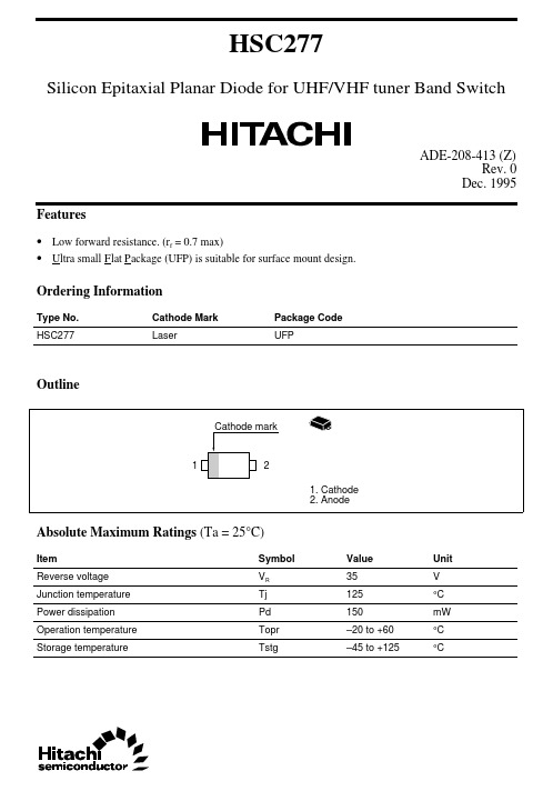
HSC277Silicon Epitaxial Planar Diode for UHF/VHF tuner Band SwitchADE-208-413 (Z)Rev. 0Dec. 1995 Features• Low forward resistance. (r f = 0.7max)• U l tra small F l at P a ckage (UFP) is suitable for surface mount design.Ordering InformationType No.Cathode Mark Package CodeHSC277Laser UFPOutlineAbsolute Maximum Ratings (Ta = 25°C)Item Symbol Value Unit35VReverse voltage VRJunction temperature Tj125°CPower dissipation Pd150mWOperation temperature Topr–20 to +60°CStorage temperature Tstg–45 to +125°CHSC2772Electrical Characteristics (Ta = 25°C)ItemSymbol Min Typ Max Unit Test Condition Reverse voltage V R 35——V I R = 10µA Reverse current I R ——50µA V R = 25V Forward voltage V F —— 1.0V I F = 10mA Capacitance C —— 1.2pF V R = 6V, f = 1MHz Forward resistancer f——0.7ΩI F = 2mA, f = 100MHzFig.1 Forward current Vs. Forward voltageHSC277Fig.2 Reverse current Vs. Reverse voltageFig.3 Capacitance Vs. Reverse voltage3HSC277Fig.4 Forward resistance Vs. Forward current 4HSC277 Package Dimensions5Cautions1.Hitachi neither warrants nor grants licenses of any rights of Hitachi’s or any third party’s patent,copyright, trademark, or other intellectual property rights for information contained in this document.Hitachi bears no responsibility for problems that may arise with third party’s rights, includingintellectual property rights, in connection with use of the information contained in this document.2.Products and product specifications may be subject to change without notice. Confirm that you have received the latest product standards or specifications before final design, purchase or use.3.Hitachi makes every attempt to ensure that its products are of high quality and reliability. However,contact Hitachi’s sales office before using the product in an application that demands especially high quality and reliability or where its failure or malfunction may directly threaten human life or cause risk of bodily injury, such as aerospace, aeronautics, nuclear power, combustion control, transportation,traffic, safety equipment or medical equipment for life support.4.Design your application so that the product is used within the ranges guaranteed by Hitachi particularly for maximum rating, operating supply voltage range, heat radiation characteristics, installationconditions and other characteristics. Hitachi bears no responsibility for failure or damage when used beyond the guaranteed ranges. Even within the guaranteed ranges, consider normally foreseeable failure rates or failure modes in semiconductor devices and employ systemic measures such as fail-safes, so that the equipment incorporating Hitachi product does not cause bodily injury, fire or other consequential damage due to operation of the Hitachi product.5.This product is not designed to be radiation resistant.6.No one is permitted to reproduce or duplicate, in any form, the whole or part of this document without written approval from Hitachi.7.Contact Hitachi’s sales office for any questions regarding this document or Hitachi semiconductor products.Hitachi, Ltd.Semiconductor & Integrated Circuits.Nippon Bldg., 2-6-2, Ohte-machi, Chiyoda-ku, Tokyo 100-0004, Japan Tel: Tokyo (03) 3270-2111 Fax: (03) 3270-5109Copyright ' Hitachi, Ltd., 1999. All rights reserved. Printed in Japan.Hitachi Asia Pte. Ltd.16 Collyer Quay #20-00Hitachi TowerSingapore 049318Tel: 535-2100Fax: 535-1533URLNorthAmerica : http:/Europe : /hel/ecg Asia (Singapore): .sg/grp3/sicd/index.htm Asia (Taiwan): /E/Product/SICD_Frame.htm Asia (HongKong): /eng/bo/grp3/index.htm Japan : http://www.hitachi.co.jp/Sicd/indx.htmHitachi Asia Ltd.Taipei Branch Office3F, Hung Kuo Building. No.167, Tun-Hwa North Road, Taipei (105)Tel: <886> (2) 2718-3666Fax: <886> (2) 2718-8180Hitachi Asia (Hong Kong) Ltd.Group III (Electronic Components)7/F., North Tower, World Finance Centre,Harbour City, Canton Road, Tsim Sha Tsui,Kowloon, Hong Kong Tel: <852> (2) 735 9218Fax: <852> (2) 730 0281 Telex: 40815 HITEC HXHitachi Europe Ltd.Electronic Components Group.Whitebrook ParkLower Cookham Road MaidenheadBerkshire SL6 8YA, United Kingdom Tel: <44> (1628) 585000Fax: <44> (1628) 778322Hitachi Europe GmbHElectronic components Group Dornacher Stra§e 3D-85622 Feldkirchen, Munich GermanyTel: <49> (89) 9 9180-0Fax: <49> (89) 9 29 30 00Hitachi Semiconductor (America) Inc.179 East Tasman Drive,San Jose,CA 95134 Tel: <1> (408) 433-1990Fax: <1>(408) 433-0223For further information write to:。
- 1、下载文档前请自行甄别文档内容的完整性,平台不提供额外的编辑、内容补充、找答案等附加服务。
- 2、"仅部分预览"的文档,不可在线预览部分如存在完整性等问题,可反馈申请退款(可完整预览的文档不适用该条件!)。
- 3、如文档侵犯您的权益,请联系客服反馈,我们会尽快为您处理(人工客服工作时间:9:00-18:30)。
DescriptionThese non-diffused lamps are designed to produce a bright light source and smooth radiationpattern. A slight tint is added to the lens for easy color identification.This lamp has been designed with aHLMP-C115, HLMP-C117, HLMP-C123, HLMP-C215, HLMP-C223,HLMP-C315, HLMP-C323, HLMP-C415, HLMP-C423, HLMP-C515,HLMP-C523, HLMP-C615, HLMP-C623Features•Very high intensity •Exceptional uniformity •Microtint lens for color identification•Consistent viewability All colors: AlGaAs RedHigh Efficiency Red Yellow Orange GreenEmerald Green •15° and 25° family•Tape and reel options available •Binned for color and intensity Applications•Ideal for backlighting front panels*•Used for lighting switches •Adapted for indoor and outdoor signsAgilentT-13/4 Super Ultra-Bright LED LampsData Sheet20mil lead frame, enhanced flange, and tight meniscus controls, making it compatible with radial lead automated insertion equipment.Selection GuidePart Number Luminous Intensity Iv (mcd) Color2θ1/2[1]Standoff Leads HLMP-Min.Max.DH AS AlGaAs15No C115290.0–C115-O00xx290.0–C115-OP0xx290.01000.0Yes C117-OP0xx290.01000.025No C12390.2–C123-L00xx90.2–Red15No C215138.0–C215-M00xx138.0–C215-MN0xx138.0400.025No C22390.2–C223-L00xx90.2–C223-MN0xx138.0400.0 Yellow15No C315147.0–C315-L00xx147.0–C315-LM0xx147.0424.025No C32396.2–C323-K00xx96.2–C323-KL0xx96.2294.0 Orange15No C415138.0–C415-M00xx138.0–C415-M0D0xx138.0–C415-MN0xx138.0400.025No C42390.2–C423-L00xx90.2–C423-LM0xx90.2276.0 Green15No C515170.0–C515-L00xx170.0C515-LM0xx170.0490.025No C52369.8–C523-J00xx69.8–C523-KL0xx111.7340.0 Emerald Green15No C61517.0–C615-G00xx17.0–25No C623 6.7–C623-E00xx 6.7–Part Numbering SystemHLMP - C x xx - x x x xxMechanical Options00: Bulk01: Tape & Reel, Crimped Leads02: Tape & Reel, Straight LeadsB2: Right Angle Housing, Even LeadsUQ: Ammo Pack, Horizontal LeadsColor Bin Options0: Full Color Bin DistributionD: Color Bins 4 & 5 onlyMaximum Iv Bin Options0: Open (No Maximum Limit)Others: Please refer to the Iv Bin TableMinimum Iv Bin OptionsPlease refer to the Iv Bin TableViewing Angle & Standoffs Options15: 15 Degree, without Standoffs17: 15 Degree, with Standoffs23: 25 Degree, without StandoffsColor Options1. AS AlGaAs Red2. High Efficiency Red3. Yellow4. Orange5. Green6. Emerald GreenPackage OptionsC: T-1 3/4 (5 mm)Absolute Maximum Ratings at T A = 25°CHighHighDH AS Efficiency Performance AlGaAs Red and Green and ParameterRed Orange Yellow Emerald Green Units DC Forward Current [1]30302030mA Transient Forward Current [2]500500500500mA (10 µsec Pulse)Reverse Voltage (Ir = 100 µA)5555V LED Junction Temperature 110110110110°C Operating Temperature Range –20 to +100–55 to +100–20 to +100°C Storage Temperature Range –55 to +100°CWave Soldering Temperature 250°C for 3 seconds [1.59 mm (0.063 in.) from body]Lead Solder Dipping Temperature 260°C for 5 seconds[1.59 mm (0.063 in.) from body]Notes:1. See Figure 5 for maximum current derating vs. ambient temperature.2. The transient current is the maximum nonrecurring peak current the device can withstand without damaging the LED die and wire bond.Package DimensionsHLMP-Cx15 and HLMP-Cx23HLMP-Cx17(0.039)NOTES:1. ALL DIMENSIONS ARE IN MILLIMETERS (INCHES).2. LEADS ARE MILD STEEL, SOLDER DIPPED.3. AN EPOXY MENISCUS MAY EXTEND ABOUT 0.5 mm (0.020 in.) DOWN THE LEADS.± 0.20± 0.008)Electrical Characteristics at T A = 25°CForward Reverse Capacitance Speed of ResponseVoltage Breakdown C (pF)Thermalτs (ns)Vf (Volts)Vr (Volts)Vf = 0Resistance Time Constant@ If = 20 mA@ Ir = 100 µA f = 1 MHz RθJ-PIN e-t/τsPart Number Typ.Max.Min.Typ.(°C/W)Typ.HLMP-C115 1.8 2.253021030HLMP-C117HLMP-C123HLMP-C215 1.9 2.651121090HLMP-C223HLMP-C315 2.1 2.651521090HLMP-C323HLMP-C415 1.9 2.654210280HLMP-C423HLMP-C515 2.2 3.0518210260HLMP-C523HLMP-C615 2.2 3.0518210260HLMP-C623Optical Characteristics at T A = 25°CLuminous Color,ViewingIntensity Peak Dominant Angle LuminousIv (mcd)Wavelength Wavelength2θ1/2Efficacy@ 20 mA[1]λpeak (nm)λd[2] (nm)(Degrees)[3]ηvPart Number Min.Typ.Typ.Typ.Typ.(lm/w) HLMP-C1152906006456371180HLMP-C117HLMP-C1239020026HLMP-C215138300635626171459017023HLMP-C315146300583585175009617025HLMP-C415138300600602173809017023HLMP-C515170300568570205956917028HLMP-C61517455585602065662728Notes:1. The luminous intensity, Iv, is measured at the mechanical axis of the lamp package. The actual peak of the spatial radiation pattern may not bealigned with this axis.2. The dominant wavelength, λd, is derived from the CIE Chromaticity Diagram and represents the color of the device.3. 2θ1/2 is the off-axis angle where the luminous intensity is 1/2 the on-axis intensity.Figure 1. Relative intensity vs. wavelength.Figure 2. Forward current vs. forward voltage (non-resistor lamp).Figure 3. Relative luminous intensity vs. forward current.WAVELENGTH – nmR E L A T I V E I N T E N S I T Y1.00.50I F – F O R W A R DC U R R E N T – m AV F – FORWARD VOLTAGE – VI F – F O R W A R D C U R R E N T – m AV F – FORWARD VOLTAGE – VHIGH EFFICIENCY RED, ORANGE,YELLOW, AND HIGH PERFORMANCEGREEN, EMERALD GREENR E L A T I V E L U M I N O U S I N TE N S I T Y (N O R M A L I Z E D A T 20 m A )I F – DC FORWARD CURRENT – mA R E L A T I V E L U M I N O U S I N T E N S I T Y (N O R M A L I Z E D A T 20 m A )0I DC – DC CURRENT PER LED – mA10201.60.80.4515301.2250.20.61.01.4HER, ORANGE, YELLOW, AND HIGH PERFORMANCE GREEN, EMERALD GREENFigure 5. Maximum forward dc current vs. ambient temperature. Derating based on T j MAX = 110°C.Figure 4. Relative efficiency (luminous intensity per unit current) vs. peak current.Figure 6. Relative luminous intensity vs. angular displacement. 15 degree family.R E L A T I V E E F F I C I E N C Y (N O R M A L I Z E D A T 20 m A )0I PEAK – PEAK FORWARD CURRENT – mA0.60.8300201001.21.00.20.45020010DH As AlGaAs REDηP E A K – R E L A T I V E E F F I C I E N C Y (N O R M A L I Z E D A T 20 m A )I PEAK – PEAK FORWARD CURRENT – mAHER, ORANGE, YELLOW, HIGHPERFORMANCE GREEN, EMERALD GREENI F – F O R W A R D C U R R E NT – m AT A – AMBIENT TEMPERATURE – °C DH As AlGaAs REDI F – F O R W A R D C U R R E N T – m AT A – AMBIENT TEMPERATURE – °CHER, ORANGE, YELLOW, AND HIGH PERFORMANCE GREEN, EMERALD GREEN N O R M A L I Z E D L U M I N O U S I N T E N S I T Y10ANGULAR DISPLACEMENT – DEGREES0.80.60.50.70.2450.10.30.4403530252010515-5-10-15-20-25-30-35-40-450.9Figure 7. Relative luminous intensity vs. angular displacement. 25 degree family.Intensity Bin Limits Intensity Range (mcd)ColorBin Min.Max.L 101.5162.4M 162.4234.6N 234.6340.0O 340.0540.0P 540.0850.0Q 850.01200.0R 1200.01700.0Red/OrangeS 1700.02400.0T 2400.03400.0U 3400.04900.0V 4900.07100.0W 7100.010200.0X 10200.014800.0Y 14800.021400.0Z 21400.030900.0L 173.2250.0M 250.0360.0N 360.0510.0O 510.0800.0P 800.01250.0YellowQ 1250.01800.0R 1800.02900.0S 2900.04700.0T 4700.07200.0U 7200.011700.0V 11700.018000.0W18000.027000.0N O R M A L I Z E D L U M I N O U S I N T E N S I T Y10ANGULAR DISPLACEMENT – DEGREES0.80.60.50.70.2450.10.30.4403530252010515-5-10-15-20-25-30-35-40-450.9Intensity Bin Limits, continuedIntensity Range (mcd) Color Bin Min.Max.E7.612.0F12.019.1G19.130.7H30.749.1I49.178.5J78.5125.7K125.7201.1L201.1289.0 Green/M289.0417.0 Emerald Green N417.0680.0O680.01100.0P1100.01800.0Q1800.02700.0R2700.04300.0S4300.06800.0T6800.010800.0U10800.016000.0V16000.025000.0W25000.040000.0 Maximum tolerance for each bin limit is ± 18%.Color CategoriesLambda (nm)Color Category #Min.Max.6561.5564.55564.5567.5 Green4567.5570.53570.5573.52573.5576.51582.0584.53584.5587.0 Yellow2587.0589.54589.5592.05592.0593.01597.0599.52599.5602.03602.0604.5 Orange4604.5607.55607.5610.56610.5613.57613.5616.58616.5619.5 Tolerance for each bin limit is ± 0.5 nm.Mechanical Option MatrixMechanical Option Code Definition00Bulk Packaging, minimum increment 500 pcs/bag01Tape & Reel, crimped leads, minimum increment 1300 pcs/bag02Tape & Reel, straight leads, minimum increment 1300 pcs/bagB2Right Angle Housing, even leads, minimum increment 500 pcs/bagUQ Ammo Pack, horizontal leads, in 1K minimum incrementNote:All categories are established for classification of products. Products may not be available in all categories. Please contact your local Agilent representative for further clarification/information./semiconductorsFor product information and a complete list ofdistributors, please go to our web site.For technical assistance call:Americas/Canada: +1 (800) 235-0312 or(916) 788-6763Europe: +49 (0) 6441 92460China: 10800 650 0017Hong Kong: (+65) 6756 2394India, Australia, New Zealand: (+65) 6755 1939Japan: (+81 3) 3335-8152 (Domestic/Interna-tional), or 0120-61-1280 (Domestic Only)Korea: (+65) 6755 1989Singapore, Malaysia, Vietnam, Thailand,Philippines, Indonesia: (+65) 6755 2044Taiwan: (+65) 6755 1843Data subject to change.Copyright © 2004 Agilent Technologies, Inc.Obsoletes 5965-6165ENovember 11, 20045988-2149EN。