欧姆龙液位开关说明书
欧姆龙说明书

1MC-510目录快速测量方法 (2)安全注意事项 (3)商品构成 (6)体温的基本常识 (8)测量方法 (9)电池更换方法 (17)有疑问时 (18)显示出错时 ................20保养与保管 ................22规格 ..........................23咨询 .. (24)产品保证书 (25)保修卡 .......................26非常感谢您购买欧姆龙速测体温宝,为了正确使 ⏹用本产品,请务必在使用之前阅读本产品说明书。
为了安全正确地使用本产品,请阅读并充分理解 ⏹本说明书中的“安全注意事项”。
敬请经常把说明书放在身边以便查阅。
⏹本说明书兼作产品质量保证书,故请妥善保管勿 ⏹丢失。
快速测量方法3说明书中所表示的警告记号和警告图例,其目的 ⏹是为了使您能够安全、正确地使用本产品,并防止对您及他人造成伤害。
警告记号、图例及其含义如下:⏹※ 所谓物品损坏是指有关房屋、家产及家畜、宠物的损害。
安全注意事项45建议• 当您把所测体温告诉医生时,请说明您是用耳式体温计进行测量的。
• 请不要用于人体耳部以外的体温测量。
• 请不要强行碰撞、摔落、踩踏和摇动本体。
•请勿在测量过程中在体温计附近使用移动电话。
• 请勿拆卸、修理和改造本体。
• 本产品不防水。
请注意不要让液体(酒精、水滴、热水等)进入本体内部。
6☆ 探测器保护罩是消耗品,使用完结后请购买新的探测器保护罩。
☆ 探测器保护罩脏污破损时,请更换探测器保护罩,因为表面的脏污和破损会影响测量精度。
78体温的基本常识测量腋下和舌下的体温易受外界温度、汗水和唾液等的影响,所以较之所测的温度偏低,而测量耳温可更好地反映脑部温度,快速测得正确的体温值。
为了正确判断发烧的状态,请了解正常情况下家庭成员的耳温。
耳温和腋下温度分布了解家庭成员正常状态时耳温。
耳温与腋下温度存在差异,通过正常状态时耳部与腋下的「温度差」可以大致比较出发烧时的「温度差」。
液位开关说明书

外贴式液位开关隔爆型安装使用说明书(201405A)陕西声科电子中国西安高新技术产业开发区©本说明书的版权和最终解释权归声科电子有限公司所用。
目录1.使用说明 (1)2.仪表保修及服务范围 (1)3.仪表技术性能 (2)4.开箱检验及注意事项 (2)4.1 开箱检验 (2)4.2 注意事项 (3)5.仪表各部件 (3)6.仪表安装 (4)6.1 超声波探头的安装 (4)6.2 仪表主机安装 (8)6.3仪表的安装方式 (11)7.仪表电气连接 (12)7.1 仪表电气连接图 (12)7.2 仪表供电 (12)8. 仪表设置及使用 (13)8.1 仪表参数设置人机接口说明 (13)8.2 仪表操作目录树 (14)8.3 仪表运行界面示意 (15)8.4 仪表校准操作 (16)8.5仪表校准操作图示 (16)9.外贴式液位开关选型表 (19)10.仪表适用范围 (20)11.性能指标 (20)12.仪表故障处理 (21)1、使用说明本说明书全面阐述了外贴式液位开关的安装、操作及使用方法。
通过本说明书,用户可以顺利的完成对外贴式液位开关的安装、使用及维护工作。
本说明书的编制是以外贴式液位开关的安装、操作步骤为顺序,详细介绍了您在安装、使用仪表的每个环节需要完成的工作及注意事项。
在您安装、使用该仪表之前,请详细阅读本说明书。
2、仪表保修及服务范围自发货之日算起,仪表主机保修期为一年,仪表修理及维护的保修期为半年,此保修仅限于原始购买者及或声科电子指定经销商的仪表使用用户,而不适用于任何声科电子认为因错误使用,改造、疏忽或因事故及非正常情况下使用而导致损坏的仪表。
对于在保修范围内的送回声科电子的有故障的仪表,声科电子提供免费维修。
要获得保修服务,请联系声科售后服务部并附上故障说明,经本公司许可后,将仪表寄往声科售后服务部。
如果仪表已过质保期或声科电子确认仪表故障是由于错误使用、改造、疏忽、事故及非正常条件下使用导致的,声科电子将依据外贴式液位开关维修收费标准提供维修费用预算,并在得到认可后进行维修。
欧姆龙元器件产品基础-61F.

基本型 如61F-G
底座型 如61F-GP-N
对应不同液位控制要求的61F型号
自动给/排水
带有水泵空转防止 或异常缺水报警的 自动给水系统 带有异常满水的自 动给水或排水系统 带有满水/缺水报警 的自动给水或排水
61F-GN/61F-GP/61F-GP-N(8)
61F-G1N/61F-G1/61F-G1P
61F-G2N/61F-G2/61F-G2P
61F-G3N/61F-G3
带有给水源上下限 指示/防水泵空转/ 排水水槽满水/缺水 报警的自动给水系统
仅做水位指示和报警
61F-G4N/61F-G4
61F-IN/61F-I/61F-IP
液位开关61F
液位开关的原理
液位开关是利用导电液体的导电性构成回路,产生一定电流并驱 动继电器进行输出的装置。 继电器 触点 电流
继电器
~
电源
电极棒 导电液体
液位开关广泛应用于 楼宇自动化中水箱的液位控 制、液体包装设备原料供应 罐的液位控制和锅炉液位控 制等。 电极棒
61F系列液位开关特点
-经济型高可靠性的电极式液位控制器 -有底座型、插入型、远距离型及高/低感度型(0-40㏀)等各种规 格,使用于不同场合、不同导电率液体的控制 -取代传统浮球式液位开关 -用于水泵控制系统中,可广泛应用于建筑、农用水、污水处理等各行 业的自动给排水系统中
61F的结构
61F控制器本体
电极保持器
电ห้องสมุดไป่ตู้棒
61F液位控制系统
LED指示灯
配置61F液位控制系统时应考虑以下 因素 61F控制器本体 61F控制器本体的安装方式 液位控制要求 使用环境和液体种类 电极棒的安装方式 液体化学特性及电极棒长度
欧姆龙温度控制器中文手册
输入
Pt100
901
温度范围 (选择使用 开关)
78
23
(默认设定: 0)
1,000 850 900
800
700
600
500
400
400
300 200 100
199.9
200
99
0 -100 -99
0.0
-99
0
0
设定编号 0
1
2
3
4
最小设定单位 1℃ 0.1℃
1℃
阴影部分的数值表示默认设定状态。 阴影部分的数值表示默认设定状态。
(䰏ᗻ䋳䕑)
cosφ = 1
1
0
1
2
3
4
5
6
ᓔ݇⬉⌕ (A)
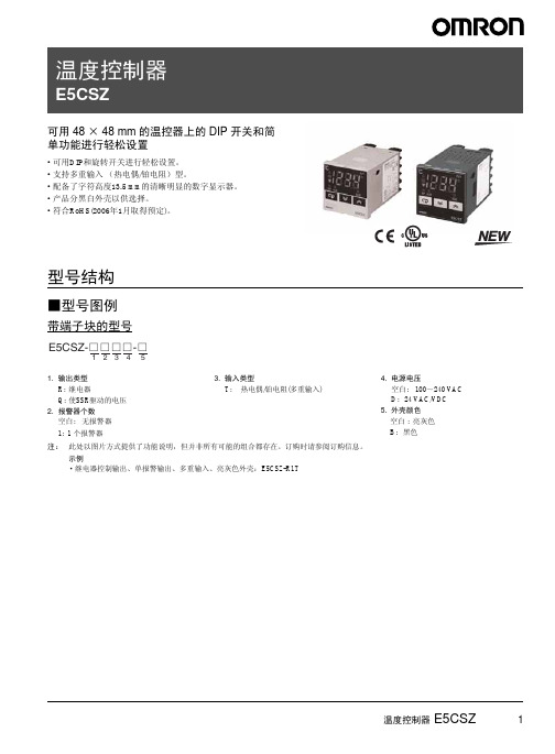
温度控制器 E5CSZ
3
■温度范围
多重输入 ( 热电偶 / 铂电阻 ) 型号
456 456
·使用热电偶传感器, 控制模式开关 5: OFF
输入
K
J
L
901
温度范围 (选择使用 开关)
78
23
(默认设定: 0)
1,700
1,600
1,500
1,400 1,300 1,300
1,200
1,100
1,000 900
850
850
800
700
600
500
400
300 200
199.9
199.9
100
0 -100 -99
0.0-990.0-99设定编号 0
1
2
3
4
最小设定单位 1℃ 0.1℃ 1℃ 0.1℃ 1℃
·使用铂电阻热电偶, 控制模式开关 5: ON
OMRON 限位开关 说明书
聚酰胺(尼龙)树脂
开关盒 密封橡胶
聚苯硫醚 铝(铸件) 锌(铸件)
丁腈橡胶
硅胶 氟化胶 氯丁二烯橡胶
材料记号 Au AuAg PGS AgPd
Ag
AgNi AgInSn C5210 C1700 C1720 C1700-□M C1720-□M SUS301-CSP SUS304-CSP PF PBTP PETP
接触形式 根据各种用途构成接点的电气输入输出电 路的方式。 树脂固定 (塑封端子) 用导线对端子部分完好配线, 通过充填树 脂使该部分固定, 消除暴露在外的带电部 分, 提高密封性的一种方法。
⚍ ᣛৃࡼ⠛ড䕀ᯊ㾺 ࠄⱘ䞥ሲ䚼ߚˈ䗮䖛 䖭辵㾺ᴹᅲ⦄⬉⇨ 䗮ǃᮁⱘϔ辵䳊ӊDŽ
⚍䯈䱨 ᣛᅮ⚍ৃࡼ⚍ ⱘ䯈䱨ǃ⚍鼠ࡼⱘ䎱 行DŽ
■EN60947-5-1规格用语
对目录中使用的上述规格用语说明如下。
ᓔ݇ ⎆ԡ䆒
⎆ԡ䆒 ᖂࡼᓔ݇ 䰤ԡᓔ݇ ᣝ䪂ᓔ݇ ᢼⷕᢼࡼᓔ݇ 䕏㾺ᓣᓔ݇ 㠍ൟᓔ݇ ᭄ᄫᰒ冫
ऩܗ
ᡔᴃᣛफ
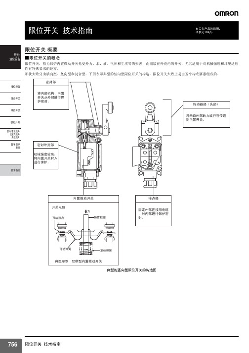
EN60947-5-1 「电气机械控制电路设备」的EN规格。 和IEC60947-5-1的内容相同。 使用范围 开关按用途来分类。 请参考下面的例子。
(1)活塞型 根据密封方法不同,有表中的A型和B型2个种类。 A型是用O型环 或薄膜密封的,由于密封橡胶没有外露,在抵制工作机械的切割碎 屑方面功能较强大,但其反面影响是,有可能会将砂子、切割粉末 等压入活塞的滑动面。B型虽然不会把砂子、切割粉末等压入,且 密封性能优于A型,但由于炽热的切割碎屑飞溅过来,有可能会损 坏橡胶帽。因此,要根据使用场所的不同选用A型或B型。而柱塞 型仍然通过柱塞的往复运动压缩或吸进空气。 为此,如果长时间将柱塞压入,限位开关内的压缩空气逸失,内部 压力将与大气压相同,即使急于让柱塞复位,柱塞却有迟缓复位的 倾向。为了避免发生这种故障,设计时请参见199页。
液位开关GP-N_中文说明书

■型号标准
61F-GP-□□
①②
①针型 N :11针 N8:8针
■种类
种类
11针型
一般用 型号
61F-GP-N(AC100V) 61F-GP-N(AC200V) 61F-GP-N(AC110V) 61F-GP-N(AC220V)
种类 11针型
高感度用 型号
61F-GP-NH(AC100V) 61F-GP-NH(AC200V)
E2 E3
˄ࡼᰒ冫ĀOFFā˅
P ᥦ∈
水面到达E1时 (动作显示 “ON”)泵停止,降到E2以下 (动作 显示 “OFF”)时起动。
水面到达E1时 (动作显示 “ON”)泵停止,降到E2以下 (动 作显示 “OFF”)时起动。
80 电极式液位开关(紧凑式插入型) 61F-GP-N□
使用液面显示时(连接例)
*2. 绝缘电阻、耐压指的是电源端子和电极端子间、电源端子和接点端子间、电极端子和接点端子间的数值。请参考第114页的 「使用注意事项」。
78 电极式液位开关(紧凑式插入型) 61F-GP-N□
项目
类型
一般用 61F-GP-N8
远距离用 61F-GP-N8L 2KM (2km用) 61F-GP-N8L 4KM (4km用)
61F-GP-N8H(AC200V) 61F-GP-N8HY(AC100V)
61F-GP-N8HY(AC200V)
注. 没有在上表中例出的电压请另外询问。
②种类 无标记 :一般用 L 2KM :远距离配线2km L 4KM :远距离配线4km
H :高感度用 D :低感度用 R :2线式用 T :高温用 (仅限于11针型)
额定电压的85%~110%
AC8V
OMRON ZW-系列液位传感器CJ系列EtherNet IP连接指南说明书

CJ SeriesEtherNet/IP™ Connection GuideOMRON CorporationZW-series Displacement SensorP536-E1-01About Intellectual Property Right and TrademarksMicrosoft product screen shots reprinted with permission from Microsoft Corporation.Windows is a registered trademark of Microsoft Corporation in the USA and other countries. ODVA and EtherNet/IP™ are trademarks of ODVA.Ethernet is a registered trademark of the Xerox Corporation.Company names and product names in this document are the trademarks or registered trademarks of their respective companies.Table of Contents1.Related Manuals (1)2.Terms and Definitions (2)3.Remarks (3)4.Overview (5)5.Applicable Devices and Support Software (6)5.1.Applicable Devices (6)5.2.Device Configuration (7)6.EtherNet/IP Connection Procedure (9)6.1.EtherNet/IP Communications Settings (9)6.2.Work Flow (12)6.3.Setting Up the Displacement Sensor (13)6.4.Setting Up the PLC (21)6.5.Checking the EtherNet/IP Communications (44)7.Initialization Method (49)7.1.Initializing the PLC (49)7.2.Initializing the Displacement Sensor (50)8.Revision History (51)1. Related Manuals1. Related ManualsThe table below lists the manuals related to this document.To ensure system safety, make sure to always read and heed the information provided in all Safety Precautions, Precautions for Safe Use, and Precaution for Correct Use of manuals for each device which is used in the system.Cat. No. Model Manual nameCJ-series CJ2 CPU Unit Hardware User's Manual W472 CJ2H-CPU6[]-EIPCJ2H-CPU6[]CJ2M-CPU[][]CJ-series CJ2 CPU Unit Software User's Manual W473 CJ2H-CPU6[]-EIPCJ2H-CPU6[]CJ2M-CPU[][]EtherNet/IP™ Unit Operation Manual W465 CJ1W-EIP21CJ2H-CPU6[]-EIPCJ2M-CPU3[]W446 - CX-Programmer Operation ManualZ332 ZW-CE1[] ZW Series Displacement Sensor (Confocal Fiber Type)User's Manual2. Terms and Definitions2. Terms and DefinitionsTerm Explanation and DefinitionTag data link A function that enables cyclic tag data exchanges on an EtherNet/IPnetwork between PLCs or between PLCs and with other devices withoutusing a user program in the PLCs.Tag A tag is a unit that is used to exchange data with tag data links. Data isexchanged between the local network variables and remote networkvariables specified in the tags or between specified I/O memory areas.Tag set When a connection is established, from 1 to 8 tags (including Controllerstatus) is configured as a tag set. Each tag set represents the data thatis linked for a tag data link connection.Connection A connection is used to exchange data as a unit within which datasynchronicity is maintained.Thus, data synchronicity is maintained for all the data exchanged for thetags in one data set.Originator and Target To perform tag data links, one node requests the opening of acommunications line called "connection" to perform tag data links.The node that requests opening the connection is called "originator",and the node that receives the request is called "target".Node With EtherNet/IP network, 1 node is 1 EtherNet/IP port.Tag data link parameter The tag data link parameter is the setting data to perform the tag data link. It includes the data to set tags, tag sets, and connections.EDS file A file that contains the I/O points of EtherNet/IP devices and the parameters that can be set via EtherNet/IP.3. Remarks(1) Understand the specifications of devices which are used in the system. Allow somemargin for ratings and performance. Provide safety measures, such as installing safetycircuit in order to ensure safety and minimize risks of abnormal occurrence.(2) To ensure system safety, always read and heed the information provided in all SafetyPrecautions, Precautions for Safe Use, and Precaution for Correct Use of manuals foreach device used in the system.(3) The users are encouraged to confirm the standards and regulations that the system mustconform to.(4) It is prohibited to copy, to reproduce, and to distribute a part of or whole part of thisdocument without the permission of OMRON Corporation.(5) This document provides the latest information as of April 2013. The information on thismanual is subject to change without notice for improvement.The following notation is used in this document.Precautions for Safe UsePrecautions on what to do and what not to do to ensure safe usage of the product.Precautions for Correct UsePrecautions on what to do and what not to do to ensure proper operation and performance.Additional InformationAdditional information to read as required.This information is provided to increase understanding or make operation easier.4. Overview4. OverviewThis document describes the procedure to connect the Displacement Sensor (ZW series) of OMRON Corporation (hereinafter referred to as OMRON) with CJ-series ProgrammableController + Ethernet/IP Unit (hereinafter referred to as the PLC ), and the procedure to check their connection.Refer to Section 6. Connection Procedure to understand the setting method and key points to connect the devices via EtherNet I/P.In this document, CJ-series EtherNet/IP Unit and the built-in EtherNet/IP port of CJ-series CJ2 CPU Unit are collectively called as the "EtherNet/IP Unit".5. Applicable Devices and Support Software5.1. Applicable DevicesThe applicable devices are as follows:Manufacturer Name ModelOMRON CJ2 CPU Unit CJ2[]-CPU[][]OMRON EtherNet/IPUnit CJ1W-EIP21CJ2H-CPU6[]-EIPCJ2M-CPU3[]OMRON ConfocalFiberTypeDisplacement Sensor Controller ZW-CE1[] ZW-CE1[]TOMRON SensorHead ZW-S[][]Additional InformationAs applicable devices above, the devices with the models and versions listed in Section 5.2.are actually used in this document to describe the procedure for connecting devices and checking the connection.You cannot use devices with versions lower than the versions listed in Section 5.2.To use the above devices with versions not listed in Section 5.2 or versions higher than those listed in Section 5.2, check the differences in the specifications by referring to the manuals before operating the devices.Additional InformationThis document describes the procedure to establish the network connection. Except for the connection procedure, it does not provide information on operation, installation or wiring method. It also does not describe the functionality or operation of the devices. Refer to the manuals or contact your OMRON representative.5.2. Device ConfigurationThe hardware components to reproduce the connection procedure of this document are as follows:CJ2M-CPU32(Built-in EtherNet/IP port)Personal computer(CX-One installed)ZW-S40Calibration ROMPrecautions for Correct UseUpdate the CX-Programmer and Network Configurator to the versions specified in this section or higher versions using the auto update function.If a version not specified in this section is used, the procedures described in Section 6 and subsequent sections may not be applicable. In that case, use the equivalent procedures described in the CX-Programmer Operation Manual (Cat. No. W446) and Network Configurator Online Help.5. Applicable Devices and Support SoftwareAdditional InformationThe system configuration in this document uses USB for the connection between the personal computer and PLC. When installing the USB driver, please refer to A-5 Installing the USB Driver in the CJ-series CJ2 CPU Unit Hardware User's Manual (Cat. No. W472).6. EtherNet/IP Connection ProcedureThis section explains the procedure for connecting the Displacement Sensor to the PLC via EtherNet/IP.6.1. EtherNet/IP Communications SettingsThe settings shown in the table below are used to explain the procedure for connecting the PLC.This document explains the procedure for setting up the PLC and Displacement Sensor from the factory default setting. For the initialization, refer to Section 7 Initialization Method.6.1.1. SettingsThe settings of the PLC (EtherNet/IP Unit) and the Displacement Sensor are as follows:PLC (EtherNet/IP Unit)(node 1) Displacement Sensor(node 2)Unit number 0 -Node address 1 2IP address 192.168.250.1 192.168.250.2Subnet mask 255.255.255.0 255.255.255.0 (default)MEMLNK (Memory link function) - EIP(EtherNet/IP)6.1.2. Tag Data Link AllocationThe tag data link allocation of the Displacement Sensor is as follows:Output areaInput areaD10000D10011(PLC → DisplacementSensor) 24 bytesD10100D10127(Displacement Sensor →PLC) 56 bytes•Output area (PLC → Displacement Sensor) Bit15 14 13 12 11 10 9 87 6 54 3 21DescriptionD10000SYNC EXE D10001 ERCLR Control input *1(2 words)D10002LIGHT OFF RESET1 TMNG1 D10003 ZEROCLR_T4ZEROCLR_T3ZEROCLR_T2ZERO CLR_T1ZERO1_T4ZERO1_T3ZERO1 _T2 ZERO1_T1 Control input *2(2 words)D10004D10005Control input *3(2 words) D10006D10007Command code (2 words)- D10008Command parameter 1 CommandD10009Command parameter 2 parameters D10010D10011Command parameter 3(Up to 4 words)*1: Sensor head common control signal*2: Sensor head 1 control signal*3: Sensor head 2 control signal (Reserved)•Input area (Displacement Sensor → PLC)Bit15 14 13 12 11 10 98765 4 3 2 1 0 Description D10100 BANK1_EBANK1_DBANK1_CBANK1_BBANK1_ARUN READYSYNCFLGFLGD10101 ERRControloutput *1(2 words)D10102 OR1 GATE1ENABLE1STABLITY1LIGHT1RESETSTAT1HOLDSTAT1D10103 LOW1_T4PASS1_T4HIGH1_T4LOW1_T3PASS1_T3HIGH1_T3LOW1_T2PASS1_T2HIGH1_T2LOW1_T1PASS1_T1HIGH1_T1ZEROSTAT_T4ZEROSTAT_T3ZEROSTAT_T2ZEROSTAT_T1Controloutput *2(2 words) D10104D10105Controloutput *3(2 words) D10106D10107Command code (2 words) -D10108D10109Response code (2 words) -D10110D10111Response data (2 words) -D10112D10113Output data 0D10114D10115Output data 1D10116D10117Output data 2D10118D10119Output data 3D10120D10121Output data 4D10122D10123Output data 5D10124D10125Output data 6D10126D10127Output data 7Output data(16 words)*1: Sensor head common status signal*2: Sensor head 1 status signal*3: Sensor head 2 status signal (Reserved)Additional InformationFor details on the command codes and response codes, refer to 6-3 Ethernet/IP Connection under Chapter 6 Communications with External Devices in the ZW Series Displacement Sensor (Confocal Fiber Type) User's Manual (Cat. No. Z332).6.2. Work FlowTake the following steps to set the tag data link for EtherNet/IP.6.3 Setting Up the Displacement Sensor Set up the Displacement Sensor.↓6.3.1 Parameter Settings Set the parameters for the Displacement Sensor.↓6.4 Setting Up the PLC Set up the PLC.↓6.4.1 Hardware Settings Set the hardware switches on the EtherNet/IP Unit.↓6.4.2 Starting the CX-Programmer andConnecting Online with PLC Start the CX-Programmer and connect online with the PLC.↓6.4.3 Creating the I/O Table andSetting the IP Address Create the I/O table for the PLC and set the IP address.↓6.4.4 Starting the Network Configuratorand Uploading the Configuration Start the Network Configurator and upload the network configuration.↓6.4.5 Setting Tags Register the tags of the send area and receive area.↓6.4.6 Setting Connections Associate the tags of the target device with the tagsof the originator.↓6.4.7.Transferringthe Tag Data LinkParametersTransfer the set tag data link parameters to the PLC.↓6.5 Checking the EtherNet/IPCommunications Confirm that the EtherNet/IP communications are performed normally.↓6.5.1 Checking the Connection Status Check the connection status of EtheNet/IP.↓6.5.2 Checking Data that are Sent andReceivedConfirm that correct data are sent and received.6.3. Setting Up the Displacement SensorSet up the Displacement Sensor.6.3.1. Parameter Settings6.4. Setting Up the PLCSet up the PLC.6.4.1.Hardware SettingsSet the hardware switches on the EtherNet/IP Unit.Precautions for Correct UseMake sure that the power supply is OFF when you perform the setting up.1 Make sure that the PLC power is OFF.*If the power supply is turned ON, the following procedure may not be applicable.2 Refer to the right figure and check the hardware switcheslocated on the front panel of the EtherNet/IP Unit.3 Set the Unit number setting switch to 0.The unit number is used to identify individual CPU Bus Units when more thanone CPU Bus Unit is mounted to the same PLC. Use a small screwdriver to make the setting, taking care not to damage the rotary switch. The unit number is factory-set to 0.4 Set the node address setting switches to the following defaultvalues.[NODE No.x161]: 0 [NODE No.x160]: 1*Set the IP address to 192.168.250.1.*By default, the upper threeoctets are fixed to 192.168.250, and the values set with the node address setting switches are the fourth octet of the local IP address.With the FINS communications service, when there are multiple EtherNet/IP Units connected to the Ethernet network, the EtherNet/IP Units are identified by node addresses. Use the node address switches to set the node address between 01 and FE hexadecimal (1 to 254 decimal).Do not set a number that has already been set for another node on the same network.The left switch sets the sixteens digit (most significant digit) and the right switch sets the ones digit (least significant digit).The node address is factory-set to 01.Default IP address = 192.168.250.node addressWith the factory-default node address setting of 01, the default IP address is 192.168.250.1.PLCUSB cable LAN cable6.4.2. Starting the CX-Programmer and Connecting Online with PLCStart the CX-Programmer and connect online with the PLC.Install the CX-One and USB driver in the personal computer beforehand.Additional InformationIf the CX-Programmer and PLC are not connected online, please check the connection of the cable. Or, return to step 2, check the settings and perform each step again.Refer to Connecting Directly to a CJ2 CPU Unit Using a USB Cable in Chapter 3 Communications in PART 3: CX-Server Runtime of the CX-Programmer Operation Manual(Cat. No. W466) for details.Additional InformationThe dialogs explained in the following procedures may not be displayed depending on theenvironmental setting of CX-Programmer.For details on the environmental setting, refer to Options and Preferences in Chapter 3Project Reference in PART 1: CX-Programmer of the CX-Programmer Operation Manual(Cat. No. W466).This document explains the setting procedure when the setting item "Confirm all operationsaffecting the PLC" is selected.6.4.3. Creating the I/O Table and Setting the IP AddressCreate the I/O table for the PLC and set the IP address.6.4.4. Starting the Network Configurator and Uploading the ConfigurationStart the Network Configurator and upload the network configuration.Precautions for Correct UsePlease confirm that the LAN cable is connected before performing the following procedures.When it is not connected, turn OFF the power supply to each device and then connect the LAN cable.Hardware ListNetwork Configuration PaneAdditional InformationIf the CX-Programmer and PLC are not connected online, please check the connection of the cable. Or, return to step 1, check the settings and try each step again.For details, refer to 6-2-9 Connecting the Network Configurator to the Network in Section 6Tag Data Link Functions of the EtherNet/IP Unit Operation Manual (Cat. No. W465).6.4.5. Setting TagsRegister the tags of the receive area and send area.This section explains the receive settings and then send settings of the target node.Configurator, right-click the node-Here, register the send data of node 1. (Data sent from node 16.4.6. Setting ConnectionsAssociate the tags of target device (node that receives the open request) with the tags of originator (node that requests opening).■Settings of Connection Connection I/O type Consume Data From/Produce Data To Input Tag SetD10100 - [56Byte] Connection TypeMulti-cast connection Output Tag SetD10000 - [24Byte]Originator device Connection Type Point to Point connection Output Tag Set Input_101- [56Byte] Target DeviceInput Tag SetOutput_100- [24Byte]6.4.7. Transferring the Tag Data Link ParametersTransfer the set tag data link parameters to the PLC.6.5. Checking the EtherNet/IP CommunicationsConfirm that the EtherNet/IP communications are performed normally.6.5.1. Checking the Connection StatusCheck the connection status of EtherNet/IP .1 Confirm that the tag data links arenormally in operation by checking the status information on the Device Monitor Window of the Network Configurator.•PLC (EtherNet/IP Unit)LED indicators in normal status. [MS]: Lit green [NS]: Lit green [COMM]: Lit yellow [100M] or [10M]: Lit yellow•Displacement SensorDuring normal connection, the red and green indicators on the ETHERNET connector are lit.(EtherNet/IP Unit)(Displacement Sensor Controller)2 Confirm that the tag data links arenormally in operation by checking the status information on the DeviceMonitor Window of the Network Configurator.Right-click the device icon of node 1 on the Network Configuration Pane and select the Monitor .Number: Node number Blue: Connection normal6.5.2. Checking Data that are Sent and ReceivedConfirm that correct data are sent and received.Confirm safety sufficiently before monitoring power flow and present value status in the Ladder Section window or before monitoring present values in the Watch window. If force-set/reset or set/reset operations areincorrectly performed by pressing short-cut keys, the devices connected to Output Units may malfunction, regardless of the operating mode of the CPU Unit.。
液位控制器说明书

液位控制器说明书
液位报警控制器是一种监测液位并在液位到达一定高度或低度时发出警报的设备。
以下是液位报警控制器的使用说明:
1.确定液位报警器的安装位置,通常应该安装在容器的顶部或底部,以便能够准确感测液位变化。
2.连接电源:第一步需要为液位报警控制器连接电源。
根据设备的要求和安装位置,使用正确的电源线为设备供电。
3.连接传感器:将传感器连接到液位报警控制器。
传感器应该安装在容器的顶部或底部,根据设备的要求和安装要求完成连接。
4.设置警报值:根据需要设置液位报警器的警报值。
设置过程可能会因不同的设备而有所不同。
对于某些设备,用户可以使用按钮或旋钮来设置液位警报值。
5.测试设备:完成液位报警器的安装和设置后,请测试设备以确保其正常工作。
通常可以将容器注满水,并检查液位控制器是否发出警报。
6.日常维护:在使用过程中,需要对液位报警器进行定期维护。
通常可以使用软毛刷或擦布清洗传感器,以确保液位报警器的精度和可靠性。
- 1、下载文档前请自行甄别文档内容的完整性,平台不提供额外的编辑、内容补充、找答案等附加服务。
- 2、"仅部分预览"的文档,不可在线预览部分如存在完整性等问题,可反馈申请退款(可完整预览的文档不适用该条件!)。
- 3、如文档侵犯您的权益,请联系客服反馈,我们会尽快为您处理(人工客服工作时间:9:00-18:30)。
开关液位设备概要选择机型的标准故障检查液位设备Q&A关于施工资料参考电极式液位开关(61F)作为电气性液位检测方式,被广泛用于以大厦、集中住宅的上下水道为主及钢铁、食品、化学、药品、半导体等各种工业、农业水、净水场、污水处理等的液面控制。
一旦电极接触到液体,通过液体可以闭合电路(电气流通的道路),根据流过的电流检知液位控制的动作原理,是以所谓的导电性液体为控制对象的液位开关。
进行检测时,直接检测液体的电极间电阻,根据大于或小于已设定的电阻值,来判断有无液面。
■基本原理以一般接收上水道供水的情况为例来进行说明。
通常,在大厦、集中住宅区等中,一旦接水槽接收供水后,就会将水送到设置在屋顶上的高架水槽内,然后再分配到各楼层。
在高架水槽内,如果因水的消耗而导致水槽内的水位下降,通过泵从接水槽中再进行补充。
达到一定的水位后,即可停止泵了。
(参照图1)在高架水槽内,可以进行水位的控制,以保持上限和下限间的水位。
可以根据下列工作原理来进行这一水位控制。
图1. 水槽的供水控制●根据水位对泵进行ON、OFF控制(2根电极式)①如图2,电极E1未接触到液面时,电流流通的电路(E1-E3间)为开路,没有电流通过。
因此,继电器「X」不动作,继电器「X」的接点仍为“b侧”。
②如图3,电极E1接触到液面时,为电路闭合状态(液体将E1-E3间闭合),因此,继电器「X」动作,接点移动到“a侧”。
若将该继电器接点连接到接触器,则可根据液面的位置对泵进行ON、OFF控制。
但是,如图2、图3,如果仅有2根电极,电极E1附近会发生波动,导致继电器抖动。
为此,电极式液位开关有自我保持电路。
(图2、图3用于水位的报警等方面)图2 水位低时图3 水位高时●带自我保持电路的实用性水位控制(3根电极式)如图4所示,使用E1、E3电极以外的E2电极,通过a2接点连接E2、E1。
此时(前页的②)液面接触电极E1、继电器「X」动作,如果接点变为“a侧”,即使接下来液面低于E1,E2-E3间的电路也可以保持闭合状态。
这种E2电极和接点构成的电路称为自我保持电路。
如果液面低于E2,为使电路再次打开、继电器「X」复位到“b侧”,可以在E1-E2间对继电器[X]进行ON、OFF控制。
图5表示该动作的时间图。
由于这种动作方式简单,除了液位控制,电极式液位开关还应用于接触开关、漏水检测器、进行大小判别的传感器等。
图4 自我保持电路图5时间图请注意:在油之类不能通电的液体中,不能根据本方式进行液面控制。
●净水用于饮用的净化水,一般指送到家庭的水、自来水。
使用泵送到指定地方的水。
多为抽取自来水。
而净化槽,是指净化污水的槽,不要混淆。
●使用水有目的地储放的水,多为与自来水有相同灵敏度的水。
如防火用水等。
. ●污水是流向下水道前的水,一般指厕所的排水。
[参考]家庭、工厂的排水中含有固体物、浮游物,且液体也是低电阻,因此必须考虑电极的设置。
●上水(自来水)[参考]基本上与净水的意思相同。
对下水来说是上水,在水道局也有上水道和下水道之分。
在水道局,净化前的水也称为上水,比净水意思更广。
●下水(下水道)与其说是水的种类,还不如说是污水流动的体系。
发达国家的下水道是很完善的。
在一些大城市,下水道完善的地方较多,这种情况下,无需净化槽,直接流出污水排杂槽。
另外,也有一些地方没有设置污水排杂槽,而往往会直接将流出污水的管子连接到下水道。
●雨水61F-GN-NH3指积留在水坑等地方的雨水。
与净水相比,电阻稍高。
●涌出水指像泉水一样涌出的水。
●循环水与雨水相同,电阻稍高●抽水使用泵送到指定地方的水。
多为抽取自来水。
●使用水有目的地储放的水,多为与自来水有相同灵敏度的水。
如防火用水等。
●离子交换水是指除去离子成分的水。
除去离子成分的方法不是蒸馏,因此是高电阻。
[参考]一般使用的水为动作电阻200kΩ更有时使用61F-GP-NH3 ,但使用除去离子成分的方法后,电阻值会提高。
(纯水)●蒸馏水一般为收集的水蒸汽,但电阻比纯水低。
[参考]可以用高灵敏度用的61F。
●循环水锅炉蒸汽的循环水。
在管道中,指蒸汽成为水滴形成的水。
●纯水指不含不纯物质的水。
事例如下,从200kΩ·cm开始,高达18MΩ·cm位,必须使用超高灵敏度的61F 。
[参考]为纯水时,为确保水的纯度,应使用钛电极。
●冷凝水指蒸汽涡轮、锅炉等的冷却水。
指为使锅炉的热水保持一定的纯度而排放出来的水。
用于存放这种水的容器,其电阻应比一般用的稍低。
水槽·池●接水槽在大厦、公寓大楼等高层住宅屋顶上有高架水槽的地方,一旦水槽里储有水,就会在高架水槽内用泵将水吸上来。
这个水槽称为接水的水槽。
一般设置在地下室或一层。
[参考]在本样本目录中作为一般性的供水源,但在大厦以外的情况下不称为接水槽。
它多与消防用的消防栓共用,选择电极的长度时必须考虑这些。
接水槽本身的液位控制,通过另外的61F 或球形旋塞来进行。
(也有和高架水槽用的61F的电极一起接入的情况)在稍微大点的大厦、公寓大楼中使用61F-G4N。
●高架水槽指设置在大厦、公寓大楼等高层住宅屋顶上的,利用高度来提供水槽。
[参考]从接水槽61F-G4N或61F-GIN 等自动地将水泵上来。
最近引进了直接施加压力进行送水的系统(压送式),也可用于?不带高架水槽的大厦,在停电、天灾等情况下,人们重新认识了储水罐的作用。
指相对于水源地,将从水源地分配到的暂时性蓄水,提供到住宅的池。
设于分支用的小型水源地。
●污水排杂槽在下水道完善的城市中,作为净化水槽的替代品,积蓄来自厕所的污水和厨房的排水。
[参考]对于普通的公寓大楼等,是从污水管道直接流到下水道,但是对于有地下室的大楼,必须到下水道用泵将水吸上来。
为此,必须在地下设置积蓄污水的槽。
此时,油、固体物会直接进入,因此,设置电极时,必须每隔1 极设置,并防止电极间的短路。
●水源池指水道局为给居民用的水道供水而造的池等。
无论何种形式下,从各种水源将水送到这里,通过净化装置为市民供水。
[参考]水源池通常应保持一定的水位,多使用61F,继电器和电极间的布线非常长的地方也有很多。
除公共场所以外,也有一些私设水源地的地方●净化槽收集厕所的排水,暂且在这里进行净化。
即在无固体物的状态下将其排放到其他地方。
[参考]由于净化槽中环境为弱碱,因此必须注意绝缘。
在下水道完善的城市,大厦等无需净化槽的地方也较多,而将其转移到污水排杂槽。
规格●动作电阻指61F本体进行动作所需的电极间的电阻值,如果液体或固体的电极间电阻值低于该值,就一定会动作。
[参考]即使在该值很高不易导通的液体中,也能动作,这时需要高灵敏度。
●电极间电阻大致与动作电阻相同。
从61F的输入(电极)到61F本体有动作电阻、布线有可能是长距离,因此不一定相同,但一般情况下认为是相同也是没问题的。
●导电率(西门子:S)表示液体导电度的单位。
最近用微西门子(μS)来表示(以前是姆欧:)。
由于是电阻的倒数,值越小电阻就会变得越高,因此必须为高灵敏度。
1μS/cm →1MΩ·cm2μS/cm → 500kΩ·cm10μS/cm → 100kΩ·cm●自我保持如果继电器工作,记忆保持这一状态的功能就是自我保持。
为61F-GN时,E2电极就会变为自我保持用。
根据具备的自我保持功能考虑控制的幅度,另外,可防止由于液面的波动引起的继电器抖动。
●接点容量(输出)61F可开关负载容量。
●复位电阻61F本体进行复位所需的电极间的电阻值,如果高出该值,61F就会复位。
[参考]一般情况下,如果没有液体,电阻将会变为无穷大,但是,由于电极保持器、分离器等上面附着了液体,因此不能马上变为无穷大。
61F中,多数情况下该值较为重要(根据布线的不同,还会影响到漏电流),低灵敏度用、远距离用就是因为这一原因。
●固有电阻表示液体电流流动的难易度,单位为kΩ·cm.为电导率成倒数的关系。
(请注意,与动作电阻不同)通过液体使电气在电极棒间的无数线路流通。
固有电阻表示这一电气流通的难易度。
由于固有电阻根据电极的设置条件、浸水长度而有所不同,因此,实际设备的动作是根据电极的间隔、表面积(浸水长度)确定的。
要求出电极间电阻较困难,因此以固有电阻为标准。
●动作电压指61F动作所需的电源电压。
61F的动作电压为额定电压的85%以上。
因此,注意不要使电源电压在85%以下。
●最小适用负载电子电路等非常小的负载(微小负载)的可开关界限的标准。
●接点构成指接点的接触机构。
[参考]●负载分为以下3种⑴阻性负载指如果施加电压,就会一直流通相同值电流的负载,如加热器。
⑵感性负载指含有电感的负载,如电机、螺线管等。
⑶容性负载指含有电抗的负载,如电容器等。
[参考]●冲击电流闭合接点的瞬间,大于稳定状态的过渡性流入电流。
●预动作方式61F 本体施加控制电源的同时,内置继电器动作,电极间流入电流就会复位的方式。
●正动作方式在电极间流入电流后,内置继电器进行动作的方式。
注. 高灵敏度以外采用正动作方式。
但61F-G□NH也采用正动作方式●开关频度单位时间的动作次数。
如,次/hour 。
动作●2线式(带R)电极和61F本体间,可以省略1根电线进行布线的方式,液位电极、自我保持电极、接地电极3线当中,省略自我保持电极进行布线的方式。
而自我保持电极是必须的。
这种情况下,必须选择型号中带R型的61F 本体(继电器单元也一样)、电极保持器,并加上(电阻)1W 6.8kΩ。
[参考]*1. 表示兼具防止泵空转的供水自动运转。
*2. 表示兼具异常缺水报警的供水自动运转时。
●3线式相对于2线式的称呼。
(61F的基本方式为3线式)●防止空转用泵将水吸上来时,在大厦、公寓大楼等高层大楼中,可以通过接水槽吸到高架水槽中。
此时,如果接水槽内没有了水,并继续空转,则会吸进空气,可能会导致电机过热并烧损。
为了避免这种情况,必须在水位降到一定液位以下时,将泵强制停止,即可防止马达烧损。
61F-G1N 、-G1 以及61F-G4N 、-G4 均具备该功能。
●交互运转用电机将水吸上来时,在达到某种规模的地方,备有预备电机。
如果不使用电机,可能会导致其生锈老化;而如果连续使用,其产生的热量也会导致其老化,因此,通过2台电机交互使用,就会延长电机的使用寿命,即使1台出了故障,还有1台也可以运转。
[参考] (必须配备外部切换开关)61F-AN 、-APN2带有该功能。
选择机型的标准■分类(供参考用)●根据液体来分类的示例●根据电极部安装来分类的示例●根据电极部安装来分类的示例■选择61F本体的标准●固有电阻和机型选择的标准使用一般用途的可控制液体的固有电阻时,用PS-3S电极保持器、浸水长度为30mm以下的情况下,其界限为30kΩ·cm。