欧姆龙光电开关手册
OMRON欧姆龙光电开关型大全

O M R O N欧姆龙光电开关型大全The latest revision on November 22, 2020OMRON欧姆龙光电开关(1号整经机)E3JK-DS30M1扩散反射型检测距离30CMOMRON欧姆龙光电开关1.E3JK-R2M1回归反射型检测距离2M2.E3JK-R4M1回归反射型检测距离4M3.E3JK-R4M2回归反射型检测距离4M4. E3JK-5M1对射型检测距离5M5.E3JK-5M2对射型检测距离5M6.E3JK-DS30M1扩散反射型检测距离30CM7. E3JM-10M4T定时型对射检测距离10M8.E3JM-10M4对射检测距离10M9.E3JM-10M4-G对射,检测距10M10. E3JM-DS70M4扩散反射型检测距离70CM11.E3JM-DS70M4-G扩散反射型检测70CM12. E3JM-R4M4T-G定时型回归反射检测距离4M13.E3JM-R4M4-G回归反射检测距离4M14.OMRON欧姆龙光电开关E3F3-D11φ18扩散反射型检测距离10CM/DC10-30V15.E3F3-D12φ18扩散反射型检测距离30CM/DC10-30V16. E3F3-R61φ18回归反射检测距2M/DC10-30V17.E3F3-T61φ18对射型检测距离10M/DC10-30V18. E3S-2E4对射型检测距离2M/DC10-30V19.E3S-2E4对射型检测距离5M/DC10-30V20.E3S-AD11扩散反射型检测距离20CM/DC10-30V21.E3S-AD61扩散反射型/DC10-30V22. E3S-AR61回归反射DC10-30V23.E3S-AR11回归反射检测距离2M/DC10-30V24. E3S-AT11对射型检测距离7M/DC10-30V25.E3S-AT61对射型/DC10-30V26. E3S-CL22M E3S-DS10E4扩散反射型检测距10CM/DC10-30V27.E3S-DS10E41扩散反射型检测距离10CM/DC10-30V28.E3S-GS1E4槽型检测距离10MM/DC10-30V29.E3S-GS3E4槽型检测距离30M/DC10-30V E3S-GS3B4槽型检测距离30M/DC10-30V30.E3R-5E4对射型检测距离5M/DC10-30V31. E3R-DS30E4扩散反射型检测距离30CM/DC10-30V32.E3R-R2E4回归反射型检测距离2M/DC10-30V33.OMRON欧姆龙光电开关E3Z-D61扩散反射型检测距离100M/DC10-30V34.E3Z-D62扩散反射型检测距离100M/DC10-30V35.E3Z-D81扩散反射型检测距离100M/DC10-30V36.E3Z-D82扩散反射型检测距离100M/DC10-30V37.E3Z-R61回归反射型检测距离4M/DC10-30V38.E3Z-R82回归反射型检测距离4M/DC10-30V39. E3Z-T61对射型检测距离15M/DC10-30V40.OMRON欧姆龙光纤放大器E3X-A11通用型NPN输出DC10-30V41.E3X-NA11通用型NPN输出DC10-30V42. E3X-NA41通用型PNP输出DC10-30V43.E3X-NM11通用型NPN输出DC10-30V,4路输出。
欧姆龙AQY210光电继电器系列产品说明书
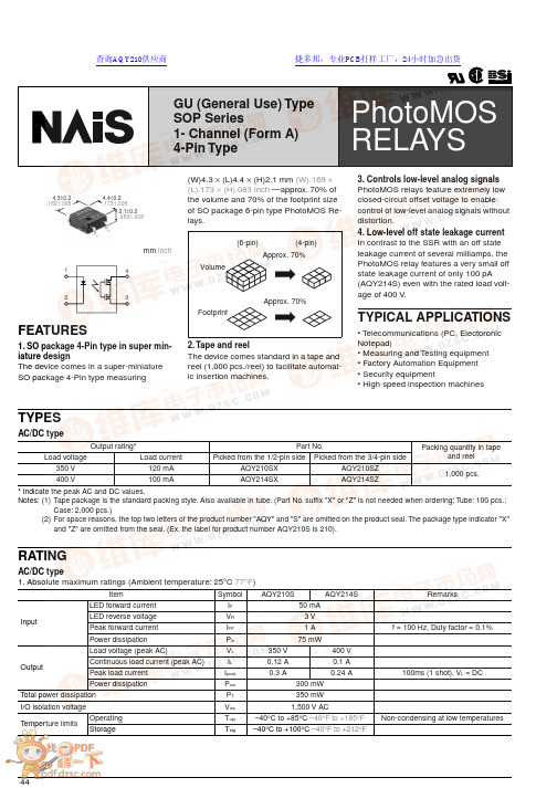
441243GU (General Use) TypeSOP Series1- Channel (Form A) 4-Pin Typemm inch4.4±0.2.173±.0082.1±0.2.083±.0084.3±0.2.169±.008FEATURES1. SO package 4-Pin type in super min-iature designThe device comes in a super-miniature SO package 4-Pin type measuring(W)4.3 × (L)4.4 × (H)2.1 mm (W).169 × (L).173 × (H).083 inch —approx. 70% of the volume and 70% of the footprint size of SO package 6-pin type PhotoMOS Re-lays.2. Tape and reelThe device comes standard in a tape and reel (1,000 pcs./reel) to facilitate automat-ic insertion machines.Volume(4-pin)(6-pin)Approx. 70%FootprintApprox. 70%3. Controls low-level analog signals PhotoMOS relays feature extremely low closed-circuit offset voltage to enable control of low-level analog signals without distortion.4. Low-level off state leakage current In contrast to the SSR with an off state leakage current of several milliamps, the PhotoMOS relay features a very small off state leakage current of only 100 pA (AQY214S) even with the rated load volt-age of 400 V .TYPICAL APPLICATIONS• T elecommunications (PC, Electoronic Notepad)• Measuring and T esting equipment • Factory Automation Equipment • Security equipment• High speed inspection machinesTYPESAC/DC type* Indicate the peak AC and DC values.(1)Tape package is the standard packing style. Also available in tube. (Part No. suffix "X" or "Z" is not needed when ordering; T ube: 100 pcs.;Case: 2,000 pcs.)(2)For space reasons, the top two letters of the product number "AQY" and "S" are omitted on the product seal. The package type indicator "X"and "Z" are omitted from the seal. (Ex. the label for product number AQY210S is 210).Output rating*Part No.Packing quantity in tapeand reelLoad voltageLoad current Picked from the 1/2-pin side Picked from the 3/4-pin side350 V 120 mA AQY210SX AQY210SZ 1,000 pcs.400 V100 mAAQY214SX AQY214SZRATINGAC/DC type1. Absolute maximum ratings (Ambient temperature: 25 ° C 77 ° F )ItemSymbol AQY210SAQY214SRemarksInputLED forward current I F 50 mA LED reverse voltageV R 3 V Peak forward current I FP 1 A f = 100 Hz, Duty factor = 0.1%Power dissipationP in 75 mWOutputLoad voltage (peak AC)V L 350 V 400 V Continuous load current (peak AC)I L 0.12 A 0.1 A Peak load current I peak 0.3 A0.24 A 100ms (1 shot), V L = DCPower dissipationP out 300 mW T otal power dissipation P T 350 mW I/O isolation voltageV iso 1,500 V ACT emperture limitsOperatingTopr –40 ° C to +85 ° C –40 ° F to +185 ° F Non-condensing at low temperaturesStorageTstg–40 ° C to +100 ° C –40 ° F to +212 °FPhotoMOS RELAYS查询AQY210供应商捷多邦,专业PCB打样工厂,24小时加急出货AQY21 r S452. Electrical characteristics (Ambient temperature: 25 ° C 77 ° F )Note: Recommendable LED forward current IF = 5mA. For type of connection, see page 31.*Turn on/T urn off times For Dimensions, see Page 28.s For Schematic and Wiring Diagrams, see Page 31. s For Cautions for Use, see Page 36.ItemSymbol AQY210SAQY214SRemarks InputLED operate currentTypical I Fon 0.9 mA I L = Max.Maximum 3 mA LED turn off current Minimum I Foff 0.4 mA I L = Max.Typical 0.85 mALED dropout voltage Typical V F1.14 V (1.25 V at IF = 50 mA)I F = 5 mA Maximum 1.5 V OutputOn resistanceTypical Ron17 Ω 25 Ω I F = 5 mA IL = Max.Within 1 s on time Maximum 25 Ω35 ΩOff state leakage current Maximum ILeak 1 µ AI F = 0I L = Max.TransfercharacteristicsTurn on time*T ypical T on 0.23 ms0.21 ms I F = 5 mAI L = Max.Maximum 0.5 ms Turn off time*Typical T off 0.04 ms I F = 5 mA I L = Max.Maximum 0.2 ms I/O capacitanceMaximum C iso1.5 pF f = 1 MHz V B = 0Initial I/O isolation resistanceMinimumRiso1,000 M Ω500 V DCInputOutput10%90%REFERENCE DATA1. Load current vs. ambient temperature char-acteristicsAllowable ambient temperature:–40 ° C to +85 ° C–40 ° F to +185 ° F2. On resistance vs. ambient temperature char-acteristicsMeasured portion: between terminals 3 and 4;LED current: 5 mA; Load voltage: Max. (DC);Continuous load current: Max. (DC)3. T urn on time vs. ambient temperature char-acteristicsLED current: 5 mA; Load voltage: Max. (DC);Continuous load current: Max. (DC)60801001202040Ambient temperature, °C L o a d c u r r e n t , m A 01020304050Ambient temperature, °CO n r e s i s t a n c e , Ω1.01.52.50.52.03.0Ambient temperature, °CT u r n o n t i m e , m sAQY21 r S4. Turn off time vs. ambient temperature char-acteristicsLED current: 5 mA; Load voltage: Max. (DC);Continuous load current: Max. (DC)5. LED operate current vs. ambient tempera-ture characteristicsSample: All types; Load voltage: Max. (DC);Continuous load current: Max. (DC)6. LED turn off current vs. ambient temperature characteristicsSample: All types; Load voltage: Max. (DC);Continuous load current: Max. (DC)Ambient temperature, °C T u r n o f f t i m e , m s1234–4050–202040608085Ambient temperature, °C L E D o p e r a t e c u r r e n t , m A1234–4050–202040608085Ambient temperature, °CL E D t u r n o f f c u r r e n t , m A。
Omron B3FS 触摸开关数据手册说明书

B3FSTactile Switch (SMT)Surface-mounting Switches Ideal for High-density Mounting•Tape packing style also available •Allows reflow soldering• 3 actuator heights for design flexibility; Projected plunger versions allow installation of B32-series keytops ■List of ModelsNote:Order in multiples of the minimum order unit. Switches are not sold individually.RoHS CompliantTypePlunger typeHeightOperating force (OF)Plunger colorBagEmbossed taping ModelQuantity per package ModelQuantity per package6 × 6 mm B3FS-1000 models3.1 mm 0.98 N {100 gf}Black B3FS-1000100B3FS-1000P 3,0001.47 N {150 gf}IvoryB3FS-1002B3FS-1002P 2.55 N {260 gf}BlueB3FS-1005B3FS-1005P 4.3 mm0.98 N {100 gf}Black B3FS-1010B3FS-1010P 1,0001.47 N {150 gf}IvoryB3FS-1012B3FS-1012P 2.55 N {260 gf}BlueB3FS-1015B3FS-1015P 7.3 mm0.98 N {100 gf}Black B3FS-1050B3FS-1050P 1.47 N {150 gf}YellowB3FS-1052B3FS-1052P(Flat type)(Flat type)(Projected type)■Ratings/Characteristics■Operating CharacteristicsRatings1 to 50 mA, 5 to 24 VDC (resistive load)Ambient operating temperature -25°C to +70°C at 60%RH max. (with no icing or condensation)Ambient operating humidity 35% to 85% (at +5 to +35°C)Contact form SPST-NOContact resistance 100 m Ω max. (initial value) (rated: 1 mA, 5 VDC)Insulation resistance 100 M Ω min. (at 100 VDC)Dielectric strength 250 VAC, 50/60 Hz for 1 min Bounce time 5 ms max.Vibration resistance Malfunction: 10 to 55 Hz, 1.5-mm double amplitude Shock resistance Destruction: 1,000 m/s 2 {approx. 100G} max. Malfunction: 100 m/s 2 {approx. 10G} max.DurabilityStandard models (0.98 N {100 gf}): 1,000,000 operations min. High-force models (1.47 N {150 gf}): 300,000 operations min. High-force models (2.55 N {260 gf}): 100,000 operations min.Weight B3FS-1000: Approx. 0.2 gB3FS-1000Item0.98 N 1.47 N 2.55 N Operating force (OF)0.98±0.29 N {100±30 gf} 1.47±0.49 N {150±50 gf}2.55±0.69 N {260±70 gf}Releasing force (RF)0.2 N {20 gf} min.0.49 N {50 gf} min.0.49 N {50 gf} min.Pretravel (PT)0.25 +0.2/−0.1 mm■Dimensions (Unit: mm)Note:The numbers used for terminals in the following graphics are indicated in the “Bottom View” diagram below. In this diagram, the Switch is rotated so that the terminals are on the right and left-hand sides, and the OMRON logo appears the right way up.Note:Unless otherwise specified, a tolerance of ±0.4 mm applies to all dimensions. No terminal numbers are indicated on the Switches.■Key Tops B32-series Special Key Tops are available for projected plunger models. Refer to the Datasheet of B32 for details.■PrecautionsBe sure to read the safety precautions common to all Tactile Switches for correct use.。
OMRON光电传感器操作手册
䗝ᢽᖂߚ䖍㓬 ऩջ䖍㓬˖ǃϸջ䖍㓬˖ 䗝ᢽᖂߚࡼᯊ ᖂߚડᑨᯊ䯈 ऩջ䖍㓬ĂõV˖ǃµV˖ǃPV˖ǃPV˖ǃPV˖ ϸջ䖍㓬ĂõV˖ǃµV˖ǃPV˖ǃPV˖ǃPV˖ $7&䫭䇃䕧ߎ˖ ҙ$7&ൟ ᣝ䗮䘧䕧ߎ˖ǃ ফܝㄝ㑻Ͼ䯜ؐП䯈ᯊ䕧ߎ˖ 㞾䆞ᮁ䕧ߎ˖ $7&ࡳ㛑᳝ᬜ˖ǃ $7&ࡳ㛑᮴ᬜ˖ ᮴䆒ᅮ˖ǃ$7&ⱘᓔྟ໘⧚˖ǃ ࡳ⥛䇗䇤ˇ$7&ⱘᓔྟ໘⧚˖
581
䆒ᅮ㒧ᴳৢˈ䖨ಲࠄ ᪡ࠡⱘᰒ冫
581
㟇581
㟇581
408
᳔ᮄѻક䌘᭭䇋ⱏᔩ
᪡㆛⬉ܝӴᛳ఼
ܝ ⬉ Ӵ ᛳ ఼
䆒ᅮࡳ㛑 6(7ᓣ
䗮⫼gᷛ䆚Ẕ⌟ൟ
(;'$ƶ6
ࡳ㛑ߛᤶᯊ᠔ᰒ冫ⱘݙᆍЎߎॖᯊⱘ䆒㕂DŽ ḍ䆒ᅮⱘݙᆍˈࡳ㛑ߛᤶЁৃ㛑Ӯࡴᮄⱘ乍ⳂDŽ
℆581⢊ᗕϟߛᤶᓣᯊ
ঠ䕧ߎ
℆ߛᤶϾ䗮䘧ⱘ䕧ߎݙᆍᯊ
⫼䗨ߚ㉏ ೈ䆒 ҟ㒡 ᡔᴃᣛफ
℆ߛᤶ$7&ࡳ㛑᳝ᬜ᮴ᬜᯊ
ҙ$7&ൟ 䆒ᅮᅠ៤ৢ
ᇚ6(7581ߛᤶᓔ݇䆒Ў 581 DŽ
581
ࡳ㛑ϔ㾜 াࣙᣀҢ䗮⫼ൟᓔྟᮄⱘࡳ㛑DŽᴀࡳ㛑䚼ߚ䇋খ䯙䗮⫼ൟDŽ
83 '2:1
䗮䖛Āߛᤶᰒ冫āࡳ㛑ᬍᰒ冫ᮍ⊩ᯊˈ䗮䖛䬂᪡ᇚ䕙ࡽ᭄ᄫᰒ冫 ߛᤶЎ䯜ؐDŽ
ᡔᴃ㆛ ᪡㆛
䆶⬉䆱800-820-4535
407
ܝ ⬉ Ӵ ᛳ ఼
᪡㆛⬉ܝӴᛳ఼
䗮䖛冫ᬭ䆒ᅮ䯜ؐ 6(7ᓣ
冫ᬭⱘᮍ⊩ˈ᳝བϟಯ辵DŽՓ⫼ᯊ䇋䗝ᢽ᳔ড়䗖ⱘᮍ⊩DŽ 581ᓣϟг㛑䖯㸠冫ᬭ ҙᎹӊ᳝᮴冫ᬭǃ㞾ࡼ冫ᬭ DŽ ᪡ᮍ⊩䇋খ䯙ѻક䰘ᏺⱘĀՓ⫼䇈ᯢкāDŽ ᔧ䕙ࡽ᭄ᄫᰒ冫ߎ⦄Ā29(5āǃĀ/2āǃĀ1($5āᯊˈ㸼冫ߎ䫭DŽ 䇋䞡ᮄ䇗㡖ᑊ䆒ᅮDŽ
欧姆龙 D5F 高精度型光学开关 产品手册
<粘合剂>
陶瓷片以环氧树脂粘合, 后者可能因切割油或热溶剂产生退化。 在 最糟的情况下,陶瓷片可能脱落。陶瓷片可对抗部分切割油或丙 酮。在使用D5F前请检查操作环境。
ܡ䌍 ⬉䆱
䆶⬉䆱
400-820-4535
᳔ᮄֵᙃ
4
购买欧姆龙产品的客户须知
购买时的注意事项
D5F-2B@0
D5F-3C@0
㻤㡆 DC12̚24V 㻤㡆 DC12̚24V ݙ䚼⬉䏃 ON˄ᣝ˅ OFF ҂ ϡ҂ ݙ䚼⬉䏃 100 mAҹϟ 咥㡆䕧ߎ 㪱㡆0V
咥㡆䕧ߎ 㪱㡆0V 100 mAҹϟ
ᣛ冫♃ ˄㑶㡆LED˅
ᣛ冫♃ ˄㑶㡆LED˅
偅ࡼᴚ˖
偅ࡼᴚ˖
ON˄ᣝ˅ OFF
䕧ߎԧㅵ˖ ON ˄䋳䕑˅ OFF ᣛ冫♃˖ (LED)
● 关于使用环境
操作环境对D5F有重要影响。在各种切割油、溶剂或气体环境中使 用D5F之前,请咨询您的欧姆龙代表处。 已对下列12种切割油进行过测试。 如需在其他环境使用, 如其他切 割油、溶剂和气体中,请咨询您的欧姆龙代表处。 切割油 Yushiron油 No. 7 和No. 21 Yushiron切割 UB-75和G-55 EC-50, CN-102, MIC-2, Yushiroken MIC-10和S-52 Emulcut No.10 CosmoCool X106 Cool CH 制造商 Yushiro化学工业有限公司 Yushiro化学工业有限公司 Yushiro化学工业有限公司 Kyodo Yushi 有限公司 Cosmo油有限公司 Idemitsu Kosan有限公司
规格
■ 额定规格
电源电压 输出电流 功耗 漏电流 残留电压 DC12~24V±10%,波纹(p-p):10%以下 100mA以下 30mA以下 0.15mA以下 2V以下
omron E3C小型感测头放大器分式光电开关 说明书

䎱 行
200
Y 150
Y
()
mm
100
X
50
0
0.2
0.4
0.6
0.8
1
䎱行X(m) -50
-100
-150
-200
对射型 E3C-S30T/-S30W
䎱 行 200
Y 150
Y
()
mm
X 100
50
0
200
400
600
800
䎱行X(mm)
-50
-100
-150 -200
扩散反射型
E3C-DS10 (例1)
连接方式
端子台
端子台输入
导线引出
端子台
(标准导线长2m)
重量 (捆包状态) 约200g
约80g
约15g
约100g
容器
ABS
材质
安装金属物 不锈钢
——
铁
聚碳酸酯
——
附属品
连接插口 (PF113A)、 操作说明书
金属安装配件 调整用改锥 警告铃 操作说明书
操作说明书
端子插头* (E99-C) 操作说明书
环境温度
工作时·保存时:各-25~+70℃ (不结冰、结露)
环境湿度
工作时:35~85%RH、保存时:35~95%RH (不结露)
绝缘电阻
20MΩ以上 (DC500V兆欧表)
耐电压
AC500V 50/60Hz 1min
振动 (耐久)
10~55Hz 上下振幅1.5mm X、 Y、 Z各方向 2h
冲击 (耐久)
ᬒ఼ݙ㕂ൟ
50
⬉⑤ݙ㕂ൟ
0
Omron光电开关资料(EE-SX670)
REE-SX470/471/472/473/474/670/671/672/673/674(P)Photomicrosensor with 50mA (PNP)or 100mA (NPN)Switching Capacity that can be Built into EquipmentH Standard,L-shaped,T-shaped,and close mounting models availableH Easy to maintain,plugs into Connector cordset EE-1006H Models available with Light-ON orLight-ON/Dark-ON output configurations H Response frequency as high as 1kHz H Easy operation monitoring with bright LED indicatorHWide operating voltage range (5to24VDC)makes smooth connection of thephotomicrosensor with TTLs,relays,and programmable controllers (PLC)possibleOrdering InformationAppearance Sensing method Slot width Slot depth Output configuration Weight Part number StandardSlot5mm9mmLight-ON Approx.EE-SX470gpp 3.1gEE-SX470PLight-ON/Dark-ON(S t )EE-SX670g /(See note)EE-SX670P L-shaped Light-ON Approx.EE-SX471pgpp 3.0gEE-SX471PLight-ON/Dark-ON(S t )EE-SX671g /(See note)EE-SX671P T-shaped Light-ON Approx.EE-SX472pgpp 2.4gEE-SX472PLight-ON/Dark-ON(S t )EE-SX672g /(See note)EE-SX672P Close-mounting Light-ON Approx.EE-SX473ggpp 2.3gEE-SX473PLight-ON/Dark-ON(S t )EE-SX673g /(See note)EE-SX673P Close-mounting Light-ON Approx.EE-SX474ggpp3.0gEE-SX474PLight-ON/Dark-ON EE-SX674gEE-SX674PNote:The EE-SX67j series models can be used as Light-ON models when the L terminal and positive (+)terminal are short-circuited.To use them as Dark-ON models do not short-circuit these terminals.Connector EE-1001-1can be used for Light-ON operation.EE-SX470/471/472/473/474/670/671/672/673/674(P)EE-SX470/471/472/473/474/670/671/672/673/674(P)2J ACCESSORIESNamePart number Solder connector EE-1001Connector with 2m cable EE-1006Connector holder for EE-1006EE-1006ASpecificationsJ RATINGSItem Standard L-shaped T-shaped Close-mounting Output typeNPN output EE-SX470EE-SX670EE-SX471EE-SX671EE-SX472EE-SX672EE-SX473,EE-SX474EE-SX673,EE-SX674PNP outputEE-SX470P EE-SX670PEE-SX471P EE-SX671PEE-SX472P EE-SX672PEE-SX473P ,EE-SX474P EE-SX673P ,EE-SX474PSupply voltage 5to 24VDC ±10%,ripple (p-p):10%max.Current consumption NPN models:35mA max.,PNP models:30mA max.Standard reference object Opaque:0.8x 2mm Differential distance 0.025mmControl outputNPN open collector output models:At 5to 24VDC:100mA load current (l c )with a residual voltage of 0.8V max.When driving TTL:40mA load current (l c )with a residual voltage of 0.4V max.PNP open collector output models:At 5to 24VDC:50mA load current (l c )with a residual voltage of 1.3V max.Indicator note 1.)Without detectingobject ON (See ote )With detecting objectOFFResponse frequency (See note 2.)1kHz max.(3kHz typ.)Light source GaAs infrared LED with a peak wavelength of 940nm ReceiverSi phototransistor with a sensing wavelength of 850nm max.Connecting methodEE-1001/1006Connectors;soldering terminals/cordsetNote:1.The indicator is GaP red LED (peak emission wavelength:690nm).2.The response frequency was measured by detecting the following disks rotating.Disk2.1mm1mm1mmt =0.2mmEE-SX470/471/472/473/474/670/671/672/673/674(P)EE-SX470/471/472/473/474/670/671/672/673/674(P)3J CHARACTERISTICSAmbient illumination (See note 1.)Fluorescent light:1,000ℓx max.Ambient temperature Operating -25°C to 55°C (-13°F to 131°F)p Storage -30°C to 80°C (-22°F to 176°F)Ambient humidity Operating 5%to 85%y Storage5%to 95%Vibration resistance Destruction:20to 2,000Hz,(with a peak acceleration of 10G),1.5-mm doubleamplitude for 2hrs (with 4-minute cycles)each in X,Y ,and Z directions Shock resistanceDestruction:500m/s 2(approx.50G)for 3times each in X,Y ,and Z directions Soldering heat resistance (See note 2.)260°±5°C when the portion between the tip of the terminals and the position 1.5mm from the terminal base is dipped into the solder for 10±1seconds Degree of protection IEC 60529,IP50MaterialsCase Polybutylene teraphthalate (PBT)CoverPolycarbonate (PC)Emitter/Receiver Polycarbonate (PC)Note:1.The ambient luminance is measured on the surface of the receiver.2.This conforms to MIL-STD-750-2031-1.Engineering DataJ SENSING POSITION CHARACTERISTICS (TYPICAL)Tr ONTr OFFDark-ON modeDistance d (mm)Tr ONTr OFFDark-ON modeDistance d (mm)J REPEATED SENSING POSITION CHARACTERISTICS (TYPICAL)No.of repetitions:20at V cc =12V Distance d (mm)O u t p u t l e v e l t r a n s i s t o rn d1=0.002mm n d2=0.004mm n d3=0.005mm n d4=0.02mm n d5=0.04mmddEE-SX470/471/472/473/474/670/671/672/673/674(P)EE-SX470/471/472/473/474/670/671/672/673/674(P)4OperationEE-SX470/471/472/473/474/670/671/672/673/674(P)EE-SX470/471/472/473/474/670/671/672/673/674(P)5DimensionsUnit:mm (inch)J EE-SX470(P),EE-SX670(P)Two,3.2dia.holesFour,R1Optical axis(1)(2)(3)(4)Two,3.8dia.holesIndicator windowTerminal Arrangement (1)(2)(3)(4)V CCL OUTL (See Note.)OUTPUT GND (0V)25.4(1.00)19(0.75)6.95(0.27)6.4(0.25)13.4(0.53)0.8(0.03)5(0.20)19(0.75)2(0.08)13.8(0.54)0.3(0.01)0.7(0.03)9(0.35)2.54(0.10)13.2(0.52)5.5(0.22)3.8(0.15)6.2(0.24)Note:L Terminal needs noconnection for all EE-SX47j series sensors.J EE-SX471(P),EE-SX671(P)Four,R1.0Indicator windowOptical axisTwo,3.2dia.holesFour,R2(1)(2)(3)(4)Note:L Terminal needs no connection for all EE-SX47j series sensors.Terminal Arrangement(1)(2)(3)(4)V CCL OUTL (See Note.)OUTPUT GND (0V)26.2(1.03)3.0(0.12)3.2(0.13)19.0(0.75)6.2(0.24)9.0(0.35)5.0(0.20)14.5(0.57)7.2(0.28)6.20(0.24)13.4(0.53)3.8(0.15)2.54(0.10)13.0(0.51)9.0(0.35)2.1(0.08) 6.35(0.25)15.5(0.61)2(0.08)0.8(0.03)3.6(0.14)7.2(0.28)13.0(0.51)13.4(0.53)19.0(0.75)0.7(0.03)0.3(0.01)0.6(0.02)6.95(0.27)8.3(0.33)EE-SX470/471/472/473/474/670/671/672/673/674(P)EE-SX470/471/472/473/474/670/671/672/673/674(P)6J EE-SX472(P),EE-SX672(P)Indicator window operation (back)Optical axis4-R1.64-R1.0Terminal Arrangement (1)(2)(3)(4)V CCL OUTL (See Note.)OUTPUT GND (0V)13.7(0.54)2.54(0.10)3.0(0.12)2.9(0.11)3.8(0.15)0.2(0.01)6.2(0.24)5.0(0.20)22.2(0.87)13.4(0.53)9.0(0.35)26.0(1.02)6.4(0.25)12.6(0.50)4.3(0.17)13(0.51)0.8(0.03)19.0(0.75)6.3(0.25)2(0.08)0.7(0.03)6.2(0.24)0.3(0.01)0.1(0.004)0.1(0.004)Note:L Terminal needs no connection for all EE-SX47j series sensors.J EE-SX473(P),EE-SX673(P)Two,R1Two,3.2dia.holes(1)(2)(3)(4)Optical axis Indicator windowTerminal Arrangement (1)(2)(3)(4)V CCL OUTL (See Note.)OUTPUT GND (0V)2.54(0.10)3.8(0.15)6.2(0.24)5(0.20)22.2(0.87)13.4(0.53)9(0.35)0.8(0.03)2(0.08)0.7(0.03)0.3(0.01)6.65(0.26)7(0.28)14.4(0.57)2.8(0.11)4.9(0.19)6.3(0.25)12.8(0.50)3.5(0.14)Note:L Terminal needs no connection for all EE-SX47j series sensors.EE-SX470/471/472/473/474/670/671/672/673/674(P)EE-SX470/471/472/473/474/670/671/672/673/674(P)7J EE-SX474(P),EE-SX674(P)2--R11234Optical Axis Optical Axis MarkTwo 3.5dia holes Light IndicatorNote:L Terminal needs no connection for all EE-SX47j series sensors.Terminal Arrangement (1)(2)(3)(4)V CCL OUTL (See Note.)OUTPUT GND (0V)7(0.28) 2.2(0.09)0.3(0.01)2.1(0.08)0.6(0.02)0.7(0.03)13.6(0.54)9.3(0.37)2.9(0.11)5(0.20)13.0(0.51)2.54(0.10)3(0.12)3.8(0.15)6.2(0.24)21.5(0.85)0.8(0.03)7(0.28)6.2(0.24)2.6(0.10)15.5(0.61)0.1(0.004)JEE-1001SOLDER CONNECTORJ EE-SX67j (P)WITH EE-1001CONNECTOR2.54±0.152.9±113.0(0.51)6.0(0.24)10.8(0.43)22.2(0.87)0.6(0.02)6.0(0.24)10.8(0.43)4.0(0.16)J EE-1006CONNECTOR WITH CABLE(1)(2)(3)(4)Note:Older standard colors are shown inparentheses.Connector comes with a 2-m attached cable.Terminal Arrangement --IEC Colors (1)(2)(3)(4)Brown (Red)Pink (Yellow)Black (White)Blue (Black)LOUTVCC OUTPUT L GND (O V)2.54(0.10)0.6(0.02)11.8(0.46)25(0.98)2,000(78.74)20(0.79)16.2(0.64)5.3(0.21)15(0.59)EE-SX470/471/472/473/474/670/671/672/673/674(P)EE-SX470/471/472/473/474/670/671/672/673/674(P)8J EE-1006A CONNECTOR HOLDERR3Four,R2Four,R1.6(R1)21.9(0.86)25.2(0.99) 1.2(0.05)5.5(0.22)2(0.08)15(0.59)19.4(0.76)10.2(0.40)3(0.12)2.1(0.08)3.6(0.14)3.4(0.13)3.2(0.13)12(0.47)19(0.75)3(0.12)PrecautionsRefer to the the Technical Information Section for general precautions.The sensing window is made of a polycarbonate resin which withstands chloride solvents and strong acids but is soluble in strong alkali,aromatic hydrocarbons,and aliphatic hydrocarbonate chloride solvents.The casing material uses a PBT resin which withstandschemicals and oil but is soluble in strong acid or alkali solvents.The temperature of the terminals at the time of soldering must not exceed the following:Item Temperature Permissible time Remarks Dip260°C10secThe portion be-tween the base of the terminals and 15Iron350°C3secthe position 1.5mm from the ter-minal base must not be soldered.The terminal base uses a polycarbonate resin,which could be deformed by excessive soldering heat.Cat.No.GC APMS-109/02Specifications subject to change without notice.Printed in U.S.A.OMRON ELECTRONICS LLCOne East Commerce Drive Schaumburg,IL 60173NOTE:DIMENSIONS SHOWN ARE IN MILLIMETERS.To convert millimeters to inches divide by 25.4.1-800-55-OMRONOMRON CANADA,INC.885Milner Avenue416-286-6465ROMRON ON--LINEGlobal -- USA --/oei Canada --/ociToronto,Ontario M1B 5V8。
OMRON光电开关调节与设定
«电工技术» 2002年1期 OMRON 光电传感器 调节与设定重庆大学电气工程学院 廖常初[摘要]以OMRON的光电传感器为例,介绍了光电传感器常见的调节和设定方法。
关键词 传感器 光电 调节为了保证光电传感器功能的实现,降低调试难度,减少调试时间,现代光电传感器设置了很多调节功能,给使用者带来了极大的方便。
1.光轴的调节OMRON公司比较典型的对射式光纤传感器的放大器E3X-NT21如图1所示,图2使它的输出电路。
调节光轴时,将模式(MODE)开关置于TEACH(示教)位置,可执行特殊闪动功能。
如发光光纤与受光光纤的尖端未对齐,或光轴未对正,使受光亮度低于峰值的10%时,投光光纤尖端的指示灯不断闪动,且蜂鸣器发出响声。
将光纤光轴对证对齐后,该指示灯停止闪动,处于亮灯状态,调节结束。
在光轴矫正前、校正中按下示教按钮,特殊闪动功能消失。
2.最大灵敏度设定有示教功能的传感器首先应调节最大灵敏度。
将发光光纤和受光光纤放在检出距离之内。
将放大器上的模式设定开关切换到TEACH一侧,调整对齐发光光纤和受光光纤的光轴。
按下示教按钮3s以上,示教指示灯三红变绿。
内部的蜂鸣器在红灯时响一声,绿灯亮时连续响。
松开示教按钮后,蜂鸣器停止发声。
将模式切换开关切换到RUN位置,最大灵敏度设定结束。
示教指示灯熄灭。
设定最大灵敏度时,与光纤间的距离,是入光还是遮光无关。
用动作模式切换开关设定希望的逻辑输出。
若开光置于L.ON(Light ON),受光时输出为ON,若置于D.ON( Dark ON),遮光时输出为ON。
3.无工作示教示教(TEACH)功能用来检测背景光的强度或光泽度,以消除背景光的影响,使传感器能正确分辨出被检测物的有无,或分辨光量、光泽的变化。
无工件示教时,将发光光纤和受光光纤放在检出距离之内,放大器上的模式设定开关切换到TEACH一侧,调整对齐发光光纤和受光光纤的光轴。
无被检测物时按下示教按钮0.5~2.5s,示教指示灯红灯亮,内部的蜂鸣器响一声。
omron - ee-sx1088 光电开关 (透射式) 说明书
52EE-SX1088 Photomicrosensor (Transmissive)■DimensionsNote:All units are in millimeters unless otherwise indicated.■Features•General-purpose model with a 3.4-mm-wide slot.•Mounts to PCBs or connects to connectors.•High resolution with a 0.5-mm-wide aperture.•OMRON’s XK8-series Connectors can be connected without sol-dering. Contact your OMRON representative for information on obtaining XK8-series Connectors.■Absolute Maximum Ratings (Ta =25°C)Note:1.Refer to the temperature rating chart if the ambient temper-ature exceeds 25°C.2.The pulse width is 10 μs maximum with a frequency of 100Hz.plete soldering within 10 seconds.■Electrical and Optical Characteristics (Ta = 25°C)Internal CircuitCETerminal No. Name A Anode K Cathode C Collector EEmitterDimensions Tolerance 3 mm max.±0.33 < mm ≤ 6 ±0.3756 < mm ≤ 10 ±0.4510 < mm ≤ 18 ±0.5518 < mm ≤ 30±0.65Two, R1Two, 3.2±0.2 dia. holesTwo, C2Four, C0.3Four, 0.25Four, 0.5(Optical axis)Cross section BBCross section AA25±0.219±0.150.5±0.16.5±0.10.5±0.18.4±0.13±0.45±0.26±0.22.5±0.17.2±0.210±0.2Unless otherwise specified, the tolerances are as shown below.ItemSymbol Rated value Emitter Forward current I F 50 mA(see note 1)Pulse forward cur-rentI FP 1 A(see note 2)Reverse voltageV R 4 V DetectorCollector–Emitter voltageV CEO 30 V Emitter–Collector voltageV ECO ---Collector current I C 20 mA Collector dissipa-tionP C 100 mW (see note 1)Ambient tem-peratureOperating Topr –25°C to 85°C StorageTstg –30°C to 100°C Soldering temperatureTsol260°C(see note 3)ItemSymbolValueConditionEmitterForward voltage V F 1.2 V typ., 1.5 V max.I F = 30 mA Reverse currentI R 0.01 μA typ., 10 μA max.V R = 4 V Peak emission wavelengthλP 940 nm typ.I F = 20 mADetectorLight current I L 0.5 mA min., 14 mA max.I F = 20 mA, V CE = 10 V Dark current I D 2 nA typ., 200 nA max.V CE = 10 V, 0 l x Leakage currentI LEAK ------Collector–Emitter saturated volt-ageV CE (sat)0.15 V typ., 0.4 V max.I F = 20 mA, I L = 0.1 mA Peak spectral sensitivity wave-lengthλP 850 nm typ.V CE = 10 VRising time tr 4 μs typ.V CC = 5 V, R L = 100 Ω, I L = 5 mA Falling timetf4 μs typ.V CC = 5 V, R L = 100 Ω, I L = 5 mABe sure to read Precautions on page 25.EE-SX1088 Photomicrosensor (Transmissive) 53■Engineering DataDissipation Temperature RatingVoltage Characteristics (Typical)Characteristics (Typical)Light Current vs. Collector −Emitter Voltage Characteristics (Typical)Dark Current vs. Ambient Temperature Characteristics (Typical)Distance d (mm)Input OutputInputOutput90 %10 %(Center of optical axis)Sensing Position Characteristics (Typical)Response Time Measurement CircuitAmbient temperature T a (°C)C o l l e c t o r d i s s i p a t i o n P C (m W )Forward voltage V F (V)Forward current I F (mA)L i g h t c u r r e n t I L (m A )Collector −Emitter voltage V CE (V)L i g h t c u r r e n t I L (m A )Ambient temperature Ta (°C)Load resistance R L (k Ω)I F P CT a = −30°C T a = 25°C T a = 70°CT a = 25°C V CE = 10 VI F = 40 mA I F = 30 mA I F = 20 mA I F = 10 mAT a = 25°CV CE = 10 V 0 l xI F = 20 mA V CE = 5 VI F = 20 mA V CE = 10 V T a = 25°CV CC = 5 V T a = 25°CR e s p o n s e t i m e t r , t f (μs )R e l a t i v e l i g h t c u r r e n t I L (%)D a r k c u r r e n t I D (n A )I F = 50 mA Ambient temperature Ta (°C)Relative Light Current vs. Ambi-ent Temperature Characteristics (Typical)Response Time vs. Load Resist-ance Characteristics (Typical)Distance d (mm)Sensing Position Characteristics (Typical)R e l a t i v e l i g h t c u r r e n t I L (%)100806040200−1.5−2.0−1.0−0.500.51.01.52.0120dI F = 20 mA V CE = 10 V T a = 25°C(C e n t e r o f o p t i c a l a x i s )。
欧姆龙光电开关说明书
欧姆龙光电开关说明书欧姆龙光电开关说明书欧姆龙光电开关是一种智能化的电子元件,其主要作用是通过光电原理进行物体检测和位置控制。
本说明书将详细介绍欧姆龙光电开关的特点、工作原理、应用场景及使用方法。
一、特点:1.欧姆龙光电开关是一种高精度、高稳定性、可靠性极强的电子元件。
2.具有光电隔离、噪声抑制、防护等多种功能,适用于各种复杂环境。
3.采用LED和光敏二极管作为光电转换元件,光电效率高,响应速度快。
4.外部封装材料采用耐磨损、耐腐蚀等工程塑料,有很好的耐用性。
二、工作原理:欧姆龙光电开关通过内部光电器件产生光束,当光束遇到物体时,被物体反射后重新聚焦到另一端的光电器件中,从而完成物体的检测。
欧姆龙光电开关具有光电隔离功能,内部电路和外部电路之间采用光耦隔离,有效地防止外部杂音对内部电路造成的干扰。
三、应用场景:欧姆龙光电开关广泛应用于机械、自动化控制、制造业等领域,主要用于非接触式物体检测、位置控制、安全门的监测等方面。
1.非接触式物体检测:无需接触被检测物体,避免了传统机械开关导致的松动、震动等问题,可以检测各种形状、大小、材质的物体。
2.位置控制:通过欧姆龙光电开关的探头来确认物体的位置,可以实现高精度的位置控制。
3.安全门监测:应用于工业机器人、机床等设备的安全门监测,如果关门后开关没有断开,则不允许机器运转,保证工作安全。
四、使用方法:欧姆龙光电开关使用便捷,安装简单。
1.安装:根据欧姆龙光电开关的不同型号和尺寸进行选型,将开关固定在合适的位置,光电探头对准被检测物体即可。
2.电路连接:按照说明书的接线图进行连接,注意接口与电压等参数的匹配。
3.调试:路电线接好后进行检测,根据不同的检测需求进行参数调整,使光电开关的工作符合工作要求。
总之,欧姆龙光电开关是一种高精度、高稳定、安全可靠的电子元件,在工业、汽车、航空等领域中得到了广泛的应用。
相信在未来的发展中,欧姆龙光电开关会继续引领各领域的技术发展和应用进步,推动人类社会的不断发展。
- 1、下载文档前请自行甄别文档内容的完整性,平台不提供额外的编辑、内容补充、找答案等附加服务。
- 2、"仅部分预览"的文档,不可在线预览部分如存在完整性等问题,可反馈申请退款(可完整预览的文档不适用该条件!)。
- 3、如文档侵犯您的权益,请联系客服反馈,我们会尽快为您处理(人工客服工作时间:9:00-18:30)。
欧姆龙光电开关手册
接近开关是一种无需与运动部件进行机械直接接触而可以操作的位置开关,当物体接近开关的感应面到动作距离时,不需要机械接触及施加任何压力即可使开关动作,从而驱动直流电器或给计算机(plc)装置提供控制指令。
接近开关是种开关型传感器(即无触点开关),它既有行程开关、微动开关的特性,同时具有传感性能,且动作可靠,性能稳定,频率响应快,应用寿命长,抗干扰能力强等、并具有防水、防震、耐腐蚀等特点。
产品有电感式、电容式、霍尔式、交、直流型。
接近开关又称无触点接近开关,是理想的电子开关量传感器。
当金属检测体接近开关的感应区域,开关就能无接触,无压力、无火花、迅速发出电气指令,准确反应出运动机构的位置和行程,即使用于一般的行程控制,其定位精度、操作频率、使用寿命、安装调整的方便性和对恶劣环境的适用能力,是一般机械式行程开关所不能相比的。
它广泛地应用于机床、冶金、化工、轻纺和印刷等行业。
在自动控制系统中可作为限位、计数、定位控制和自动保护环节等。
欧姆龙光电开关手册。