阿特拉斯空压机面板中英文对照表
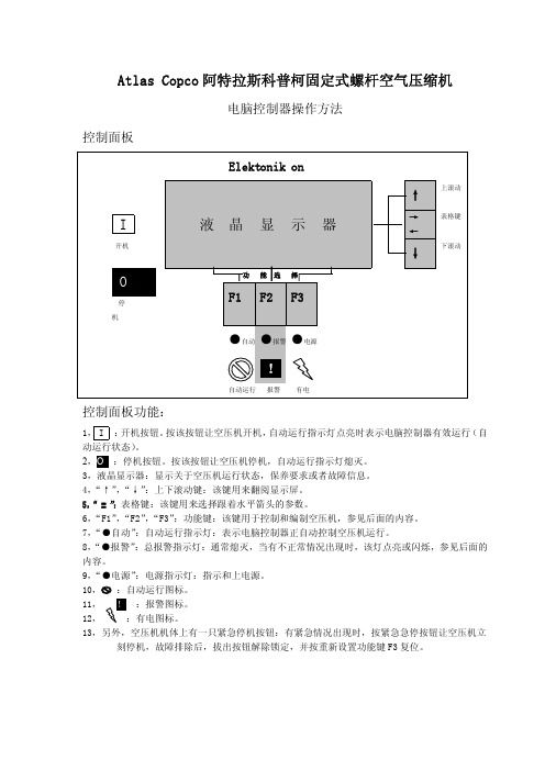
阿特拉斯空压机控制面板操作说明

阿特拉斯空压机控制面板操作说明1--启动按钮 (此按钮可用来启动压缩机。
指示灯(8)点亮,表示EⅡ电脑控制器正在运行。
) 2—显示屏 (显示有关压缩机的工作状况,保养及故障信息)3—滚动键 (此键可用向上或向下滚动显示屏)4--制表位键TAB (按此键,可以选择水平箭头标示的参数,只能修改后面有水平箭头的参数.)5—功能键 (功能键可以用来控制和设定压缩机)6--电源指示灯 (指明已接通电源)7—综合报警指示灯(如果存在报警,保养报警,则该指示灯会亮起)8—自动运行指示灯(指明电脑控制器正在自动运行)9---停机按钮(按下此按钮,可以停止运行压缩机.(8)会熄灭。
在卸载情况下运行30秒后,压缩机将停止运行)S3—紧急停机按钮(按此按钮,可以在紧急情况下立即停止压缩机,排除故障后拔出按钮以解除锁定。
)开机前1、检查油位。
油位指针必须指在绿色区域的上部或高于该区域。
2、如果空气过滤器保养指示器的彩色部分完全显示出来,更换空气过滤器芯,参考使用说明书复位保养指示器和保养报警时钟。
开机1、合上电源。
检查电源指示灯(6)是否点亮。
2、打开空气出气阀。
3、关闭冷凝液排污阀。
4、按开机按钮I。
空压机开始运行,自动运行指示灯(8)点亮,开机后10秒,空压机开始加载运行。
在运行中1、经常检查油位,在加载中,指针必须位于绿色区域。
2、如果指示灯(8)点亮,电脑控制器正自动控制压缩机的加载,卸载,停机和重新启动。
3、经常检查显示屏(2):空压机的运行状态通过图标显示在显示屏上。
4、如果报警指示灯(7)点亮或闪烁,请排除故障,参考使用说明书。
如果需保养,停机并执行保养措施,参考使用说明书。
停机1、按停机按钮O。
指示灯(8)熄灭。
空压机大约卸载运行30秒后停机。
2、在紧急情况下停机,按控制面板旁的红色紧急停机按钮,报警指示灯(7)闪烁。
在重新开机前拨出按钮并按重新设置键解除锁定。
3、关闭空气出气阀并切断电源。
4、打开冷凝液排污阀。
完整版阿特拉斯空压机操作说明
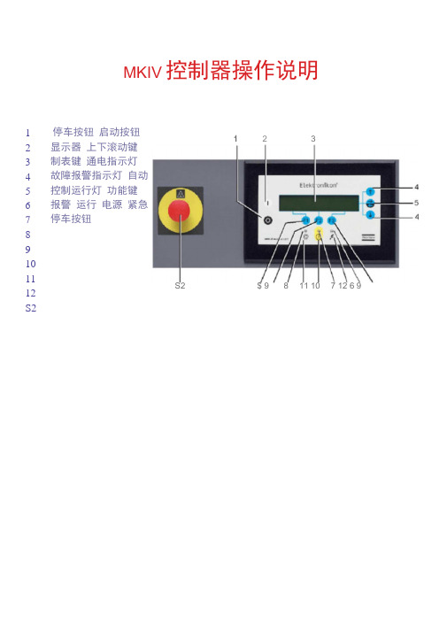
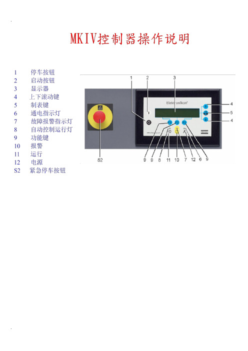
MKIV 控制器操作说明停车按钮 启动按钮 显示器 上下滚动键 制表键 通电指示灯 故障报警指示灯 自动控制运行灯 功能键 报警 运行 电源 紧急停车按钮 123456789101112S2 1 2 3 S2 $ 9 8 11 10 7 12 6 91显示屏-键1典型显示图显示器有四行:i前三行:一一显示屏显示传感器的名称和实际的读数。
――测量值的单位和传感器的实际读数。
――关于空压机运行的信息(空压机停机,等等),保养要求(比如油过滤器和空气过滤器)或者是故障信息(比如故障停机)2滚动键(TJ):这些滚动键标有垂直的箭头,允许滚动显示屏。
——只要在显示屏的最右边的位置上有一个指向下面的箭头,其对应的滚动键就可以用来查阅下面的内容3 表格键( = ):该键标有两个水平箭头,允许操作者选择标有水平箭头的参数。
只有后面跟着指向右面的箭头的参数才可以修改,3 功能键(F1/F2/F3):——用于查阅或编制设定值,——复位电机过载,故障停机或保养信息,或紧急停机, ——查看电脑控制器收集到的所有参数,――(F1/F2/F3)所对应的功能根据显示的菜单变化而变化,它们的实际功能显示在显示屏的底部,刚好在相应的功能键的上面。
最常用的功能中英文对应如下:Automatically Loaded自动加载Automatic Operation自行运行matically Loaded自动卸载Locally controlled本地控制Remote controlled遥控控制Manual Operation手动运行Manual Unloaded手动卸载Unioad卸载Running hours运行时间Loading hours加载时间Main Screen主显示屏Shutdown故障停机Compressor Outlet压缩机排气口Show More更多Add增加指令用来增加空压机的自动启动/停机(日期)Back返回指令返回到的选择或菜单Cancel取消当设定参数有误时.用来取消已设定的数dleete删除用来删除空压机的自动启动/停机时间Help帮助帮助寻找Atlas Copco的内部地址Limits上下限显示允许设定的上下极限数据Load负载手动操作空压机负载Main screen回到主目录从任一画面回到主目录Menu菜单Modify修改修改设定参数Status Data状态参数Shutdown故障停机Shutdown Warning故障停机报警Motor overload电机过载Running Hours运行时间Program编写输入将新的设定数据编写输入Reset重新设定重新设定计时器及信息,定时器或复位Rtrn回归回归到前一页或前一目录Maximum最大值Shutdown Maximum故障停机最大设置值Reset复位All protection functions are OK 所有保护功能都正常 Protection Function activated 保护功能激活Related protection settings 相关的保护功能设置Element 主机头排气口空气过滤器上的压降 无需保养 需要保养 油过滤器 有关的保养设置值 保养 最大设置值 可编制设置值 信号延迟 定时器没有激活 配置 额外的 找寻调节器的构造模式 寻找关于安装的电脑控制器的信息 列出已输入的开机 / 停机指令(日 /小时) 快速浏览压缩机的运行状态; 选择子菜单或阅读显示屏上显示的选项的详细情况 2 开机作业1 开机前检查事项(1) 检查冷凝循环水压力(2) 检查机器内油位是否正常(橙色为高位,运行绿区为正常,红区为低位需补专用油)有没有油 的跑、冒、滴、漏的现象;(3) 供气管道的手动阀门都在开启状态(4) 机器排污阀门都在关闭状态(5) 过滤器的排污有自动排污阀的阀门应开启(6) 不带自动排污阀的阀门应关闭;(7)电源送到空压机后,检查空压机本身的电脑控制显示器内的状态参数,压力,温度都为正常,与实际相符,没有报警。
阿特拉斯空压机面板操作说明

阿特拉斯空压机控制面板操作说明发布日期:2010-12-19 22:16:37阿特拉斯空压机控制面板操作说明(阿特拉斯空压机电脑板,阿特拉斯空压机控制面板)1--启动按钮(此按钮可用来启动压缩机。
指示灯(8)点亮,表示EⅡ电脑控制器正在运行。
)2—显示屏(显示有关压缩机的工作状况,保养及故障信息)3—滚动键(此键可用向上或向下滚动显示屏)4--制表位键TAB (按此键,可以选择水平箭头标示的参数,只能修改后面有水平箭头的参数.)5—功能键(功能键可以用来控制和设定压缩机)6--电源指示灯(指明已接通电源)7—综合报警指示灯(如果存在报警,保养报警,则该指示灯会亮起)8—自动运行指示灯(指明电脑控制器正在自动运行)9---停机按钮(按下此按钮,可以停止运行压缩机.(8)会熄灭。
在卸载情况下运行30秒后,压缩机将停止运行)S3—紧急停机按钮(按此按钮,可以在紧急情况下立即停止压缩机,排除故障后拔出按钮以解除锁定。
)开机前1、检查油位。
油位指针必须指在绿色区域的上部或高于该区域。
2、如果空气过滤器保养指示器的彩色部分完全显示出来,更换空气过滤器芯,参考使用说明书复位保养指示器和保养报警时钟。
开机1、合上电源。
检查电源指示灯(6)是否点亮。
2、打开空气出气阀。
3、关闭冷凝液排污阀。
4、按开机按钮I。
空压机开始运行,自动运行指示灯(8)点亮,开机后10秒,空压机开始加载运行。
在运行中1、经常检查油位,在加载中,指针必须位于绿色区域。
2、如果指示灯(8)点亮,电脑控制器正自动控制压缩机的加载,卸载,停机和重新启动。
3、经常检查显示屏(2):空压机的运行状态通过图标显示在显示屏上。
4、如果报警指示灯(7)点亮或闪烁,请排除故障,参考使用说明书。
如果需保养,停机并执行保养措施,参考使用说明书。
5、停机1、按停机按钮O。
指示灯(8)熄灭。
空压机大约卸载运行30秒后停机。
2、在紧急情况下停机,按控制面板旁的红色紧急停机按钮,报警指示灯(7)闪烁。
在 阿特拉斯空压机操作说明 中的 WPS文档
→ ← 按 表 格 键
Protections (保护) Service Plan (保养计划) Menu (菜单)
按滚动键 Parameters (参数) Protections (保护) Service Plan (保养计划) Menu (菜单)
按滚动键↓ ↑ 按 表 → 格 键 ↓ → ← Compressor Outlet5.4bar (压缩机出口压力) Dp Oil Separator 1.1bar (油分离器数据) Dp Air Filter -0.011bar ↓ 按 滚 动 键 → -喷油压力-空压机出气压力 -机头 1 出口压力-机头 2 出口压力 -冷却介质温度-油分离器-紧急停机 -冷干机露点温度-冷却水进水温度 -冷却出水温度-压力带 1 开/2 关 -冷凝液温度-远程开机/停机 -远程加载/卸载-远程压力传感器 -电机过载-高压冷干机-冷干机过载 -启动器反馈触点 Service Timer (保养时间) → → ← ↓ 按 表 格 键 按滚动键↓ Service Plan (保养计划) Clock Function (时钟功能) Configuration (配置) Menu (菜单) 按滚动键↓ Service Plan (保养计划) Clock Function ↑ 按 表 格 Time (时间) Date 03/05/01 10:54 按 滚 -使用的语言 -温度单位 -水平单位 -压力单位 -振动单位 -使用的压力带 ↓ → → ← 按 表 格 键 Menu (菜单) Modify (修改) Delete (删除) ↑ Clock Function (时钟功能) Not Activated (没激活) → Menu (菜单) Running hours (运转时间) 130 hrs ↓ →
各种螺杆空压机铭牌识别及相关英文熟悉

铭牌识别及相关英文熟悉
一、 ATLAS COPCO阿特拉斯.柯普科
机组系列号分布图
G系列机型认识
G A 132 W (P C SP FF)-7.5
机组输出最大工作压力 全性能机组(内置干燥机)
仪表标准箱式机组
经济型机组
标准型机组 水பைடு நூலகம்(不标代表风冷)
马达额定输入轴功率
单级压缩(R代表双级压缩) 有油机组
UP系列机型认识
UP 5 - 11 -10
机组输出最大工作压力(单位为pa) 马达额定输入轴功率(单位KW) 表示频率50HZ UPTAS系列机组
UNI系列机型认识
UNI-15-7
机组输出最大工作压力(单位为pa)
马达额定输入轴功率(单位HP)
UNIGY系列变频机组
四、 COMPAIR/DEMAG康普艾/德马格
L系列机型认识
L 30 G -08 A
风冷(W为水冷) 机组输出最大工作压力(单位为Mpa) 驱动方式 直联式 马达额定输入轴功率(单位KW) 有油螺杆机组
D系列机型认识
D 75-08 W
水冷(A为风冷) 机组输出最大工作压力(单位为Mpa) 马达额定输入轴功率(单位KW) 无油螺杆机组
HV系列机型认识
ARP: AII:
比较老的机组(1990年以前生产);
GA90以下原装进口(不包括GA90);
GA90以上原装(包括GA90、所有无油机组); 无锡组装:机组核心部分为进口,2000年以前;生产 的尾数为6位2000年以后生产的尾数为10位。 2005年以后无锡组装。
AIF:
WAC: WUX:
二、 SULLAIR寿力
排气压力为0.86Mpa(XF=0.69Mpa/HP=0.98Mpa/XP=1.18Mpa
阿特拉斯空压机操作说明
1典型显示图
显示器有四行:1 前三行:——显示屏显示传感器的名称和实际的读数。
——测量值的单位和传感器的实际读数。
——关于空压机运行的信息(空压机停机,等等),保养要求(比如油过滤器和空气过滤器)或者是故障信息(比如故障停机)
2滚动键(↑↓):——这些滚动键标有垂直的箭头,允许滚动显示屏。
Compressor Outlet压缩机排气口
Show More更多
Add增加指令用来增加空压机的自动启动/停机(日期)
Back返回指令返回到的选择或菜单
Cancel取消当设定参数有误时.用来取消已设定的数
dleete删除用来删除空压机的自动启动/停机时间
Help帮助帮助寻找Atlas Copco的内部地址
Xtra额外的找寻调节器的构造模式
Extra寻找关于安装的电脑控制器的信息
List列出已输入的开机/停机指令(日/小时)
Show More快速浏览压缩机的运行状态;
Sele2开机作业
1开机前检查事项
(1)检查冷凝循环水压力
(2)检查机器内油位是否正常(橙色为高位,运行绿区为正常,红区为低位需补专用油)有没有油的跑、冒、滴、漏的现象;
(3)供气管道的手动阀门都在开启状态
(4)机器排污阀门都在关闭状态
(5)过滤器的排污有自动排污阀的阀门应开启
(6)不带自动排污阀的阀门应关闭;
(7)电源送到空压机后,检查空压机本身的电脑控制显示器内的状态参数,压力,温度都为正常,与实际相符,没有报警。报警消除后才可开机;
2开机步骤
(1)检查水路/气路/油路,是否有泄漏,检查高压是否具备合闸条件
——查看电脑控制器收集到的所有参数,
——(F1/F2/F3)所对应的功能根据显示的菜单变化而变化,它们的实际功能显示在显示屏的底部,刚好在相应的功能键的上面。
阿特拉斯面板操作手册(英文版)
Atlas Copco Stationary Air CompressorsGA5-7-11C-11-15-18-22-30C-30-37-45-55C-55-75-90C and GA30 W-37 W-45 W-55C W-55 W-75 W-90C WWith Elektronikon I or Elektronikon II regulatorUser manual for Elektronikon® I and II regulatorsCompressor type:. . . . . . . . . . . . . . . . . . . . . . . . . . . . . . . . . . . . . . . . Unit serial No. compressor:. . . . . . . . . . . . . . . . . . . . . . . . . . . . . . . . . . . . Air dryer type:. . . . . . . . . . . . . . . . . . . . . . . . . . . . . . . . . . . . . . . . . . Unit serial No. dryer:. . . . . . . . . . . . . . . . . . . . . . . . . . . . . . . . . . . . . . . . . Motor type:. . . . . . . . . . . . . . . . . . . . . . . . . . . . . . . . . . . . . . . . . . . . . Motor serial No.:. . . . . . . . . . . . . . . . . . . . . . . . . . . . . . . . . . . . . . . . . . . . Delivery date:. . . . . . . . . . . . . . . . . . . . . . . . . . . . . . . . . . . . . . . . . . . First start-up date:. . . . . . . . . . . . . . . . . . . . . . . . . . . . . . . . . . . . . . . . . . . Service Plan:. . . . . . . . . . . . . . . . . . . . . . . . . . . . . . . . . . . . . . . . . . . . Owner's machine No.:. . . . . . . . . . . . . . . . . . . . . . . . . . . . . . . . . . . . . . . . Selected lubricantsCompressor:. . . . . . . . . . . . . . . . . . . . . . . . . . . . . . . . . . . . . . . . . . . . Capacity:. . . . . . . . . . . . . . . . . . . . . . . . . . . . . . . . . . . . . . . . . . . . . . . . . . Bearing grease type, electric motor:. . . . . . . . . . . . . . . . . . . . . . . . . Dryer gearbox. . . . . . . . . . . . . . . . . . . . . . . . . . . . . . . . . . . . . . . . . . . Capacity . . . . . . . . . . . . . . . . . . . . . . . . . . . . . . . . . . . . . . . . . . . . . . . . . . . Printed Matter Nos.Atlas Copco compressor instruction book:. . . . . . . . . . . . . . . . . . . . Atlas Copco air dryer instruction book:. . . . . . . . . . . . . . . . . . . . . . . . . . Atlas Copco compressor parts list:. . . . . . . . . . . . . . . . . . . . . . . . . . Atlas Copco air dryer parts list:. . . . . . . . . . . . . . . . . . . . . . . . . . . . . . . . Atlas Copco logbook:. . . . . . . . . . . . . . . . . . . . . . . . . . . . . . . . . . . . . Local Atlas Copco RepresentativeName:. . . . . . . . . . . . . . . . . . . . . . . . . . . . . . . . . . . . . . . . . . . . . . . . . . . . . . . . . . . . . . . . . . . . . . . . . . . . . . . . . . . . . . . . . . . . . . . . . . . . . . . . . . . . . . . Address:. . . . . . . . . . . . . . . . . . . . . . . . . . . . . . . . . . . . . . . . . . . . . . . . . . . . . . . . . . . . . . . . . . . . . . . . . . . . . . . . . . . . . . . . . . . . . . . . . . . . . . . . . . . . . . Telephone:. . . . . . . . . . . . . . . . . . . . . . . . . . . . . . . . . . . . . . . Contact persons:Service:. . . . . . . . . . . . . . . . . . . . . . . . . . . . . . . . . . . . . . . . . . . . . Telex:. . . . . . . . . . . . . . . . . . . . . . . . . . . . . . . . . . . . . . . . . . Parts:. . . . . . . . . . . . . . . . . . . . . . . . . . . . . . . . . . . . . . . . . . . . . . . E-mail . . . . . . . . . . . . . . . . . . . . . . . . . . . . . . . . . . . . . . . . . . . . . . . . . . . . . . . . . . . . . . . . . . . . . . . . . . . . . . . . . . . . . . . . . . . . . . . . . . . . . . . . . . . . . . .SAFETY PRECAUTIONSTo be read attentively and acted accordingly before installing, operating or repairing the unit.These recommendations apply to machinery processing or consuming air or inert gas. Processing of any other gas requiresadditional safety precautions typical to the application which are not included herein.If necessary, install a suction duct. Never obstruct the air inlet. Care shall be taken to minimize the entry of moisture with the inlet air.4.The aspirated air shall be free from flammable fumes or vapours,e.g. paint solvents, that can lead to internal fire or explosion.5.Air-cooled units shall be installed in such a way that an adequateflow of cooling air is available and that the exhausted air does not recirculate to the inlet.6.Arrange the air intake so that loose clothing of people cannot besucked in.7.Ensure that the discharge pipe from the compressor to the aftercooler,air dryer or air net is free to expand under heat and that it is not in contact with or close to flammable material.8.No external force may be exerted on the air outlet valve; the connectedpipe must be free of strain.9.If remote control is installed, the unit shall bear an obvious signreading:DANGER: This machine is remotely controlled and may start without warning.As a further safeguard, persons switching on remotely controlled units shall take adequate precautions to ensure that there is no one checking or working on the machine. To this end, a suitable notice shall be affixed to the start equipment.10.On units with automatic start-stop system, a sign stating "Thismachine may start without warning" shall be attached near the instrument panel.11.In multiple compressor systems manual valves shall be installed toisolate each compressor. Non-return valves (check valves) shall not be relied upon for isolating pressure systems.12.Never remove or tamper with the safety devices, guards or insulationsfitted on the unit. Every pressure vessel or auxiliary installed outside the unit to contain air above atmospheric pressure shall be protected by a pressure-relieving device or devices as required.13.Pipework or other parts with a temperature in excess of 80 degreescelsius and which may be accidentally touched by personnel in nor-mal operation shall be guarded or insulated. Other high-temperature pipework shall be clearly marked.OWNERSHIP DA T AIn addition to normal safety rules which should be observed with stationary air compressors and equipment, the following safety directions and precautions are of special importance.When operating this unit, the operator must employ safe working practices and observe all related local work safety requirements and ordinances.The owner is responsible for maintaining the unit in a safe operating condition. Parts and accessories shall be replaced if unsuitable for safe operation.Installation, operation, maintenance and repair shall only be performed by authorized, trained, competent personnel.Normal ratings (pressures, temperatures, time settings, etc.) shall be durably marked.Any modification on the compressor or air dryer shall only be performed in agreement with Atlas Copco and under supervision of authorized,competent personnel.If any statement in this book, especially with regard to safety, does not comply with local legislation, the stricter of the two shall apply.These precautions are general and cover several machine types and equipment; hence some statements may not apply to the unit(s) described in this book.InstallationApart from general engineering practice in conformity with the local safety regulations, the following directives are specially stressed:1. A compressor or air dryer shall be lifted only with adequate equipmentin conformity with local safety rules.Loose or pivoting parts shall be securely fastened before lifting. It is strictly forbidden to dwell or stay in the risk zone under a lifted load.Lifting acceleration and retardation shall be kept within safe limits.Wear a safety helmet when working in the area of overhead or lifting equipment.2.Any blanking flanges, plugs, caps and desiccant bags shall beremoved before connecting up the pipes. Distribution pipes and connections shall be of correct size and suitable for the working pressure.3.Place the unit where the ambient air is as cool and clean as possible.2920 1377 031/2(continued on inside of cover)Atlas Copco Stationary Air CompressorsImportantThis book applies exclusively to the above-mentioned compressors with Elektronikon I or II regulator from following serial numbers onwards:GA5 up to GA11C:AII-145 000GA11 up to GA30C:AII-268 500GA30 up to GA55C:AII-380 000GA55 up to GA90C:AII-474 000No. 2920 1461 03Replaces 2920 1461 02Registration code:APC G5-11C/2002 / 38 / 984APC G11-30C / 38 / 989APC G30-55C / 38 / 980APC G55-90C / 38 / 9852003-09GA5-7-11C-11-15-18-22-30C-30-37-45-55C-55-75-90C and GA30 W-37 W-45 W-55C W-55 W-75 W-90C W With Elektronikon I or Elektronikon II regulator User manual for Elektronikon ® I and II regulators·Copyright 2003, Atlas Copco Airpower n.v., Antwerp, Belgium.Any unauthorized use or copying of the contents or any part thereof is prohibited. This applies in particular to trademarks, model denominations, part numbers and drawings.·This instruction book meets the requirements for instructions specified by the machinery directive 98/37/EC and is valid for CE as well as non-CE labelled machines.2920 1461 032User manualPage7Scrolling through all screens . . . . . . . . . . . . . . . . . . . . . . . . . 77.1Calling up outlet/dewpoint temperatures . . . . . . . . . . . . 97.2Calling up running hours . . . . . . . . . . . . . . . . . . . . . . . . 97.3Calling up loading hours . . . . . . . . . . . . . . . . . . . . . . . . 97.4Calling up motor starts . . . . . . . . . . . . . . . . . . . . . . . . . 107.5Calling up/resetting service timer. . . . . . . . . . . . . . . . . 107.6Automatic r e start aft e r voltag e failur e . . . . . . . . . . . . . 107.7Set of parameters. . . . . . . . . . . . . . . . . . . . . . . . . . . . . . 117.8Calling up/modifying unloading pressure . . . . . . . . . . 117.9Calling up/modifying loading pressure . . . . . . . . . . . . 117.10Calling up/modifying dewpoint warning temperature. 117.11Calling up/modifying service timer setting . . . . . . . . . 127.12Calling up/modifying unit for pressure . . . . . . . . . . . . 127.13Calling up/modifying unit for temperature . . . . . . . . . 127.14Selection between Y-D/DOL starting . . . . . . . . . . . . . . 127.15Activating automatic restart after voltage failure. . . . . 137.16Se le cting local/re mote control . . . . . . . . . . . . . . . . . . . 137.17Modifying parameter set. . . . . . . . . . . . . . . . . . . . . . . . 138Settings . . . . . . . . . . . . . . . . . . . . . . . . . . . . . . . . . . . . . 148.1Unloading/loading pressures . . . . . . . . . . . . . . . . . . . . 148.2Element outlet temperature. . . . . . . . . . . . . . . . . . . . . . 148.3Dewpoint temperature. . . . . . . . . . . . . . . . . . . . . . . . . . 148.4Service timer . . . . . . . . . . . . . . . . . . . . . . . . . . . . . . . . . 14ContentsPART 1 - ELEKTRONIKON I REGULATORPage1General description . . . . . . . . . . . . . . . . . . . . . . . . . . . . . . . . 31.1Automatic control of the compressor . . . . . . . . . . . . . . 31.2Protecting the compressor . . . . . . . . . . . . . . . . . . . . . . . 31.3Automatic restart after voltage failure . . . . . . . . . . . . . . 32Control panel . . . . . . . . . . . . . . . . . . . . . . . . . . . . . . . . . . . . . 33Display . . . . . . . . . . . . . . . . . . . . . . . . . . . . . . . . . . . . . . . . . . . 43.1Pictographs used on the screen . . . . . . . . . . . . . . . . . . . 43.2Main screen. . . . . . . . . . . . . . . . . . . . . . . . . . . . . . . . . . . 43.3Scrolling through all screens . . . . . . . . . . . . . . . . . . . . .54Shut-down warning . . . . . . . . . . . . . . . . . . . . . . . . . . . . . . . . 54.1Compressor element outlet temperature. . . . . . . . . . . . . 54.2Dewpoint temperature. . . . . . . . . . . . . . . . . . . . . . . . . . . 55Shut-down5.1Compressor element outlet temperature. . . . . . . . . . . . . 65.2Motor overload . . . . . . . . . . . . . . . . . . . . . . . . . . . . . . . . 66Service warning . . . . . . . . . . . . . . . . . . . . . . . . . . . . . . . . . . . 7PART 2 - ELEKTRONIKON II REGULATORPage1General description . . . . . . . . . . . . . . . . . . . . . . . . . . . . . . . 151.1Automatic control of the compressor . . . . . . . . . . . . . 151.2Protecting the compressor . . . . . . . . . . . . . . . . . . . . . . 151.3Automatic restart after voltage failure . . . . . . . . . . . . . 152Control panel . . . . . . . . . . . . . . . . . . . . . . . . . . . . . . . . . . . . 162.1LEDs/buttons/keys . . . . . . . . . . . . . . . . . . . . . . . . . . . . 162.2Pictographs . . . . . . . . . . . . . . . . . . . . . . . . . . . . . . . . . . 172.3Function keys . . . . . . . . . . . . . . . . . . . . . . . . . . . . . . . . 173Menu-driven control programs . . . . . . . . . . . . . . . . . . . . . 193.1Function of control programs. . . . . . . . . . . . . . . . . . . . 193.2Main screen. . . . . . . . . . . . . . . . . . . . . . . . . . . . . . . . . . 193.3Calling up other menus. . . . . . . . . . . . . . . . . . . . . . . . .194Quick look at actual compressor status . . . . . . . . . . . . . . . 205Status data menu . . . . . . . . . . . . . . . . . . . . . . . . . . . . . . . . . 205.1No message exists . . . . . . . . . . . . . . . . . . . . . . . . . . . . . 205.2 A shut-down message exists . . . . . . . . . . . . . . . . . . . . . 205.3 A shut-down warning message exists. . . . . . . . . . . . . . 215.4 A service warning message exists . . . . . . . . . . . . . . . . 215.5 A warning message exists . . . . . . . . . . . . . . . . . . . . . . .216Measured data menu . . . . . . . . . . . . . . . . . . . . . . . . . . . . . . 227Counters menu . . . . . . . . . . . . . . . . . . . . . . . . . . . . . . . . . . . 228Test menu. . . . . . . . . . . . . . . . . . . . . . . . . . . . . . . . . . . . . 22Page9Modify params menu . . . . . . . . . . . . . . . . . . . . . . . . . . . . . . 2210Modifying parameters . . . . . . . . . . . . . . . . . . . . . . . . . . . . . 2310.1Modifying loading/unloading pressures. . . . . . . . . . . . 2311Modifying protection settings . . . . . . . . . . . . . . . . . . . . . . . 2311.1Modifying settings for compressor element. . . . . . . . . 2412Modifying service plans . . . . . . . . . . . . . . . . . . . . . . . . . . . . 2413Programming clock function . . . . . . . . . . . . . . . . . . . . . . . .2513.1Programming start/stop/pressure band commands . . . 2513.2To activate/deactivate the timer . . . . . . . . . . . . . . . . . . 2613.3To modify a command . . . . . . . . . . . . . . . . . . . . . . . . . 2613.4To add a command . . . . . . . . . . . . . . . . . . . . . . . . . . . . 2713.5To delete commands . . . . . . . . . . . . . . . . . . . . . . . . . . .2714Configuration menu . . . . . . . . . . . . . . . . . . . . . . . . . . . . . . . 2814.1Programming compressor control modes. . . . . . . . . . . 2815Service menu . . . . . . . . . . . . . . . . . . . . . . . . . . . . . . . . . . . . . 2816Saved data menu . . . . . . . . . . . . . . . . . . . . . . . . . . . . . . . . . 2917Programmable settings . . . . . . . . . . . . . . . . . . . . . . . . . . . .3017.1Parameters. . . . . . . . . . . . . . . . . . . . . . . . . . . . . . . . . . . 3017.2Protections. . . . . . . . . . . . . . . . . . . . . . . . . . . . . . . . . . . 3117.3Service plan. . . . . . . . . . . . . . . . . . . . . . . . . . . . . . . . . .312920 1461 033User manualPART 1ELEKTRONIKON I REGULATOR1.3 Automatic restart after voltage failureFor compressors leaving the factory, this function is made inactive. If desired, the function can be activated. Consult Atlas Copco.WarningIf activated and provided the module was in the automatic operation mode, the compressor will automatically restart if the supply voltage to the module is restored.2Control panelRef.Designation Function1Stop buttonPush button to stop the compressor. LED (10) goes out.The compressor will stop after running in unloaded condition for about 30 seconds.2Start buttonPush button to start the compressor. LED (10) lights up indicating that the regulator is operative (in automatic operation).3DisplayIndicates the compressor operating condition, measured values and programmed parameters.1General description1.1 Automatic control of the compressorThe regulator maintains the net pressure between programmable limits by automatically loading and unloading the compressor.A number of programmable settings, e.g. the unloading and loading pressures, the minimum stop time and the maximum number of motor starts are taken into account.The regulator stops the compressor whenever possible to reduce the power consumption and restarts it automatically when the net pressure decreases.1.2 Protecting the compressorShut-downIf the compressor element outlet temperature exceeds the programmed shut-down level, the compressor will be stopped.This will be indicated on display (3). The compressor will also be stopped in case of overload of drive motor (M1) and,for air-cooled compressors, also the fan motor (M2).Shut-down warningIf the compressor element outlet temperature or dewpoint temperature (Full-Feature compressors) exceeds a programmed value below the shut-down level, this will also be indicated to warn the operator before the shut-down level is reached.Service warningIf the service timer exceeds a programmed value, this will be indicated on display (3) to warn the operator to carry out some service actions.52238FUser manual52236F42920 1461 03User manualImportantAlways consult Atlas Copco in case "t" or "test" appears on the display3.3 Scrolling through all screensIt is possible to scroll downwards and upwards through a number of screens by means of the upwards/downwards arrow keys (12 and 13). See section 7.4 Shut-down warningA shut-down warning message will appear in case of:-too high a temperature at the outlet of the compressor element-too high a dewpoint temperature (FF compressors)4.1 Compressor element outlet temperature1.In case the outlet temperature of the compressor elementexceeds the shut-down warning level (110 °C, not programmable), alarm LED (8) will light up and the relatedpictograph will appear blinking:Blinkingbar6.6Warning screen, element outlet temperature2.Press arrow key (12), r000 (register 000) appears.3.Press arrow key (12), the actual compressor elementtemperature appears:BlinkingC111Warning screen, element outlet temperatureThe screen shows that the temperature at the outlet of the compressor element is 111 °C.4.It remains possible to scroll through other screens (usingkeys 12 and 13) to check the actual status of other parameters.5.Press button (1) to stop the compressor and wait until thecompressor has stopped.6.Switch off the voltage, inspect the compressor and remedy.7.The warning message will disappear as soon as the warningcondition disappears.4.2 Dewpoint temperature1.In case the dewpoint temperature exceeds the shut-downwarning level (programmable), alarm LED (8) will light upand the related pictograph will appear blinking:Blinkingbar6.6Warning screen, dewpoint temperature2.Press arrow key (12), r000 (register 000) appears.3.Press arrow key (12), the actual dewpoint temperatureappears:Blinking°C9Warning screen, dewpoint temperatureThe screen shows that the dewpoint temperature is 9 °C. 4.It remains possible to scroll through other screens (usingkeys 12 and 13) to check the actual status of other parameters.5.Press button (1) to stop the compressor and wait until thecompressor has stopped.6.Switch off the voltage, inspect the compressor and remedy.7.The warning message will disappear as soon as the warningcondition disappears.2920 1461 035User manual5 Shut-downThe compressor will be shut down in case:-the temperature at the outlet of the compressor element exceeds the shut-down level-of error of the outlet pressure sensor-of overload of the drive motor and, on air-cooled compressors, also the fan motor5.1 Compressor element outlet temperature1.In case the outlet temperature of the compressor elementexceeds the shut-down level (120 °C, not programmable), the compressor will be shut down, alarm LED (8) will blink, automatic operation LED (10) will go out and following screen will appear:BlinkingShut-down screen, element outlet temperature2.Press enter key (5), r000 (register 000) appears.3.Press arrow key (12), the actual compressor elementtemperature appears:Blinking°C122Shut-down screen, element outlet temperatureThe screen shows that the temperature at the outlet of the compressor element is 122 °C.4.Switch off the voltage and remedy the trouble.5.After remedying and when the shut-down condition hasdisappeared, switch on the voltage and restart the compressor.5.2 Motor overload1.In case of motor overload, the compressor will be shut down,alarm LED (8) will blink, automatic operation LED (10)will go out and following screen will appear:BlinkingShut-down screen, motor overload2.Switch off the voltage and remedy the trouble.3.After remedying and when the shut-down condition hasdisappeared, switch on the voltage and restart the compressor.52236F2920 1461 036User manual2920 1461 037°C 82°CkHrs r001°CP003°C8LK LLL L LL LL2920 1461 038Parameter Used forscreensP001Unload pressure settingP002Load pressure settingP003Warning level setting for dewpoint temperature P004Setting of service timerP005Setting of unit for pressureP006Setting of unit for temperatureP007Selection between Y-D or DOL startingP008Selection for function "Automatic restart after voltage failure" (active or not, only for AtlasCopco)P009Selection between Local/Remote controlP010Changing set of programmed parameters (only for Atlas Copco)7.1Calling up outlet and dewpointtemperaturesStarting from the Main screen:bar6.61.Press arrow key (12), the outlet temperature will be shown:°C83The screen shows that the outlet temperature is 83 °C.2.Press arrow key (12), the dewpoint temperature will beshown:°C3The screen shows that the dewpoint temperature is 3 °C. e keys (12 and 13) to scroll downwards or upwardsthrough the screens.7.2 Calling up running hoursStarting from the Main screen:bar6.61.Press arrow key (12) until r001 is shown and then pressenter key (5):kHrs2.381The screen shows the unit used ( kHrs or hours x 1000) and the value 2.381 : the running hours of the compressor are 2381 hours.7.3 Calling up loading hoursStarting from the Main screen:bar6.652236F1.Press arrow key (12) until r002 is shown and then pressenter key (5):kHrs1.755The screen shows the unit used ( kHrs or hours x 1000) and the value 1.755 : the loading hours of the compressor are 1755 hours.7.4 Calling up motor startsStarting from the Main screen:bar6.61.Press arrow key (12) until r003 is shown and then pressenter key (5):3This screen shows the number of motor starts times 1000. Press enter key (5) to return to the register screens.2.Press arrow key (12) until r004 is shown and then pressenter key (5):226This screen shows the number of motor starts to be added to the reading in register r003. In this example, the number of motor starts is 3226.7.5 Calling up/resetting service timerStarting from the Main screen:bar6.61.Press arrow key (12) until r005 is shown and then pressenter key (5):kHrs1.191The screen shows the unit used ( kHrs or hours x 1000) and the value 1.191 : the compressor has run for 1191 hours since previous service.Resetting the service timerAfter servicing (see section 6), the timer has to be reset:1.Scroll to register screen r005, the reading (e.g. 4.000 )will appear.2.Press reset key (4), the reading will blink (indicating thatresetting is possible).3.Press enter key (5) to reset the timer to "0.000" or pressreset key (4) to cancel the operation.7.6 Automatic restart after voltage failureStarting from the Main screen:bar6.6Press arrow key (12) until r006 is shown and press enter key (5):-if 0 appears, the function Automatic restart after voltage failure is not active-if 1 appears, the function Automatic restart after voltage failure is active52236F52236F1.Press arrow key (12) until P007 is shown and press enterkey (5). The actually used starting mode is blinking: 1 for Y-D (star-delta) or 0 for DOL (direct-on line).e arrow keys (12 and 13) to select another starting mode.3.Press enter key (5) to program the new starting mode andto return to the parameter screens.7.15 Activating Automatic restart aftervoltage failureThis parameter, accessible in screen P008 , can only be modified after entering a password. Consult Atlas Copco if this function should be activated.7.16 Selecting between Local or RemotecontrolStarting from the Main screen:bar6.61.Press arrow key (12) until P009 is shown and press enterkey (5). The actually used control mode is blinking: 0 for Local control mode or 1 for Remote control mode.e arrow keys (12 and 13) to select another mode.3.Press enter key (5) to program the new control mode and toreturn to the parameter screens.7.17 Modifying the Parameter setThis parameter, accessible in screen P010 , can only be modified after entering a password.8Settings8.1Unloading/loading pressuresMinimum Nominal Maximum Unloading pressure13 bar. . . . . . . . . . . . . . . . . . . . . . . . . . . . . . . . . . . . bar(e) 4.112.51313 bar Full-feature. . . . . . . . . . . . . . . . . . . . . . . . . . bar(e) 4.112.512.810 bar. . . . . . . . . . . . . . . . . . . . . . . . . . . . . . . . . . . . bar(e) 4.19.51010 bar Full-feature. . . . . . . . . . . . . . . . . . . . . . . . . . bar(e) 4.19.59.87.5 bar. . . . . . . . . . . . . . . . . . . . . . . . . . . . . . . . . . . . bar(e) 4.177.57.5 bar Full-feature. . . . . . . . . . . . . . . . . . . . . . . . . . bar(e) 4.177.3100 psi. . . . . . . . . . . . . . . . . . . . . . . . . . . . . . . . . . . bar(e) 4.1 6.97.4100 psi Full-feature. . . . . . . . . . . . . . . . . . . . . . . . . bar(e) 4.1 6.97.2125 psi. . . . . . . . . . . . . . . . . . . . . . . . . . . . . . . . . . . bar(e) 4.18.69.1125 psi Full-feature. . . . . . . . . . . . . . . . . . . . . . . . . bar(e) 4.18.68.9150 psi. . . . . . . . . . . . . . . . . . . . . . . . . . . . . . . . . . . bar(e) 4.110.310.8 150 psi Full-feature. . . . . . . . . . . . . . . . . . . . . . . . . bar(e) 4.110.310.6 175 psi. . . . . . . . . . . . . . . . . . . . . . . . . . . . . . . . . . . bar(e) 4.11212.5 175 psi Full-feature. . . . . . . . . . . . . . . . . . . . . . . . . bar(e) 4.11212.3Loading pressure13 bar. . . . . . . . . . . . . . . . . . . . . . . . . . . . . . . . . . . . bar(e)411.912.913 bar Full-feature. . . . . . . . . . . . . . . . . . . . . . . . . . bar(e)411.912.710 bar. . . . . . . . . . . . . . . . . . . . . . . . . . . . . . . . . . . . bar(e)48.99.910 bar Full-feature. . . . . . . . . . . . . . . . . . . . . . . . . . bar(e)48.99.77.5 bar. . . . . . . . . . . . . . . . . . . . . . . . . . . . . . . . . . . . bar(e)4 6.47.47.5 bar Full-feature. . . . . . . . . . . . . . . . . . . . . . . . . . bar(e)4 6.47.2100 psi. . . . . . . . . . . . . . . . . . . . . . . . . . . . . . . . . . . bar(e)4 6.37.3100 psi Full-feature. . . . . . . . . . . . . . . . . . . . . . . . . bar(e)4 6.37.1125 psi. . . . . . . . . . . . . . . . . . . . . . . . . . . . . . . . . . . bar(e)489125 psi Full-feature. . . . . . . . . . . . . . . . . . . . . . . . . bar(e)488.8150 psi. . . . . . . . . . . . . . . . . . . . . . . . . . . . . . . . . . . bar(e)49.710.7 150 psi Full-feature. . . . . . . . . . . . . . . . . . . . . . . . . bar(e)49.710.5 175 psi. . . . . . . . . . . . . . . . . . . . . . . . . . . . . . . . . . . bar(e)411.412.4 175 psi Full-feature. . . . . . . . . . . . . . . . . . . . . . . . . bar(e)411.412.2The recommended minimum pressure difference between loading and unloading is 0.6 bar.8.2Element outlet temperatureThe settings for warning (110 °C) and shut-down (120 °C) arenot programmable.8.3Dewpoint temperatureThe nominal warning setting is 8°C.8.4Service timerThe nominal setting for compressors using Roto-injectfluid is4000 running hours. If using mineral oil, the setting must bedecreased to 500 or 1000 running hours (see the relatedInstruction book).。
阿特拉斯电脑板英文翻译中文
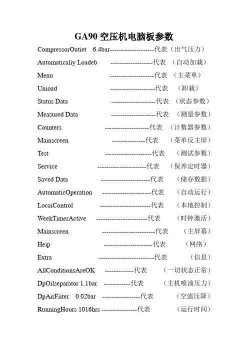
GA90空压机电脑板参数CompressorOutiet 6.4bar--------------------代表(出气压力)Automaticaliy Loadeb -------------------代表(自动加栽)Menu --------------------代表(主菜单)Unioad --------------------代表(卸栽)Status Data --------------------代表(状态参数)Measured Data --------------------代表(测量参数)Counters --------------------代表(计数器参数)Mainscreen ---------------代表(菜单反主屏)Test ---------------------代表(测试参数)Service ----------------------代表(保养定时器)Saved Data ----------------------代表(储存数据)AutomaticOperation ----------------------代表(自动运行)LocaiControl -----------------------代表(本地控制)WeekTimerActive -----------------------代表(时钟激活)Mainscreen ------------------------代表(主屏幕)Heip ----------------------代表(网络)Extra -------------------------代表(信息)AllConditionsAreOK -------------代表(一切状态正常)DpOilseparator 1.1bar ------------代表(主机喷油压力)DpAirFiiter 0.02bar -----------------代表(空滤压降)RunningHours 1016hrs ----------------代表(运行时间)LoadedHours 980hrs -------------代表(加栽时间)MotorStarts 945number ------代表(电机启动次数)DisplaiayTest --------------代表(不测试)SafetyValveTest -----------代表(安全测试)Menu ------------代表(安全阀)Parameters ------------代表(界限)Protections -----------代表(保护值)Service Plan --------代表(保养时间) Last Shutdown 1 -----------代表(上次故障停机) Loading Pressure ---------代表(加载压力) Unloading Pressure -------代表(卸载压力) Clock Function ------代表(时钟功能) Configuration --------------------代表(配置) Time ----------------------代表(时间) Date ----------------------------代表(日期) Date Domat DD/MMYY ---代表(日期格式) Elementoutlet-------------代表(头出口温度)Shutdwarnmax--------------代表(故障停机报警最大值) Servicerequire-------------代表(需要保养) Emergencystop-----------代表(紧急停机)Hightemperaturealarm -------代表(温度报警)LengGanmachinedewpoinetemptrature代表(干机露点温度)Oilgasseparatordifferenialpressure----代表(油气分离器压差)Fanoverload ----------------------------代表(风机过载)Hoseoverload ----------------------------代表(主机过载)Remotelyseule -------------------------代表(远程启动)Pressuresensorfauit-----------------------代表(压力传感器故障)The eemperaeuresensor------------------代表(温度传器故障)。
- 1、下载文档前请自行甄别文档内容的完整性,平台不提供额外的编辑、内容补充、找答案等附加服务。
- 2、"仅部分预览"的文档,不可在线预览部分如存在完整性等问题,可反馈申请退款(可完整预览的文档不适用该条件!)。
- 3、如文档侵犯您的权益,请联系客服反馈,我们会尽快为您处理(人工客服工作时间:9:00-18:30)。
.
精选范本
油过滤器压差 Dp Oil Filter
油分离器压差 Dp Oil Separator 主机喷油压力 Oil Injection Element 油压 Oil Pressure
空气过滤器压差 Dp Air Filter 主机1出口 Element 1 Outlet 压缩机出口 Compressor Outlet 紧急停机 Emergency Stop
远程起动/停机 Remote Start/Stop 远程加载/卸载 Remote Load/Unload 电机过载 Overload Motor
风扇电机过载 Overload Fanmotor
电机/风扇电机过载 Overload Motor/Fanmotor 起动器反馈触点 Starter Feedback Contact
压力带1开 / 压力带2关 PB1 open / PB2 closed 主机1电机过载 Overload Motor Element 1 远程加载/卸载2 Remote Load/Unload 2 电机正在运行 Motor Running 电机正在起动 Motor Starting 卸载/加载 Unloaded / Loaded 加载延时 Load Delay 报警 Warning 保养 Service 停机 Shutdown
远程启动 Remote Start 远程停止 Remote Stop 本地启动 Local Start 油过滤器 Oil Filter 油分离器 Oil Separator 空气过滤器 Air Filter 运行时间 Running Hours 加载时间 Loaded Hours 电机起动次数 Motor Starts
控制器运行时间 Module Hours 累计流量 Accumulated Volume 加载继电器 Load Relay 冷却介质 Cooling Medium 压缩机出口 Compressor Outlet 压缩机停 Compressor Off 电机已停止 Motor Stopped
自动卸载 Automatically Unloaded 自动加载 Automatically Loaded 手动卸载 Manually Unloaded 程序停机 Programmed Stop 起动过程 Startup Process 主页 Home page
停止 Stopped 卸载 Unloaded
运行/加载 Running/Loaded 维护状态 Service State 警告状态 Warning State 关机状态 Shutdown State
维护前警告 Pre-service Warning 维护警告 Service Warning 警告前 Pre-warning 警告 Warning
启动失败 Start Failure 关机 Shutdown 一切正常 No Problem 出口压力 Outlet Pressure 运行时间 Running Hours 密码 Password
压缩机控制模式 C.C.M. 时钟功能 Clock Function
本地通讯暂停 Communication Time-out 保护 Protection 维护保养 Service 起动失败 Start Failures 输入 Inputs
计划 Plan mm mm inch inch 预保养 Pre-Service 预报警 Pre-Warning 传感器故障 Sensor Error
压力单位 Pressure Unit bar bar psi psi MPa MPa kg/cm² kg/cm² 压缩机电机 Compressor Motor 风扇电机 Fan Motor 目录 List 取消 Cancel 程序 Program 限值 Limits
主显示屏 Mainscreen 菜单 Menu
显示更多 Show More 卸载 Unload 加载 Load 选择 Select
返回 Return 重置 Reset 修改 Modify 后退 Back 可以 OK 不可以 NOT OK 压缩机 Compressor 多机控制器 MCC
. 配置Configure
激活Activated
执行Execute
起动Start 本地Local
精选范本。