【US20200098440A1】ONETIMEPROGRAMMABLE(OTP)IMPLEMENT
prometheus 业务指标 time注解

prometheus 业务指标 time注解
“Prometheus 业务指标 time注解”这句话的意思是,在Prometheus监控系统中,对业务指标进行时间注解。
Prometheus是一个开源的监控系统,它主要用于收集和存储大量的时间序列数据。
时间注解是指将时间戳信息附加到业务指标上,以便记录业务指标在每个时间点的数值。
这种时间注解可以帮助Prometheus用户更好地理解和分析业务指标的趋势和变化。
Prometheus 业务指标 time注解主要包括以下方面:
1.时间戳注解:将每个数据点的时间戳信息记录下来,以便后续分析和追溯。
2.时间范围注解:将业务指标的时间范围进行标注,以便用户了解数据在特
定时间段内的变化情况。
3.时间序列注解:将业务指标的时间序列数据进行标注,以便用户了解数据
随时间变化的情况。
最后总结,Prometheus 业务指标 time注解是指将时间戳信息与业务指标相关联,以便更好地跟踪和分析业务性能数据。
这有助于Prometheus用户了解业务指标在特定时间点的状态和趋势,从而做出更明智的决策。
同时,时间注解还可以帮助用户更好地理解和分析业务指标的时间趋势和变化,提高监控系统的可用性和可维护性。
Unitronics UniStream HMI 面板安装指南说明书
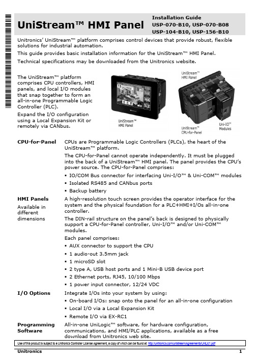
UniStream™ HMI Panel Installation GuideUSP-070-B10, USP-070-B08USP-104-B10, USP-156-B10 Unitronics’ UniStream™ platform comprises control devices that provide robust, flexible solutions for industrial automation.This guide provides basic installation information for the UniStream™ HMI Panel. Technical specifications may be downloaded from the Unitronics website.The UniStream™ platformcomprises CPU controllers, HMIpanels, and local I/O modulesthat snap together to form anall-in-one Programmable LogicController (PLC).Expand the I/O configurationusing a Local Expansion Kit orremotely via CANbus.CPU-for-Panel CPUs are Programmable Logic Controllers (PLCs), the heart of theUniStream™ platform.The CPU-for-Panel cannot operate independently. It must be pluggedinto the back of a UniStream™ HMI panel. The panel provides the CPU’spower source. The CPU-for-Panel comprises:▪IO/COM Bus connector for interfacing Uni-I/O™ & Uni-COM™ modules▪Isolated RS485 and CANbus ports▪Backup batteryHMI Panels Available indifferent dimensions A high-resolution touch screen provides the operator interface for the system and the physical foundation for a PLC+HMI+I/Os all-in-one controller.The DIN-rail structure on the panel’s back is designed to physically support a CPU-for-Panel controller, Uni-I/O™ and/or Uni-COM™modules.Each panel comprises:▪AUX connector to support the CPU▪1 audio-out 3.5mm jack▪1 microSD slot▪2 type A, USB host ports and 1 Mini-B USB device port▪2 Ethernet ports, RJ45, 10/100 Mbps▪1 power input connector, 12/24 VDCI/O Options Integrate I/Os into your system by using:▪On-board I/Os: snap onto the panel for an all-in-one configuration▪Local I/O via a Local Expansion Kit▪Remote I/O via EX-RC1Programming Software All-in-one UniLogic™ software, for hardware configuration, communications, and HMI/PLC applications, available as a freeHMI Panel Installation GuideBefore You BeginAlert Symbols and General RestrictionsWhen any of the following symbols appear, read the associated information carefully. Symbol Meaning DescriptionDanger The identified danger causes physical and property damage.Warning The identified danger could cause physical and property damage. Caution Caution Use caution.▪All examples and diagrams are intended to aid understanding, and do not guarantee operation. Unitronics accepts no responsibility for actual use of this product based on these examples.▪Please dispose of this product according to local and national standards and regulations. ▪This product should be installed only by qualified personnel.▪Failure to comply with appropriate safety guidelines can cause severe injury orproperty damage.▪Do not attempt to use this device with parameters that exceed permissible levels.▪Do not connect/disconnect the device when power is on.Environmental Considerations▪Ventilation: 10mm (0.4”) of space is required between the device top/bottom edges and the enclosure’s walls.▪Do not install in areas with: excessive or conductive dust, corrosive or flammablegas, moisture or rain, excessive heat, regular impact shocks or excessive vibration, in accordance with the standards and limitations given in the product’s technicalspecification sheet.▪Do not place in water or let water leak onto the unit.▪Do not allow debris to fall inside the unit during installation.▪Install at maximum distance from high-voltage cables and power equipment. Caution▪The UniStream™ HMI Panel is designed to comply with NEMA 4X, IP66 and IP65.Note however that the Audio Protection Seal must remain plugged in for NEMA4X and IP66, in which case the audio sound level from the internal speaker issignificantly reduced.UniStream™Kit Contents▪ 1 HMI Panel: 7”, 10.4” or 15.6”7” panel, includes 4 mounting brackets10.4” panel, includes 8 mountingbrackets and 2 panel supports15.6” panel, includes 10 mounting brackets and 2 panel supports▪ 1 panel mounting seal ▪ 1 programming cable ▪ 1 power terminal blockHMI Panel DiagramHMI Panel Front and Rear ViewCaution ▪ Keep the seal in place when the embedded speaker is not used. The seal mustHMI Panel Installation GuideInstallation Space ConsiderationsAllocate space for:▪The HMI Panel including the CPU and any modules that will be installed on it ▪Opening the doors of the CPU and modulesFor exact dimensions, please refer to the Mechanical Dimensions shown below. HMI Panel Mechanical Dimensions7” PanelUniStream™10.4” Panel15.6” PanelHMI Panel Installation GuidePanel MountingN OTE▪Mounting panel thickness must be less or equal to 5mm (0.2”).▪Ensure that the space considerations are met.1. Prepare a panel cut-out according to the dimensions of your model, USP-070-B10,USP-104-B10, or USP-156-B10 as shown in the previous section.2. Slide the panel into the cut-out,ensuring that the Panel Mounting Seal isin place as shown on the right.3. Push the mounting brackets into theirslots on the sides of the panel as shownbelow.4. Tighten the bracket screws against thepanel. Hold the brackets securelyagainst the unit while tightening thescrews.When properly mounted, the panel issquarely situated in the panel cut-out asshown below.USP-070-B10: 4 mounting brackets USP-104-B10: 8 mounting bracketsUSP-156-B10: 10 mounting bracketsUniStream™Wiring▪This equipment is designed to operate only at SELV/PELV/Class 2/Limited Powerenvironments.▪All power supplies in the system must include double insulation. Power supplyoutputs must be rated as SELV/PELV/Class 2/Limited Power.▪Do not connect either the ‘Neutral’or ‘Line’ signal of the 110/220VAC to device’s 0V point.▪Do not touch live wires.▪All wiring activities should be performed while power is OFF.▪Use over-current protection, such as a fuse or circuit breaker, to avoid excessivecurrents into the HMI Panel supply port.▪Unused points should not be connected (unless otherwise specified). Ignoring thisdirective may damage the device.▪Double-check all wiring before turning on the power supply.Caution ▪To avoid damaging the wire, use a maximum torque of 0.5 N·m (5 kgf·cm).▪Do not use tin, solder, or any substance on stripped wire that might cause thewire strand to break.▪Install at maximum distance from high-voltage cables and power equipment.Wiring ProcedureUse crimp terminals for wiring; use 26-12 AWG wire (0.13 mm2–3.31 mm2).1. Strip the wire to a length of 7±0.5mm (0.250–0.300 inches).2. Unscrew the terminal to its widest position before inserting a wire.3. Insert the wire completely into the terminal to ensure a proper connection.4. Tighten enough to keep the wire from pulling free.Wiring GuidelinesIn order to ensure that the device will operate properly and to avoid electromagnetic interference:▪Use a metal cabinet. Make sure the cabinet and its doors are properly earthed.▪Use wires that are properly sized for the load.▪Individually connect each 0V point in the system to the power supply 0V terminal.▪Individually connect each functional ground point () to the earth of the system (preferably to the metal cabinet chassis).Use the shortest and thickest wires possible: less than 1m (3.3’) in length, minimum thickness 14 AWG (2 mm2).▪Connect the power supply 0V to the earth of the system.N OTE For detailed information, refer to the document System Wiring Guidelines, located in the Technical Library in the Unitronics’ website.HMI Panel Installation GuideWiring the Power SupplyThe UniStream™ HMI Panel device requires an external 12/24VDC power supply.▪In the event of voltage fluctuations or non-conformity to voltage power supplyspecifications, connect the device to a regulated power supply.Connect the +V and 0V terminals as shownin the accompanying figure.HMI Panel Interface ConnectionsUse the following:Ethernet CAT-5e shielded cable with RJ45 connectorUSB Device Use the proprietary programming cable supplied with the deviceUSB Host Standard USB cable with Type-A plugmicroSD Standard microSDAudio Out 3.5mm stereo audio plug with shielded audio cableInstalling CPU-for-Panel, Uni-I/O™ & Uni-COM™ ModulesRefer to the Installation Guides provided with these modules.▪Turn off system power before connecting or disconnecting any modules or devices.▪Use proper precautions to prevent Electro-Static Discharge (ESD).Removing the Panel1. Disconnect the power supply.2. Remove all wiring and disconnect any installed devices according to the device’sinstallation guide.3. Unscrew and remove the mounting brackets, taking care to support the panel toprevent it from falling during this procedure.。
芯表 i-Series 自动化工作站说明书

DESIGNED FOR YOUREVOLVING WORKFLOW PRIORITIESBiomek i-Series Automated WorkstationsProvided by: (800)404-ATECAdvanced Test Equipment Rentals®i -Series 2 |ACCELERATED WORKFLOWS . Faster Discovery.YOU TALKED. WE LISTENED .Your priorities continue to evolve; ours never change.Because our priority is you.Your input and our experience led to the engineering of a liquid handling platform that enables you to get the trusted, reliable results you need from your application workflows.From your input, some recurring themes appeared. And from those themes emerged a common foundation—for hardware, software, accessories, consumables and support—that’s built-on:• Simplification, so you can focus more on science and less on managing your tools• Efficiency, to help you optimize productivity, increase walk-away time and learn more—faster • Adaptability, so the technology you invest in can grow with you, not grow obsolete • Reliability and support, to help maximize instrument uptime so your research is always moving forwardOn that customer-driven foundation, we’re building the future of laboratory automation.The benefits of an automated workstation from Beckman Coulter Life Sciences come from more than just an instrument. They’re realized thanks to synergy between:• Hardware • Software • Accessories • Consumables • Service and support| 3ADVANCING SCIENCE BY ACCELERATING AWIDE RANGE OF APPLICATIONS• Cell-based assays • High-throughput screening• High-content screening • Cell line development • Cell culture • Transfection• Continuous cell culture • Biologic bioanalysis • Proteomics, lipidomics, metabolomics • Synthetic biology • 3D cell models • Compound handling• Next-generationsequencing sample prep °Whole genome sequencing °Transcriptome sequencing°Target/exome capture °Amplicon sequencing °Cancer panels °HLA typing• Microarray sample prep °Genotyping °Gene expression• Nucleic acid sample prep °DNA/RNA isolation °DNA/RNA clean-up °DNA size selection °Plasmid prep • Sanger sequencing °Big dye clean-up • qPCR/PCR setupAutomation drives acceleration.This is true for pharma, biotech, academia and government-sponsored research—virtually any lab focused on genomics, cell biology, proteomics, drug discovery, forensics and related research areas.A sampling of drug discovery and basic research application areas that can benefit from Biomek automation:Many fields of research continue to accelerate at a rapid pace.Our commitment is to provide the innovative technology you need to maintain that pace—by simplifying your workflows, improving efficiency, increasing walk-away time and decreasing downtime.The most recent example of this commitment: Biomek i-Series Automated Workstations1.A sampling of genomics application areas that can benefit from Biomek automation:4 |EXPLORE THE BIOMEK i-SERIES AUTOMATEDRepresenting the best of what has made Biomek workstationsan industry leader—combined with enhancements suggestedby customers around the globe—Biomek i-Series AutomatedWorkstations have been designed to optimize dependabilityand walk-away time in mid- to high-throughput labs.Biomek i7 Automated Workstation Simplicity so you can focus moreon scienceBright, multiple color- and pattern-codedstatus light bar alerts you to the instrument’scurrent mode, even from across the room.Light Curtain provides key safety featureduring operation and method development.Internal LED light illuminates the instrumentdeck for easy access and monitoring of yourworkspace status.123Efficiency to help deliverhigher productivityRotating gripper with unique offset fingerdesign optimizes access to high-densitydecks, enabling more efficient workflows.Linear motion control increases positionalaccuracy for pipetting access tohigh-density labware.Large-volume, 1 mL multichannel pipettinghead expedites sample transfers andenables more efficient mixing steps.4561236948BIOMEK i-SERIES WORKSTATIONSENABLE “4D INTEGRATION”With access from 4 directions—right, left, back and below—i-Series workstations make it easy to integrate a growing menu of devices, components and accessories. Your Beckman Coulter team can help you withstandard integrations.WORKSTATIONSAdaptability to extend scale and reachGrid-based deck with simple accessoryinstallation enables quick workflow changes.Spacious, open-platform design enables access from all sides to enable integration of adjacent-to-deck and off-deckprocessing elements (e.g., analytical devices, external storage/incubation units, and labware feeders).78Trusted reliability and support to reduce downtimeSafeguard sample and reagent integrity from air particulates with enclosedversions of the Biomek i-Series Automated Workstations.910115127ACCESSORIES TO ENABLEAdditional components• Fly-by barcode reader forpositive sample ID, process and tracking of microplates • Labware feeders• Instrument carts (pictured) and tables• And a host of others depending on your specific needsDevice integrations and customization servicesTo further enhance the capabilities of your Biomek i-Series Automated Workstation, you can choose from a list of device integrations or ask for our customization services.Your support team will includeexperts who’ve integrated hundreds of third-party devices to meet a large variety of workflow needs.Biomek i5 Automated Workstation8 |INDUSTRY-LEADING BIOMEK SOFTWARE FOR i-SERIES THATStreamline workflows with SAMI EXAutomate full workflows with a process control supporting a wide variety of applications. Use the power of a planning scheduler and sample data drill-down to manage your assay.Simplify data management with DARTAutomation systems generate large quantities of data to manage. DART simplifies workflow data by transforming it into powerful information to inform your research decisions.Additional software solutions include:Biomek pipette tips from Beckman Coulter are certified to be:• RNase- and DNase-freeEnsures high-quality nucleic acid purification and reliable nucleic acid testing results.• DNA-free (human & mouse)/PCR inhibitionConfirms the absence of both human and mouse DNA contaminants that result in erroneous results and interfere with the PCR.• Endotoxin-freeAddresses endotoxin-sensitive applications, such as cell transformations and preparative protocols that use extracted biological material for in vivo experimentation.BIOMEK PIPETTE TIPS:THE MOST CRITICAL POINT OF CONTACTAll Biomek workstations are optimized to perform as complete systems. That’s why only Biomek pipette tips from Beckman Coulter Life Sciences are validated and approved for use with our workstations.Biomek pipette tips, racks and rack covers are molded from premium-grade, virgin polypropylene to provide chemical resistance during sample preparation, and to ensure the highest performance and quality control for your most exacting applications.T o make setup, method writing, and operation easy and efficient, Biomek software already includes point-and-click options for Biomek tip definitions, pipetting techniques and templates, and color-coded Biomek tip racks.Only Biomek pipette tips are validated and approved for use with Biomek workstations.WORLD-CLASS TRAINING, SERVICE AND SUPPORT ARE INSTRUMENTAL TO SUCCESSFrom online classes or instructor-led training, to on-siteapplication support – we’re committed to doing everythingpossible to ensure that you can operate your Biomekworkstation with confidence.In addition, when you choose a Biomek i-Series AutomatedWorkstation from Beckman Coulter Life Sciences, you canexpect support and maintenance from an organization that’srated higher for technical support than any major competitor.Further building on our commitment to world-class servi c e, thePROService Remote Monitoring System is now available tohelp maximize system uptime by shortening service calls andexpediting repair times.Instructor-led training or on-lineclasses help ensure that you canoperate your i-Series workstationwith confidence.Our customer support center directsa team of engineers with extensiveproduct knowledge who can trouble-shoot issues quickly and efficiently.T o help maximize instrument uptime, thePROService Remote Monitoring System can useITEMWITHOUT ENCLOSURE WITH ENCLOSU RE Dimensions for Biomek i5 Base Unit Width: 112 cm (44”)Depth: 81 cm (32”)Height: 104 cm (41”)Width: 112 cm (44”)Depth: 81 cm (32”)Height: 112 cm (44”)Dimensions for Biomek i7 Base Unit Width: 170 cm (67”)Depth: 81 cm (32”)Height: 104 cm (41”)Width: 170 cm (67”)Depth: 81 cm (32”)Height: 112 cm (44”)Maximum Height w/Door OpenN/A 147 cm (58”)Weight: Biomek i5 Base UnitMultichannel155 kg (341 lbs)181 kg (399 lbs)Span-8146 kg (322 lbs)172 kg (379 lbs)Weight: Biomek i7 Base UnitMultichannel199 kg (439 lbs)234 kg (516 lbs)Dual Multichannel234 kg (516 lbs)269 kg (593 lbs)Span-8190 kg (419 lbs)225 kg (496 lbs)Hybrid (Multichannel + Span-8)225 kg (496 lbs)260 kg (573 lbs)Introducing the i-Series to our family of Biomek Automated Workstations is just the beginning of our journey together. Biomek hardware, software and our growing applications portfolio will continue to evolve with your priorities in mind.Visit or speak with your Beckman Coulter representative to learn more.1 Currently in development© 2017 Beckman Coulter, Inc. All rights reserved. Beckman Coulter, the stylized logo, and the Beckman Coulter product and service marks mentioned herein are trademarks or registered trademarks of Beckman Coulter, Inc. in the United States and other countries.For Beckman Coulter’s worldwide office locations and phone numbers, please visit “Contact Us” at AAG-2215SB01.17 SYSTEM SPECIFICATIONS FOR BIOMEK i-SERIES AUTOMATED WORKSTATIONS。
英语翻译-可编程逻辑控制器

Programmable Logic Controllers1 Simple introductionA programmable logic controller (PLC) is a solid-state device used to control machine motion or process operation by means of a stored program. The PLC sends output control signals and receives input signals through input/output (I/O) devices.A PLC controls outputs in response to stimuli at the inputs according to the logic prescribed by the stored program. The inputs are made up of limit switches, pushbuttons, thumbwheels, switches, pulses, analog signals, ASCII serial data, and binary or BCD data from absolute position encoders. The outputs are voltage or current levels to drive end devices such as solenoids, motor starters, relays, lights and so on. Other output devices include analog devices, digital BCD displays, ASCII compatible devices, servo variable-speed drives, and even computers. Programmable controllers were developed (circa in 1986) when General Motors Corp, and other automobile manufacturers were experimenting to see if there might be an alternative to scrapping all their hardwired control panels of machine tools and other production equipment during a model changeover. This annual tradition was necessary because rewiring of the panels was more expensive than buying new ones.The automotive companies approached a number of control equipment manufacturers and asked them to develop a control system that would have a longer productive life without major rewiring, but would still be understandable to and repairable by plant personnel. The new product was named a “programmable controller”.The processor new part of the PLC contains a central processing until and memory. The central processing until (CPU) is the “traffic director” of the processor, the memory stores information. Coming into the processor are the electrical signals from the input devices, as conditioned by the input module to voltage levels acceptable to processor logic. The processor scans the state of I/O and updates outputs based on instruction stored in the memory of the PLC. For example, the processor may be programmed so that if an input connected to a limit switch is true (limit switch closed), then a corresponding output wired to an output module is to be energized. This output might be a solenoid, for example. The processor remembers this command through its memory and compares on each scan to see if that limitswitch is, in fact, closed. if it is closed, the processor energizes the solenoid by turning on the output module.The output device, such as a solenoid or motor starter, is wired to an output module’s terminal, and it receives its shift signal from the processor, in effect, the processor is performing a long and complicated series of logic decisions. The PLC performs such decisions sequentially and in accordance with the stored program. Similarly, analog I/O allows the processor to make decisions based on the magnitude of a signal, rather than just if it is on or off. For example, the processor may be programmed to increase or decrease the steam flow to a boiler (analog output) based on a comparison of the actual temperature in the boiler (analog input) to the desired temperature. This is often performed by utilizing the built-in PID (proportional, integral, derivative) capabilities of the processor.Because a PLC is “software based”, its control logic functions can be changed by reprogramming its memory. Keyboard programming devices facilitate entry of the revised program, which can be designed to cause an existing machine or process to operate in a different sequence or to respond to different levels of, or combinations of stimuli. Hard-ware modifications are needed only if additional, changed, or relocated input/output devices are involved.2 General Application Areas1.Sequence ControlThis is the largest and most common application of programmable controllers today, and is the closest to traditional relay control in its’ sequential’ nature. Because of the very general nature of this category, it is sometimes difficult to understand the breadth of power that it brings to so found on individual machines or machine lines, on conveyor and packaging machinery, and even on modern elevator control systems.2.Motion ControlThis is the integration of linear or rotary motion control in the programmable controller. This could be a single or multiple axis drive system control, and can be used with servo, stepper, or multiple axis drive system control, and can be used with servo, stepper, or hydraulic drives. In early systems, a stand-alone servo drive would be connected to the programmable controller with a series of individual conductors to discrete inputs and outputs. Newer systems integrate this functionality directlyinto the I/O racks through the use of special I/O boards dedicated to motion control. This eliminates the need to interface the two devices together with discrete I/O. Programmable controller motion control applications include an unending variety of machinery; metal cutting (grinders), metal forming (press brake), assembly machines, and multiple axes of motion can be coordinated for both discrete part and process industry applications. Examples of these would include Cartesian robots, and many web related processes that is film, rubber, and non-weave textile systems.3.Process ControlThis is the ability of the programmable controller to control a number of physical parameters such as temperature, pressure, velocity, and flow. This involves the use of analog (continuously variable) I/O to achieve a close-loop control system. The use of Proportion-Integral-Derivative (PID) , software always allow the programmable controller to replace the function of stand-alone loop controllers. Another alternative is to integrate the loop controllers with the programmable controller, retaining the best features of each. Typical examples of applications include plastic injection molding machines, extrusion process machines, heat treat furnaces, and many other batch-type control applications.4.Data ManagementThe ability to collect, analyze, and manipulate data has only become possible with programmable controllers in the last few years. With the advanced instruction sets and expanded variable memory capacities of the newer programmable controllers, it is now possible for the system to act as a data concentrator, collecting data about the machine or process it is controlling. This data can then be sent via a communication function to another intelligent device for analysis or report generation. Any comments that are made about the importance and growing use of data management are probably understatements considering the leap-frog technical solution capabilities it brings to a wide range of applications. Data management is frequently found on large materials handling systems, in unmanned flexible manufacturing cells, and in many process industry applications, that is, paper, primary metals, and food processing.3 programmable automationFor programmable automation, the equipment is designed in such a way that the sequence of production operations is controlled by a program, i.e., a set of codedinstructions that can be read and interpreted by the system. Thus the operation sequence can be readily changed to permit different product configurations to be produced on the same equipment. Some of the features that characterize programmable automation include 1. high investment in general-purpose programmable equipment, 2. lower production rates than fixed automation, 3. flexibility to deal with changes in product configuration, and 4. suited to low and/or medium production of similar products or parts (e. g. part families). Examples robots, and programmable logic controllers.Programmable production systems are often used to produce parts or products in batches. They are especially appropriate when repeat orders for batches of the same programmed with the set of machine instructions that correspond to that product. The physical setup of the equipment must be loaded. This changeover procedure can be time-consuming. As a result, the usual production cycle for a given batch includes 1. a period during which the setup and reprogramming is accomplished and 2. a period in which the batch is processed. The setup –reprogramming period constitutes nonproductive time of the automated system.The economics of programmable automation require that as the setup-reprogramming time increases, the production batch size must be made larger so as to spread the cost of lost production time over a larger number of units. Conversely, if setup and reprogramming time can be reduced to zero, the batch size can be reduced to one. This is the theoretical basis for flexible automation, an extension of programmable automation. A flexible automated system is one that is capable of producing a variety of products (or parts) with minimal lost time for changeovers from one product to the next. The time to reprogram the system and alter the physical setup is minimal and results in virtually no lost production time. Consequently, the system is capable of producing various combinations and schedules of products in a continuous flow. Rather than batch production with interruptions between batches. The features of flexible automation are:1.high investment for a custom-engineered system.2.continuous production of mixtures of products.3.ability to change product mix to accommodate changes in demand rates forthe different products made.4.medium production rates.5.flexibility to deal with product design variations.可编程逻辑控制器1 简单介绍可编程逻辑控制器(PLC)是一种固态电子装置,它利用已存入的程序来控制机器的运行或工艺的工序。
一文 precision time protocol -回复

一文precision time protocol -回复什么是精确时间协议(PTP)?精确时间协议(PTP),又称为IEEE 1588协议,是一种网络协议,旨在提供高精度的时间同步。
它能够通过网络将时间信息传播到网络中的各个节点,使得节点间能够保持高度一致的时间。
这使得PTP在各种应用场景中得到广泛应用,尤其是需要高精度时间同步的领域,如金融交易、工业控制和通信系统。
PTP通过利用网络中的主从结构来实现时间同步。
网络中的一个节点被指定为主时钟(Master Clock),负责产生精确的时间信号。
其他节点则被指定为从时钟(Slave Clock),通过与主时钟进行通信来同步时间。
当从时钟接收到主时钟的时间信号时,它会与自己内部的本地时钟进行比对,并对本地时钟进行调整,从而保持与主时钟的高度一致。
PTP的工作原理可以简单概括为以下几个步骤:1. 主时钟配置:首先,需要将一个节点设置为主时钟,并进行其它一些必要的配置。
主时钟需要有稳定的时钟源,可以是原子钟或GPS接收器等精确的时间源。
2. 从时钟加入:接下来,其他节点需要与主时钟进行通信来加入网络。
从时钟会向主时钟发送加入请求,主时钟会为其分配一个时钟标识符,并指定主从时钟的相关参数。
3. 时间同步:一旦从时钟成功加入网络,主时钟会周期性地向从时钟发送时间戳消息。
时间戳消息包含主时钟的当前时间信息。
从时钟接收到时间戳消息后,会与其本地时钟进行比较,并计算出主从时钟之间的时间差。
从时钟根据时间差来对本地时钟进行微小调整,以与主时钟保持同步。
4. 时钟调整:由于网络延迟等因素的存在,从时钟与主时钟之间可能会存在微小的时间差。
为了确保整个网络中的时钟能够保持一致,PTP使用了时钟调整机制。
该机制利用反馈控制算法来逐渐调整从时钟的频率和相位,从而使其尽可能地接近主时钟。
从这些步骤中可以看出,PTP是一种分布式的时间同步机制。
通过网络中的主从结构、时间戳消息的交换和时钟调整,PTP实现了高精度的时间同步。
MEMORY存储芯片MT29F16G08DAAWP中文规格书

One-Time Programmable (OTP) OperationsThis Micron NAND Flash device offers a protected, one-time programmable NAND Flash memory area. Each target has a an OTP area with a range of OTP pages (see Ta-ble 15 (page 102)); the entire range is guaranteed to be good. Customers can use the OTP area in any way they desire; typical uses include programming serial numbers or other data for permanent storage.The OTP area leaves the factory in an erased state (all bits are 1). Programming an OTP page changes bits that are 1 to 0, but cannot change bits that are 0 to 1. The OTP area cannot be erased, even if it is not protected. Protecting the OTP area prevents further programming of the pages in the OTP area.Enabling the OTP Operation ModeThe OTP area is accessible while the OTP operation mode is enabled. To enable OTP operation mode, issue the SET FEATURES (EFh) command to feature address 90h and write 01h to P1, followed by three cycles of 00h to P2 through P4.When the target is in OTP operation mode, all subsequent PAGE READ (00h-30h) and PROGRAM PAGE (80h-10h) commands are applied to the OTP area.ERASE commands are not valid while the target is in OTP operation mode.Programming OTP PagesEach page in the OTP area is programming using tthe PROGRAM OTP PAGE (80h-10h)command. Each page can be programmed more than once, in sections, up to the maxi-mum number allowed (see NOP in Table 15 (page 102)). The pages in the OTP area must be programmed in ascending order.If the host issues a PAGE PROGRAM (80h-10h) command to an address beyond the max-imum page-address range, the target will be busy for t OBSY and the WP# status register bit will be 0, meaning that the page is write-protected.Protecting the OTP AreaTo protect the OTP area, issue the OTP PROTECT (80h-10h) command to the OTP Pro-tect Page. When the OTP area is protected it cannot be programmed further. It is not possible to unprotect the OTP area after it has been protected.Reading OTP PagesTo read pages in the OTP area, whether the OTP area is protected or not, issue the PAGE READ (00h-30h) command.If the host issues the PAGE READ (00h-30h) command to an address beyond the maxi-mum page-address range, the data output will not be valid. To determine whether the target is busy during an OTP operation, either monitor R/B# or use the READ STATUS (70h) command. Use of the READ STATUS ENHANCED (78h) command is prohibited while the OTP operation is in progress.Returning to Normal Array Operation ModeTo exit OTP operation mode and return to normal array operation mode, issue the SET FEATURES (EFh) command to feature address 90h and write 00h to P1 through P4.If the RESET (FFh) command is issued while in OTP operation mode, the target will exit OTP operation mode and enter normal operating mode. If the synchronous interface is active, the target will exit OTP operation and enable the asynchronous interface.16Gb, 32Gb, 64Gb, 128Gb Asynchronous/Synchronous NAND One-Time Programmable (OTP) OperationsInterleaved Die (Multi-LUN) OperationsIn devices that have more than one die (LUN) per target, it is possible to improve per-formance by interleaving operations between the die (LUNs). An interleaved die (multi-LUN) operation is one that is issued to an idle die (LUN) (RDY = 1) while another die (LUN) is busy (RDY = 0).Interleaved die (multi-LUN) operations are prohibited following RESET (FFh, FCh), iden-tification (90h, ECh, EDh), and configuration (EEh, EFh) operations until ARDY =1 for all of the die (LUNs) on the target.During an interleaved die (multi-LUN) operation, there are two methods to determine operation completion. The R/B# signal indicates when all of the die (LUNs) have finish-ed their operations. R/B# remains LOW while any die (LUN) is busy. When R/B# goes HIGH, all of the die (LUNs) are idle and the operations are complete. Alternatively, the READ STATUS ENHANCED (78h) command can report the status of each die (LUN) in-dividually.If a die (LUN) is performing a cache operation, like PROGRAM PAGE CACHE (80h-15h),then the die (LUN) is able to accept the data for another cache operation when status register bit 6 is 1. All operations, including cache operations, are complete on a die when status register bit 5 is 1.Use the READ STATUS ENHANCED (78h) command to monitor status for the ad-dressed die (LUN). When multi-plane commands are used with interleaved die (multi-LUN) operations, the multi-plane commands must also meet the requirements, see Multi-Plane Operations for details. After the READ STATUS ENHANCED (78h) command has been issued, the READ STATUS (70h) command may be issued for the previously ad-dressed die (LUN).See Command Definitions for the list of commands that can be issued while other die (LUNs) are busy.During an interleaved die (multi-LUN) operation that involves a PROGRAM-series(80h-10h, 80h-15h, 80h-11h) operation and a READ operation, the PROGRAM-series op-eration must be issued before the READ-series operation. The data from the READ-series operation must be output to the host before the next PROGRAM-series operation is issued. This is because the 80h command clears the cache register contents of all cache registers on all planes.16Gb, 32Gb, 64Gb, 128Gb Asynchronous/Synchronous NAND Interleaved Die (Multi-LUN) OperationsTable 13: Parameter Page Data Structure (Continued)16Gb, 32Gb, 64Gb, 128Gb Asynchronous/Synchronous NAND Parameter Page Data Structure Tables。
同步跨时钟域的约束处理

同步跨时钟域的约束处理同步跨时钟域的约束处理是数字设计中一个非常重要的问题,涉及到两个或多个时钟域之间的数据传输。
由于不同的时钟域有各自的时钟频率和相位,因此在从一个时钟域向另一个时钟域传输数据时,可能会出现数据丢失、数据冲突或者不确定状态等问题。
为了解决这些问题,需要进行同步处理。
以下是一些同步跨时钟域的约束处理方法:1. 建立时钟域之间的同步关系:在两个时钟域之间建立同步关系,使得它们之间的数据传输能够有序进行。
常用的同步方法有使用FIFO(先进先出)队列、使用双缓冲区、使用握手协议等。
2. 避免数据冲突:在跨时钟域的数据传输中,如果接收端无法及时接收数据,可能会导致数据冲突。
为了避免这种情况,可以采用以下方法:* 使用具有足够缓冲区的FIFO队列,以容纳接收端暂时无法处理的数据。
* 使用双缓冲区技术,将接收端的数据存储在两个缓冲区中,以避免在一个缓冲区中积累过多的数据。
* 在数据传输前进行握手协议,确保接收端准备好接收数据。
3. 消除不确定状态:在跨时钟域的数据传输中,由于时钟域之间的时钟频率和相位可能不同,可能会导致数据状态不确定。
为了消除这种不确定状态,可以采用以下方法:* 使用分频或倍频技术,使得发送端和接收端的时钟频率相同或相近。
* 使用同步器或去抖动器,将接收端的数据同步到发送端的时钟域中。
4. 考虑时序约束:在数字设计中,时序约束是非常重要的。
在进行跨时钟域的约束处理时,需要考虑时序约束,以确保数据传输的正确性。
例如,在建立FIFO队列时,需要考虑读写时序的约束;在使用同步器或去抖动器时,需要考虑信号传输的时序约束等。
综上所述,同步跨时钟域的约束处理是数字设计中一个非常重要的问题,需要进行综合考虑和处理。
sametime协议

sametime协议1.引言S a me ti me协议是一种用于实时通信的协议,旨在提供高效、安全和可靠的即时通讯服务。
本文将介绍Sa me ti m e协议的定义、功能、使用场景以及一些重要的技术细节。
2. Sa metime协议的定义S a me ti me协议是一种由IB M开发的实时通信协议,用于在企业内部或网络中进行即时消息传递、语音通话和视频会议。
它基于标准的互联网协议,如TC P/IP和H T TP,并使用XM L格式进行数据交换。
3. Sa metime协议的功能3.1即时消息传递S a me ti me协议提供了即时消息传递的功能,用户可以通过Sa m et im e 客户端发送和接收文字消息。
这种消息传递方式快速且实时,使得交流变得更加高效和便捷。
3.2语音通话S a me ti me协议支持实时语音通话功能,用户可以通过Sa me ti m e客户端进行语音通话。
这种功能非常适用于远程办公、团队协作以及业务沟通等场景。
3.3视频会议S a me ti me协议还支持视频会议功能,用户可以通过S am et im e客户端进行多方视频通话和会议。
这种功能非常有助于远程团队协作、在线培训和远程面试等场景。
4. Sa m e t i m e协议的使用场景4.1企业内部通信在企业内部,员工可以使用S am et im e协议进行即时消息传递、语音通话和视频会议,实现团队内部的高效沟通和协作。
4.2远程办公对于远程办公的团队而言,S am et im e协议提供了即时通讯和远程协作的功能,使得远程工作变得更加便捷和高效。
4.3客户服务使用Sa me ti me协议,客服人员可以与客户进行实时的文字聊天,提供解决方案和快速的技术支持,提高客户满意度。
5. Sa metime协议的重要技术细节5.1安全性S a me ti me协议提供了多种安全机制,包括加密通信和身份验证,以确保通信的安全性和保密性。