阿拉丁-广州镇流器终稿V1.0
EN 15085-2-2007 英文版 Railway applications- Welding of railway vehicles and components- Part 2 Qual
ICS 25.160.10; 45.060.01
EN 15085-2
October 2007
English Version
Applications ferroviaires - Soudage des véhicules et des composants ferroviaires - Partie 2: Exigences de qualité et certification du constructeur
ZZ
Z
EUROPEAN COMMITTEE FOR STANDARDIZATION COMITÉ EUROPÉEN DE NORMALISATION EUROPÄISCHES KOMITEE FÜR NORMUNG
E] I
Management Centre: rue de Stassart, 36
© 2007 CEN
All rights of exploitation in any form and by any means reserved worldwide for CEN national Members.
[Z F R
B-1050 Brussels
Railway applications - Welding of railway vehicles and components - Part 2: Quality requirements and certification of welding manufacturer
This European Standard was approved by CEN on 18 August 2007.
DU8634Z
DS _DU8634Z_CN_V1.1
极限参数(1)(2)
DU8634Z
高压高精度 LED 恒流驱动器
符号
脚位
描述
范围
单位
---
3,8 模拟输入/输出引脚
-0.3~6
V
Ivcc
3 VCC 最大钳位电流
10
mA
θJA
--- 热阻(结温-环境)
Tj
--- 最大工作结温
150 -40~150
℃/W ℃
Tstg
概述
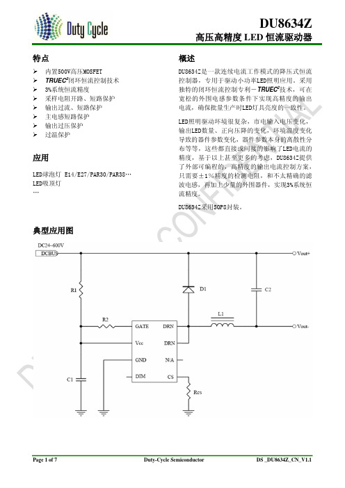
DU8634Z是一款连续电流工作模式的降压式恒流 控制器,专用于驱动小功率LED照明应用。采用 独特的闭环恒流控制专利-TRUEC2技术,可在 宽松的外围电感参数条件下实现高精度的输出 电流,确保批量生产时LED灯具亮度的一致性。
LED照明驱动环境很复杂,市电输入电压变化, 输出LED数量、正向压降的变化,环境温度变化 导致的器件参数变化,器件参数本身的离散性分 布等等,这些都直接或间接的影响了LED电流的 精度,基于以上甚至更多的考虑,DU8634Z提供 了外部可编程的,高精度的输出电流控制方案, 只需要±1%精度的检测电阻,和不太精确的滤 波电感,再加上少量的外围器件,实现3%系统恒 流精度。
--- 存储温度范围
-65~150
℃
---
4 GATE 脚最大电压范围
-0.3~25
V
说明: (1) 最大极限值是指超出该工作范围,芯片可能损坏。电气参数定义了器件在工作范围内并且在保证特定性能指标的测试
条件下的直流和交流电参数规范。对于未给定上下限值的参数,该规范不予保证其精度,但其典型值反映了器件性能。 (2) 无特别说明,所有的电压以GND作为参考。 (3) 芯片内部高压MOSFET的连续导通电流是基于芯片温升小于40℃所得,如果温升高于40℃将会触发OTP保护。应用中建
广州数控设备 GSK 980MDa 说明书

前 言在本使用手册中,我们将尽力叙述各种与该系统操作相关的事项。
限于篇幅限制及产品具体使用等原因,不可能对系统中所有不必做和/或不能做的操作进行详细的叙述。
因此,本使用手册中没有特别指明的事项均视为“不可能”或“不允许”进行的操作。
本使用手册的版权,归广州数控设备有限公司所有,任何单位与个人进行出版或复印均属于非法行为,广州数控设备有限公司将保留追究其法律责任的权利。
IGSK980MDa钻铣床CNCII前 言尊敬的客户:对您选用广州数控设备有限公司的产品,本公司深感荣幸与感谢!本使用手册详细介绍了GSK980MDa 、GSK980MDa1、GSK980MDa-V 钻铣床CNC 的编程、操作及安装连接事项。
为了保证产品安全、正常与有效地运行工作,请您务必在安装、使用产品前仔细阅读本使用手册。
安 全 警 告操作不当将引起意外事故,必须要具有相应资格的人员才能操作本系统。
特别提示: 安装在机箱上(内)的系统电源,是仅为本公司制造的数控系统提供的专用电源。
禁止用户将这个电源作其他用途使用。
否则,将产生极大的危险!安 全 注 意 事 项安 全 注 意 事 项■运输与储存z产品包装箱堆叠不可超过六层z不可在产品包装箱上攀爬、站立或放置重物z不可使用与产品相连的电缆拖动或搬运产品z严禁碰撞、划伤面板和显示屏z产品包装箱应避免潮湿、暴晒以及雨淋■开箱检查z打开包装后请确认是否是您所购买的产品z检查产品在运输途中是否有损坏z对照清单确认各部件是否齐全,有无损伤z如存在产品型号不符、缺少附件或运输损坏等情况,请及时与本公司联系■接线z参加接线与检查的人员必须是具有相应能力的专业人员z产品必须可靠接地,接地电阻应小于0.1Ω,不能使用中性线(零线)代替地线 z接线必须正确、牢固,以免导致产品故障或意想不到的后果z与产品连接的浪涌吸收二极管必须按规定方向连接,否则会损坏产品z插拔插头或打开产品机箱前,必须切断产品电源■检修z检修或更换元器件前必须切断电源z发生短路或过载时应检查故障,故障排除后方可重新启动z不可对产品频繁通断电,断电后若须重新通电,相隔时间至少1minIIIGSK980MDa钻铣床CNCIV本手册的内容如有变动,恕不另行通知。
上海市经济信息化委关于2012年第二季度软件企业认定和软件产品登记的函

上海市经济信息化委关于2012年第二季度软件企业认定和软件产品登记的函文章属性•【制定机关】上海市经济和信息化委员会•【公布日期】2012.07.25•【字号】沪经信软[2012]443号•【施行日期】2012.07.25•【效力等级】地方规范性文件•【时效性】现行有效•【主题分类】计算机软件著作权正文上海市经济信息化委关于2012年第二季度软件企业认定和软件产品登记的函(沪经信软【2012】443号)市财政局、市国税局、市地税局、上海海关:根据《软件企业认定标准及管理办法(试行)》(信部联产〔2000〕968号)和《软件产品管理办法》(工业和信息化部第9号令),2012年第二季度,经上海市软件企业认定联席会议办公室审核,上海嘉骏信息科技有限公司等137家企业符合软件企业认定标准,认定为软件企业;华鸢机电SYH604梳棉机控制软件V1.0等756个产品(其中进口软件产品6个)符合软件产品登记条件,进行软件产品登记;Daedalus项目管理协同平台软件V1.0 (延续)等94个产品符合软件产品延续登记条件,进行软件产品延续登记。
请帮助落实相关政策。
上海市经济和信息化委员会2012年7月25日附件12012年4月份上海市认定软件企业名单注:①序号中标记“*”的为重新认定的软件生产企业。
②序号中标记“#”的为符合《财政部国家税务总局关于进一步鼓励软件产业和集成电路产业发展企业所得税政策的通知》(财税〔2012〕27号)相关条件的软件企业。
附件2注:①序号中标记“*”的为重新认定的软件生产企业。
②序号中标记“#”的为符合《财政部国家税务总局关于进一步鼓励软件产业和集成电路产业发展企业所得税政策的通知》(财税〔2012〕27号)相关条件的软件企业。
附件3注:①序号中标记“*”的为重新认定的软件生产企业。
②序号中标记“#”的为符合《财政部国家税务总局关于进一步鼓励软件产业和集成电路产业发展企业所得税政策的通知》(财税〔2012〕27号)相关条件的软件企业。
DS-B10视频综合平台用户手册

序号
1 2
接口
LOAD +/ LOAD BAT +/ BAT -
功能
-48V 直流输出,为视频综 合平台主机箱供电。 外接蓄电池接口。
说明
关于视频综合平台标配电源适配器的风扇、网口等使用方法,详请参见电源适配器产品说明。
杭州海康威视数字技术股份有限司| 版权所有(C)
6
视频综合平台用户手册
杭州海康威视数字技术股份有限公司| 版权所有(C)
1
视频综合平台用户手册
目录
目 录 .................................................................................................................................... 1 1 产品概述 ......................................................................................................................... 1
杭州海康威视数字技术股份有限公司| 版权所有(C)
2
视频综合平台用户手册
网络功能
• 支持多个千兆网络接口,用于网络视频的实时预览、解码上墙及网络集中存储等; • 支持 TCP/IP 协议簇,支持 TCP、UDP、RTP、PPPoE、DHCP、DNS、DDNS、SADP 等协议; • 支持单播和组播; • 支持网络扩展信号量报警输入输出控制; • 支持远程控制模拟、数字视频的切换上墙; • 支持远程获取和配置参数,支持远程导出和导入参数; • 支持远程获取系统运行状态、系统日志; • 支持远程重启、恢复默认设置、升级等日常维护。
FCI-600恒流风扇终端单元说明书

F CI-6CON STA NTVOLUME The METALAIRE FCI series fan-powered terminal unit has been engineered to provide a balance between quiet operation, minimal footprint, and a broad flow range.The FCI is constructed from 20 gauge metal designed to mitigate vibration and increase rigidity. The unique 4-piece case allows for fewer seams to minimize leakage. Every FCI includes bottom motor/blower access panel: These simple-to-remove panels provide access to allow trouble-free maintenance of the fan motor and blower assembly. The control enclosure for the FCI allows critical component access. FCI units include 1" thick, matte-faced fiberglass insulation that complies with UL 181 horizontal burn test, NFPA 90A and UL 723/ASTM E 84 flame spread and smoke developed ratings of 25/50. Optional insulations include metal-foil-faced and fiber- and erosion-free ThermoPure (closed-cell foam), a polyolefin product with superior acoustical properties compared to solid metal duct liner.Optional electronically commutated motors (ECM) are available to minimize energy usage. Up to 75% energy savings is typical with the ECM option.STANDARD FEATURES■ Available in 6 casing sizes to handle 200–4400 CFM.■ 20 gauge galvanized steel casing.■ Low leakage construction.■ Low leakage inlet damper (< 1% at 3" static pressure).■ Optional factory calibrated controls per each job requirement.■ Metalaire inlet flow sensor provides +/- 5% accuracy even with 90 degree elbow at inlet. ■ Easy access, steel balancing taps.■ Energy efficient PSC motors with adjustable SCR solid state fan speed controller.■ External control cabinet with offset mounting plate.■ Single point electrical connections.■ Beaded primary inlet connection tube for added rigidity and secure flex duct connections.■ Round inlets available in sizes 6" through 16".■ 1" thick, dual density (1.5lb / ft 3 min.) fiberglass insulation with edges coated.■ Rectangular discharge with optional slip and drive cleat duct connection.■ Large removable bottom access panel provides access to fan motor / blower assembly.■ Independently tested and certified laboratory performance data.■ Full range of options and accessories available (heating coils, disconnects, attenuators, etc.).■ Full range of liners / insulation available.■ Auto and manual thermal resets on every electric heater.■ High efficiency six-pole, single speed permanent split capacitor (PSC) motors.■ Available fan motor voltages of 120, 277, and 208-240 (50 / 60 Hz).FCI-600 CONSTANT VOLUME FAN AIR TERMINAL UNITFCI-600CONSTANT VOLUME FAN FEATURES AND BENEFITS1 2 of casing.3 4 for added rigidity.5 6 7 8 9 10 thermoplastic bearing.View of FCI-600 with bottom access panels removed.F CI-6CON STA NTVOLUM E Top ViewInlet View Discharge ViewThe standard location for control enclosure is Left Hand on Model FCI.Looking in the direction of airflow, the control enclosure is on the left.Air Filter Sizes Are Equal To Induction Attenuator dimensions A & B Field Connected Induction Duct Dimensions Should Equal A - 2" & B - 2" with a 1" Flange Air Flow FCI-600 SERIES FAN POWERED AIR TERMINAL UNIT COOLING ONLY The standard location for control enclosure is Left Hand on Model FCI.Looking in the direction of airflow, the control enclosure is on the left.F CI-6CON STA NTVOLUM E FCI-600 SERIES FAN POWERED AIR TERMINAL UNIT WITH ELECTRIC HEAT Top ViewInlet View Discharge ViewThe standard location for control enclosure is Left Hand on Model FCI.Looking in the direction of airflow, the control enclosure is on the left.Air Filter Sizes Are Equal To Induction Attenuator dimensions A & B Field Connected Induction Duct Dimensions Should Equal A - 2" & B - 2" with a 1" Flange Air Flow The standard location for control enclosure is Left Hand on Model FCI.Looking in the direction of airflow, the control enclosure is on the left.The standard location for control enclosure is Left Hand on Model FCI.F CI-6CON STA NTVOLUM E FCI-600 ECM SERIES FAN POWERED AIR TERMINAL UNIT WITH HOT WATER COIL Top ViewInlet View Discharge ViewThe standard location for control enclosure is Left Hand on Model FCI.Looking in the direction of airflow, the control enclosure is on the left.Air Filter Sizes Are Equal To Induction Attenuator dimensions A & B Field Connected Induction Duct Dimensions Should Equal A - 2" & B - 2" with a 1" Flange Air Flow 3&4 Row The standard location for control enclosure is Left Hand on Model FCI.Looking in the direction of airflow, the control enclosure is on the left.The standard location for control enclosure is Left Hand on Model FCI.F C I -600 C O N S T A N T V O L U M E FCI-600 APPROXIMATE SHIPPING WEIGHTS FCI-600 FILTER SIZESPER CASE SIZEFilters are mounted on the fan induction and are available in 1" or 2" thickness.■ Units tested per ASHRAE Standard 130-2016.■ All model sizes certified in accordance with AHRI 880-2017 certification program.■ ETL listed to meet requirements of UL 1995 and CSA 236.■ Dual-density fiberglass insulation meets UL 181 and NFPA 90A/90B.■ Insulation meets ASHRAE 62.1 requirements for resistance to mold growth and erosion.■ Hot water coils are manufactured in accordance to AHRI Standard 410.CERTIFICATIONS AND STANDARDSF CI-6CON STA NTVOLUM E 1) AHRI certified data is highlighted while all other data are application ratings 2) Radiated sound is the noise transmitted through the unit casing 3) Sound power levels expressed in decibels, (dB) re 10-12 Watts 4) Min ΔPs is the minimum operating pressure requirement of the unit with the damper full open and is the static pressure drop from the unit inlet to the unit discharge 5) Performance data based on laboratory tests conducted in accordance with ASHRAE 130-2016 and AHRI 880-20176)NC values are calculated using attenuation credits outlined in AHRI 885-2008Appendix E 7) Blank spaces indicate Minimum Ps if unit exceeds the ΔPs across the unit8)Sound performance based on units lined with standard dual density fiberglass insulation9)Discharge (external) static pressure is 0.25” w.g. for all casesRADIATED SOUND MODEL FCI - PSC MOTORF CI-6CON STA NTVOLUM E FCI-600 PSC FAN MOTOR AMPERAGE RATINGSFCI-600 DAMPER LEAKAGE FCI-600 ECM FAN MOTOR AMPERAGE RATINGSPERFORMANCE NOTESF CI-6CON STA NTVOLUM E FCI-600 HOT WATER COILS When ordered with the air terminal, the hot water coil is shipped attached to the discharge of the terminal casing. The discharge end of the casing has slip and drive connections for easy connection to downstream ductwork. The hot water coil is constructed of aluminum fin and copper serpentine-type tubes with male sweat connections tested at 300 psig.Coil selection can be made using METALAIRE’s Air Terminal Unit Selection Software. Contact your representative for a copy. In the interest of energy conservation and due to the possibility of condensation, all hot water coils are marked “Coil must be externally insulated after installation in the field.” Hot water coils are tested in accordance with AHRI Standards 410. Hot water coils may be ordered with optional access doors for inspection and cleaning to meet requirements of ASHRAE Standard 62.1.HOT WATER COIL CONSTRUCTION DETAILS ■ Hot Water Coils are factory mounted to the discharge of the terminal and are available with an optional factory mounted discharge plenum section with access door. ■ Hot water coils are enclosed in a 20 gauge coated steel casing allowing for attachment to metal ductwork with a slip and drive connection.■ Fins are rippled and sine wave type constructed from heavy gauge aluminum and are mechanically bonded to the tubes.■ Tubes are copper with a minimum wall thickness of 0.016" with male sweat header connections.■ Coils are leak tested to 300 psi with minimum burst of 2000 psi at ambient temperature. Coil performance data is based on tests run in accordance withAHRI standard 410. Coils are AHRI certified and include an AHRI label.All accessories that can be attached to the Series Fan Boxes are not a part of the AHRI certification program but ratings can be affected by their use.FCI-600 COIL CONNECTION SIZEF CI-6CON STA NTVOLUM E1) All coil performance in accordance with AHRI Standard 410-20012) Heating capacities are in MBH 3) Performance data based on a temperature differential of 115°F (180°F entering water temperature and 65°F entering air temperature)4) For temperature differentials other than 115°F , multiply the MBH by the correction factors below 5) Head Loss is in feet of water6) Airside ΔPs is the air pressure drop of the hot water coil7) Aire temperature rise =927 x MBH/CFM8) Water temperature drop = 2.04 x MBH/GPM9) Values in tables are listed for 0 ft. of altitude and no glycol in the system MBH CORRECTION FACTORSELECTRIC HEATER ASSEMBLY CONSTRUCTION DETAILSElectric Reheat Coils are factory mounted on the discharge of the Air Terminal. The heaters are ETL® listed for zero clearance, are tested in accordance Standard 1995, CSA-C22.2 No. 236 and the National Electric Code (NEC). Heater casings are constructed of galvanized steel. Element wire is high grade nichrome alloy derated to 45 watts per square inch density. Element wire is supported by moisture-resistant steatite ceramics.F CI-6CON STA NTVOLUM E FCI-600 ELECTRIC HEATER CAPACITIES NOTES:1. Heaters less than 10 kW are specifiable to nearest 0.5 kW. Heaters greater than 10.0 kW are specifiable to nearest 1.0 kW.2. Minimum flow rate for electric heat is 70 CFM / kW. Lower CFM’s can cause nuisance tripping, excessive discharge temperatures, rapid cycling, and rapid element failure. Electric Heat units running below 70 CFM / kW will void all warranties.3. For optimum thermal comfort, the suggested discharge temperature should not exceed 20°F above room set point.4. We do not recommend discharge temperatures in excess of 115°F to protect heater coils.5. Maximum number of steps at “Min kW per Step” is one step.6. If more than 1 heater is wired into a building’s circuit breaker (multi-outlet branch circuit), each heater will require the additionof power side fusing.ELECTRIC HEAT SELECTION:A. Specify electric duct heaters using voltage, phase, kW, and number of steps.B. Use above chart to select voltage. Calculate required kW using following equations: kW = BTU / HR kW = CFM X Δ X 1.085 Δ = kW X 3413 3413 3413 CFM X 1.085 CFM = kW X 3413 CFM = kW X 3413Δ x 1.085 Δ x 1.085* air density at sea level — reduce by 0.036 for each 1000 feet of altitude above sea level Where: BTU / Hr = Required heating capacityCFM = volume of air during heating. Typically 100% of maximum cooling air volume Δ = desired air temperature rise across the electric heaterInlet air temperature = primary air temperature, usually 55°FF C I -600 C O N S T A N T V O L U M EFCI-600 FAN PERFORMANCE CURVES CASE SIZE 2FCI-600 FAN PERFORMANCE CURVES CASE SIZE 30 100 200300 400 500 600 700800 00.10.20.30.4 0.50.60.70.8A i r F l o w R a t e (C F M )Static Pressure (in.wg.)Standard HW Coil200300 400 500 600 700 800 900 1000 A i r F l o w R a t e (C F M )Standard HW CoilF C I -600 C O N S T A N T V O L U M EFCI-600 FAN PERFORMANCE CURVES CASE SIZE 6FCI-600 FAN PERFORMANCE CURVES CASE SIZE 7500100015002000250030000.10.20.30.4 0.50.60.70.8A i r F l o w R a t e (C F M )Static Pressure (in.wg.)Standard HW Coil6001100 1600 2100 2600 3100 3600 4100 4600 A i r F l o w R a t e (C F M )FCQ Case 7F C I -600 C O N S T A N T V O L U ME01000500150020000.20.3 0.4 0.50.70.10.6A i r F l o w R a t e (C F M )Standard HW CoilStatic Pressure (in.wg.)1600400FCI-600 ECM FAN PERFORMANCE CURVES CASE SIZE 4100050015002000A i r F l o w R a t e (C F M )Standard HW Coil25004002100FCI-600 ECM FAN PERFORMANCE CURVES CASE SIZE 5。
ABB-MFE190

用户手册 MicroFlex e190 伺服驱动器
相关手册列表
伺服驱动器硬件手册和指南 代码(英语)
MicroFlex e190 快速安装指南 MicroFlex e190 挂图
认证
3AXD50000037325 3AXD50000037323
MicroFlex e190 EU 符合性独立声明 MicroFlex e190 STO (TÜV) 认证 MicroFlex e190 UL 认证
MicroFlex e190
目录
1. 安全须知
4. 机械安装
6. 电气安装:交流输入/直流 输入/电机和制动器 9. 启动
ã 2018 ABB Oy. 保留所有权利。
3AXD50000225217 版本 A 中文 生效日期:2018/01/23
目录
5
目录
相关手册列表 . . . . . . . . . . . . . . . . . . . . . . . . . . . . . . . . . . . 2
3. 工作原理和硬件描述
概述 . . . . . . . 产品概览 . . . . . 布局 - 前部 . 布局 - 顶部 . 布局 - 底部 . 主电路 . . . . 型号标签 . . . . . 型号标签键 . . 存储器单元 - MU . . . . . . . . . . . . . . . . . . . . . . . . . . . . . . . . . . . . . . . . . . . . . . . . . . . . . . . . . . . . . . . . . . . . . . . . . . . . . . . . . . . . . . . . . . . . . . . . . . . . . . . . . . . . . . . . . . . . . . . . . . . . . . . . . . . . . . . . . . . . . . . . . . . . . . . . . . . . . . . . . . . . . . . . . . . . . . . . . . . . . . . . . . . . . . . . . . . . . . . . . . . . . . . . . . . . . . . . . . . . . . . . . . . . . . . . . . . . . . . . . . . . . . . . . . . . . . . . . . . . . . . . . . . . . . . . . . . . . . 27 27 28 29 29 30 31 31 32
DAP-1360_A1_Manual_v1.00(CN)
目录
产品概述.........................................................................................4 装箱清单..................................................................................4 系统要求..................................................................................4 介绍.......................................................................................... 5 特性...........................................................................................6 硬件概述..................................................................................7 连接....................................................................................7 LED .................................................................................. 8 无线安装注意事项.....................................................................10 配置七种操作模式.....................................................................11 接入点模式............................................................................ 11 无线客户端模式...................................................................1 2 中继器模式...........................................................................13 网桥模式................................................................................14 带AP的网桥模式..................................................................15 WISP客户端路由器模式.....................................................16 WISP中继器模式..................................................................17 配置................................................................................................18 基于Web的配置工具............................................................ 18 安装向导................................................................................19 AP模式的安装向导............................................................. 20 中继器模式的安装向导......................................................27 无线客户端模式的安装向导............................................ 35 添加带WPS的无线设备......................................................43
- 1、下载文档前请自行甄别文档内容的完整性,平台不提供额外的编辑、内容补充、找答案等附加服务。
- 2、"仅部分预览"的文档,不可在线预览部分如存在完整性等问题,可反馈申请退款(可完整预览的文档不适用该条件!)。
- 3、如文档侵犯您的权益,请联系客服反馈,我们会尽快为您处理(人工客服工作时间:9:00-18:30)。
LOGO
3. 其它特性:灯参数匹配、电磁兼容、保护、调光、灌封、 集成化、高可靠设计(MBFT)、预热……
复旦光源与照明工程系
LOGO
电子镇流器的优点:频率对电感大小的影响
I/O Port
Inverter circuit
PWM Timer
Inverter IC
MCU
复旦光源与照明工程系
78K0/Ix2
26
LOGO
电路拓扑选择与期望之间矛盾
成本
波峰因数 方波幅值
逆变 电路
功率管耐压与功耗等 谐波含量
断 续 电 流 模 式 临 界 电 流 模 式
连续电流模式
复旦光源与照明工程系
LOGO
AC Power Supply
PFC circuit
DC380V
MCU
+
Inverter control IC
PFC IC
+
PFC control IC
荧光灯使用 NEC 78K0/Ix2 可省去PFC芯 片
点灯电路
• 点火方法
谐振点火(FL)
L
LOGO
谐振回路与输入高频方波的基 波发生谐振而在灯端电容C上 获得很高的电压脉冲
Uin
C
R
UO
脉冲点火(HID)
通过在变压器的原边产生一个 脉冲,使在变压器的副边得到 一个足够高的电压以击穿灯管
S1
S2 lamp SIDAC
40MHz(Max.) Count Clock
PWM with Dead time control PWM for Half / Full Bridge 4ch synchronized output
78K0/Ix2
Analog Functions
AD conversion synchronized with PWM timer
复旦光源与照明工程系
LOGO
• APFC:基于控制芯片,利用开关器件,搭配无源元件, 获得近似于1的功率因数,稳定直流输出电压。成本较高, 效率降低。一般选用Boost电路。 • Boost电路分析
按电感中的电流形式不同可分为三种: 连续电流模式(CCM); 断续电流模式(DCM); 临界电流模式(BCM);
复旦光源与照明工程系
LOGO
电子镇流器的主要组成部分
• 电子镇流器的典型结构
AC/DC: 输入滤波器、整流桥、功率因数校正电路 灯驱动:半桥逆变、启动电路 控制电路:通讯接口,MCU
复旦光源与照明工程系
LOGO
PFC功率因数有答复
• 1. PFC基本概念
复旦光源与照明工程系
一些相关的新技术的应用
LOGO
– 仿真和控制参数的选择,电气参数和热联合设 计技术 – 光源的建模 – 电路拓扑结构的优化,降低成本,提高性能 – 新能源供电的特殊问题(太阳能、风能供电)
复旦光源与照明工程系
复旦光源与照明工程系
集成化技术
LOGO
复旦光源与照明工程系
LOGO
仅用1个单片机即可实现低成本&高性能的 绿色节能照明系统!
78K0/Ix2的设计理念
照明市场需求
寻求高分辨率 调光控制!
(变频照明)
必须带有异常检出 保护功能!
频率为:50Hz 整流滤波部份: 把交流电变成直流电
复旦光源与照明工程系
频率为:20K---100KHz
逆变部分:
把直流电变成高频交流电
输出点灯
LOGO
采用数字调光电子镇流器
• 有中央控制,实现光 控,时控等各种智能 控制,可以和控制网 络相联,组成智能控 制系统,数字调光电 子镇流器的优点:有 报道在世界多个国家 的案例节电效果大于 40%,同时,单灯的 实时管理使维护费用 降低。
仿真技术的应用
LOGO
电子镇流器
拓扑 分析
指导
常见技 术路线
仿真
对比
复旦光源与照明工程系
LOGO
电子镇流器的主要组成部分
• PFC和APFC • 逆变与驱动电路 • 点灯电路 • 灯阴极预热电路
调光电子镇流器 高效HID电子镇流器
• 常见HID主电路拓扑分析 • HID灯时序与恒功率控制关键技术 • 主控芯片
LOGO
调光与照明控制技术的结合
先进的灯光控制方法的研究, 增加电流控制精度
复旦光源与照明工程系
电子镇流器的发展——高可靠
LOGO
• 降低功率管和磁性元件的温度,提高可靠性。温 度每升高5度,电容寿命下降一倍。 • 完善的镇流器保护电路、预热电路、以及灯系统 的检测保护。 • 单模块电子镇流器。
复旦光源与照明工程系
电子镇流器的发展——集成化
LOGO
1)控制IC和功率管的集成,在专用控制IC的外围集 成功率Mosfet,简化设计和生产制造,提高性能。 2)小型化——电力电子集成技术、磁集成技术的应 用。电力电子集成和磁集成技术是目前电力电子 学发展的热 点问题 ,将微电子的信息处理集成 化用于功率电路的集成 化。高频化、小型化、集 成化、高可靠、 3)专有ASIC和MCU的引入,以及利用FPGA为原型 专用ASIC电路的设计
复旦光源与照明工程系
LOGO
电子镇流器的主要组成部分
• 气体放电灯的工作特性
启动特性:需要高压启动。其中金 卤灯在启动时需要3kV~5kV的击穿 电压。
负阻特性:不能单独稳定工作的, 需要和镇流器一起工作才能稳定。
电子镇流器相关技术探讨
报告人: 孙耀杰
博士 副教授 副主任副所长
• 复旦大学信息学院光源与照明工程系 • 复旦大学电光源研究所
镇流器的一些基本问题
电子镇流器克服电感镇流器的一些问题
LOGO
电路拓扑、控制、保护及灯参数匹配
电子镇流器的一些发展趋势
气体放电光源镇流器最基本电特性
2.功率因数校正技术中主要有两个途径 使输入电压、输入电流同相位,此时cos =1,所以PF= 。 使输入电流正弦化,即 I rms =I,最后可得到PF= cos =1,从 而实现功率因数校正。
复旦光源与照明工程系
LOGO
• PFC: PPFC (无源功率因数校正)、APFC(有源功率因数校 正) • PPFC:由电感,电容,二极管等无源元件组成。简单,成本低,能
1.功率因数(PF)
POWER FACTOR CORRECTION
I I rms
表示输入基波电流有效值 表示输入电流有效值 P VI cos I PF cos cos cos 为相移因素 S VI rms I rms 为电流失真系数
为改善供电质量,提高供电线路功率因数,我国已经颁布了电能质量公 用电网谐波标准GB/T14549-93,GB/T15144-94(IEC929)等。
Flash Size (bytes)
16K
LOGO
Lineup
768 512 384
16pin SSOP 78K0/IY2 20pin SSOP 78K0/IA2 30pin SSOP 78K0/IB2
768 512
768 512
RAM Size
8K
4K
Timer for Lighting Control
复旦光源与照明工程系
逆变与驱动电路
LOGO
电压馈送型
通常采用 半桥逆变 结构。 输出级大 多采用LC 串联网络。
有半桥,推挽, 等形式。
推挽式
电流馈送型
复旦光源与照明工程系
逆变与驱动电路
• 自振荡电压馈送电路。 • R1,C2,VD6,VD5组成自振 荡启动电路。 L2与C4,C5,C6组成LC串联
≈VDC ≈VDC
成本
低 高
方波幅值
1 2
成本
逆变 电路
谐波含量
4 3
波峰因数
对于管压要求较低的荧光灯电子镇流器,选取 半桥式逆变电路做为其DC\AC转换是适宜的,这 不但能满足荧光灯波峰因数和谐波含量的要求, 从而保证荧光灯正常工作和寿命,而且避免了 全桥式逆变电路带来的结构复杂和成本升高; 而对于一些对管压要求较高的荧光灯电子镇流 器或HID灯电子镇流器,用全桥式逆变电路来实 现DC\AC转换是适宜的
Internal 3ch Comparators Internal OP-AMP + PGA mode (x4/x8/x16/x32) Single mode (Using +/ -/ out pin) Note
only 20/30pin
-
Interlock operation with Comparators
电源频率: 50Hz
电源频率: 20.000-100.000Hz Z=jwL
LOGO
电子镇流器拓扑结构
滤波
AC AC
整流
DC
PFC
DC
逆变
AC
LC
PFC
线路
逆变
光源
复旦光源与照明工程系
LOGO
电子镇流器的基本原理
AC/DC DC/AC
13
电力电子集成技术
LOGO
• 目前微电子领域使用“分立元件”的电路已经很 少了,进入了集成电路时代,而在电子镇流器的 设计应用中,大多还处于“分立元件”时代。
电力电子集成技术的概念来自电子镇流器的发展——高效率
高效率—灯工作参数匹配、软 开关技术,减少开关损耗,降 低功率管温度,提高可靠性。