Volvo发动机EDC4通讯协议
沃尔沃2.0L 4缸涡轮增压Drive-E发动机,

连续可变气门正时就是为了适应发动机在不同转速下对进排气的要求改变进排气门开启时 间的技术,例如,发动机高速ห้องสมุดไป่ตู้转时,如果还像低速时当活塞到达上止点开进气门,到下 止点关进气门,就会因为时间太短,造成换气不充分,因此,发动机高速运转时让进气门 早开晚关,就可以提高换气效率。
气门重叠的角度往往对发动机性能产生 较大的影响,那么这个角度多大为宜呢? 我们知道,发动机转速越高,每个气缸一 个工作循环内留给吸气和排气的绝对时间 也越短,因此要达到更高的充气效率,就 需要延长发动机的吸气和排气时间。显然, 当转速越高时,要求的气门重叠角度越大。 但在低转速工况下,过大的气门重叠角则 会使得废气过多的泻入进气端,吸气量反 而会下降,气缸内气流也会紊乱,此时 ECU也会难以对空燃比进行精确的控制, 从而导致怠速不稳,低速扭矩偏低。相反, 如果配气机构只对低转速工况进行优化, 那么发动机的就无法在高转速下达到较高 的峰值功率。所以发动机的设计都会选择 一个折衷的方案,不可能在两种截然不同 的工况下都达到最优状态 。该系统由ECU 协调控制,发动机各部位的传感器实时向 ECU报告运转情况。由于在ECU中储存有气 门最佳正时参数,所以ECU会随时对正时 机构进行调整,从而改变气门的开启和关 闭时间,或提前、或滞后、或保持不变 。
沃尔沃Drive-E直列4缸双增压发动机
主要技术参数
双涡轮增压是涡轮增压的方式之一。针对废气涡轮增压的涡轮迟滞现象,串联一大一小两 只涡轮或并联两只同样的涡轮,在发动机低转速的时候,较少的排气即可驱动涡轮高速旋 转以产生足够的进气压力,减小涡轮迟滞效应。机械式增压是发动机运转直接驱动涡轮; 优点是没有涡轮迟滞,缺点是损耗部分动力、增压值较低。废气涡轮增压是靠发动机排气 的剩余动能来驱动涡轮旋转,优点是涡轮转速高、增压值大对动力提升明显,缺点是有涡 轮迟滞现象,即发动机在转速较低(一般在1500—1800转以下)排气动能较小,不能驱动 涡轮高速旋转以产生增大进气压力的作用,这时候的发动机动力等同于自然吸气,当转速 提高后,涡轮增压起作用了动力会突然提升。
众智科技 HMC9000 柴油发动机控制器 用户手册
HMC9000柴油发动机控制器(带J1939接口)用户手册郑州众智科技股份有限公司SMARTGEN (ZHENGZHOU) TECHNOLOGY CO.,LTD.目次前言 (4)1 概述 (5)2 型号对比 (5)3 性能和特点 (6)4 技术参数 (7)5 显示 (8)5.1 按键功能描述 (8)5.2 LCD显示 (9)5.2.1 主界面显示 (9)5.2.2 测量数据显示 (9)6 操作 (10)6.1 控制器作为应急机组控制开机停机操作 (10)6.1.1 遥控开机顺序 (10)6.1.2 遥控停机顺序 (10)6.2 机旁开机停机操作 (11)6.2.1 机旁开机顺序 (11)6.2.2 机旁停机顺序 (11)7 保护 (12)7.1 警告 (12)7.2 停机报警 (15)8 面板配置 (16)9 输入输出口定义 (23)9.1 辅助输入口1-18功能定义 (23)9.2 输出口1-14功能定义 (25)9.3 传感器测量功能定义 (31)9.3.1 控制器的8路传感器测量数据可自定义 (31)9.3.2 温度曲线 (32)9.3.3 电阻型压力曲线 (32)9.3.4 液位曲线 (33)10 背面板 (34)11 典型接线图 (37)12 通信配置及连接 (38)13 控制器与发动机的EXPANSION (CANBUS)连接 (39)13.1 CUMMINS ISB/ISBE(康明斯) (39)13.2 CUMMINS QSL9 (39)13.3 CUMMINS QSM11 (40)13.4 DETROIT DIESEL DDEC III / IV(底特律) (40)13.5 DEUTZ EMR2(道依茨) (40)13.6 JOHN DEERE(强鹿) (41)13.7 MTU MDEC (41)13.8 PERKINS(珀金斯) (41)13.9 SCANIA (42)13.10 VOLVO EDC3(沃尔沃) (42)13.11 VOLVO EDC4 (42)13.12 VOLVO-EMS2 (43)13.13 BOSCH(博世) (43)13.14 扩展应用 (44)14 远端监控接口REMOTE (45)15 安装 (45)16 故障排除 (46)前言是众智的中文商标是众智的英文商标SmartG en ―Smart的意思是灵巧的、智能的、聪明的,Gen是generator(发电机组)的缩写,两个单词合起来的意思是让发电机组变得更加智能、更加人性化、更好的为人类服务。
车载诊断OBD系统描述_适用玉柴共轨轻型车用国IV柴油机
TEL:0775-3222210
第 4 页 共 20 页
3.7 防篡改保护
EECU(发动机控制单元)的机械结构保护其数据不被篡改。电控单元的封装是密封且粘合的, 不可拆开。内部电子元件是粘合在电路板上的且无法取下或置换。
软件方面:利用下加总比对法(Check-sum)来检查访问权限(Security access)以防止损坏和 更改排放控制计算机。
车载诊断(OBD I + NOx 控制)系统描述
(适用玉柴轻型车共轨国 IV 柴油机)
本平台国 IV 机型于 2010-08-18 在中汽中心通过 OBD I+NOx 控制认证
广西玉柴机器股份有限公司 工程研究院 2010-10-21
广西玉柴机器股份有限公司工程研究院 邮编:537005
TEL:0775-3288994
广西玉柴机器股份有限公司工程研究院 邮编:537005
TEL:0775-3222210
第 5 页 共 20 页
器安装在曲轴飞轮壳上。
空气流量计 空气流量计用来监测空气流量和温度,用来闭环控制 EGR 开度。
EGR 阀 EGR阀பைடு நூலகம்要用来控制废气流量,调节EGR率,用来降低NOx排放。
4.2 故障代码及故障描述表格
检验报告:
广西玉柴机器股份有限公司工程研究院 邮编:537005
TEL:0775-3222210
第 1 页 共 20 页
目录
1 故障指示器MI的书面描述及示意图 ........................................................4 2 故障指示器MI激活准则 ..........................................................................4 3 诊断接口、诊断仪通讯 ..........................................................................4 3.1 诊断接口.................................................................................................4 3.2 发动机数据信号的输出 ...........................................................................4 3.3 冻结帧数据 .............................................................................................5 3.4 故障码(DTC)..........................................................................................5 3.5 就绪状态.................................................................................................5 3.6 通用诊断仪通讯 ......................................................................................5 3.7 防篡改保护 .............................................................................................6 4 OBD系统监测的所有部件的清单和目的.................................................6 4.1 发动机端 ..................................................................................................6 4.2 故障代码及故障描述表格 .........................................................................7 5 OBD检测功能原理及基础监测参数的描述 ...........................................16 5.1 柴油机系统错误处理描述.....................................................................16 5.2 扭矩限制曲线图 ...................................................................................16 5.3 油量控制单元的诊断 ............................................................................17 5.5 OBD系统所用传感器的诊断 ....................................................................18 5.6 转速及相位传感器的诊断 ........................................................................19 5.7 喷油器的诊断 ..........................................................................................19 5.8 ECU供电模块的诊断............................................................................20 5.9 CAN总线及CAN通讯的诊断 ................................................................20 5.10 EGR系统诊断........................................................................................21
VOLVO发动机维修手册

维护保养计划表 ........................................ 18 维护保养计划表 .............................................. 18
简介..................................................................... 6 环保有责............................................................ 6 磨合 ................................................................... 6 燃油和润滑油..................................................... 6 维护保养和备件 ....................................................6 经认证的发动机 ................................................. 7
发动机使用说明书
发电机组和工业用发动机
4-7升(EDC 4)
前言
Volvo Penta 工业发动机的用户遍布世界各地,无论是移动的还是固定应 用,在可以想象得到的各种严酷工作环境中,您都可以找到它们。
经历了 90 余年的发动机制造历史,Volvo Penta 这个品牌已经成为运行 可靠、技术创新、性能一流和使用寿命长的代名词。我们坚信这些特点也 正是您对新 Volvo Penta 工业发动机的期盼和要求。
故障跟踪 ................................................. 37 征兆和可能原因....................................... 37
玉柴欧四EDC+ACU博世共轨电控系统针脚定义图

连接 ECU 电源输出 2(24V)
蓄电池电源+ 蓄电池电源风扇控制继电器+ 故障指示灯+ 故障指示灯巡航控制调整开关+ 发动机转速输出
CAN L CAN H 起动控制继电器+ 预热指示灯 燃油进水指示灯 点火开关 刹车开关#1 空调请求开关 燃油水位传感器 巡航控制恢复开关 刹车开关#2 起动控制继电器预热继电器+ OBD MIL 指示灯 风扇控制继电器预热继电器起动控制请求开关 巡航控制调整开关离合器开关 车速回路 车速信号 诊断请求开关 巡航控制停止开关 油门 2 地线 油门 1 +5V 电源 油门 1 地线 油门 1 信号 油门 2 信号 油门 2 +5V 电源 空挡开关 K 线通讯 ECU 电源输出 4(24V) 排气制动继电器
玉柴欧四博世共轨电控系统电路图
玉柴欧四博世1.04
1.08、1.09、1.02、1.03 1.10、1.11、1.05、1.06
1.13 1.22 1.30 1.31 1.33 1.34 1.35 1.37 1.38 1.39 1.40 1.41 1.42 1.43 1.46 1.49 1.51 1.55 1.56 1.58 1.59 1.61 1.64 1.66 1.70 1.71 1.72 1.74 1.76 1.77 1.78 1.79 1.80 1.84 1.85 1.89 2.03 2.06
针脚号 2.11 2.29 3 5 7 10 11 12 13 15 17 18
21、22 24 25 30 31
32、33 34、35
连接 空调继电器 排气制动请求开关 添蓝滤清器加热控制
K 通讯线 添蓝温度传感器信号
温度传感器信号 温度传感器回路
潍柴国四发动机产品介绍

四、EDC17系统介绍
国IV发动机使用EDC17系统的ECU,原来由DCU负责的后处理功能 集成在ECU内部,方便了国IV系统的布置、提高了系统的可靠性。
四、EDC17系统介绍
1、ECU插接件变化
发动机区(A区)包括传感器和喷油器 整车区(K区)包括整车功能和后处理
四、EDC17系统介绍
2、标定设备的变化
5、下线工具以及诊断仪
诊断仪:通过软件升级即可实现国三、国四发动机的兼容检测;
EOL: 硬件要求:EOL盒子到电脑的连接线是一根USB线的类型; 刷写整个Hex文件版本已开发完成,只能刷写V720数据; 刷写单个整车功能的版本已经开发完成,ECU基础数据版
本必须为V732才可以;
四、EDC17系统介绍
189
公路:7.5-8.5米 公交:7.5--9米
WP7.210E40、50
155/2100 900/1000-1500
WP7.240E40、50
176/2100 1000/1000-1500
7.14
WP7.270E40、50
199/2100 1100/1000-1500
188
公路:9-11.5米 公交:9—13.7米
一、潍柴国四卡车型谱介绍
WP10、WP12、WP13 国四全部主推1900转
WP10E40系列(共轨)1900转
发动机型号
WP10.270E40
WP10.300E40
WP10.336E40
最大扭矩(N.m) 最大扭矩转速
发动机型号 最大扭矩(N.m) 最大扭矩转速
发动机型号 最大扭矩(N.m) 最大扭矩转速
OBD1阶段监测要求:
当出现的故障导致排放超标时,应该显示排放相关部件或系统的故障,并向驾 驶人员提示故障的存在。
潍柴国四发动机BOSCH EDC 电控系统电路图

K64
尿素箱温度传感器地线
K65
故障诊断灯回路
K66
诊断请求开关
K67
车下启动发动机开关
K68
开关电池公共端(24V)
K69
OBD 灯
K70
故障诊断灯电源供电
K71
启动继电器
K72
进气加热继电器
K73
尿素泵电源供电
K74
多功率开关地线
K75
CAN1 H(总线刷写)
K76
CAN0 L(节点通讯/诊断)
K36
泵到尿素箱加热继电器信号
K37
巡航减速
K38
手刹开关
K39
环境温度传感器信号
K40
排气制动开关
K41
主制动开关
K44
加速踏板位置传感器 2 电源+5V
K45
加速踏板位置传感器 1 电源+5V
K47
排气制动阀回路
K48
冷启动指示灯
K49
发动机转速信号输出
K50
泵到尿素箱加热继电器回路
K52
尿素箱液位传感器地线
A31 A32 A33 A34 A35 A37 A38 A39 A42 A43 A44 A45 A46 A47 A48 A51 A52 A53 A54 A57 A59 A60
接口
K01 K02 K03 K04 K05 K06 K07 K08 K09 K10 K11 K12 K13 K14 K15 K17 K18 K19 K20
潍柴国四发动机 BOSCH EDC17 电控系统电路图
接口
A01 A02 A03 A04 A05 A07 A09 A13 A15 A16 A17 A18 A21 A24 A25 A26 A27 A28 A29
EDC4电路图1
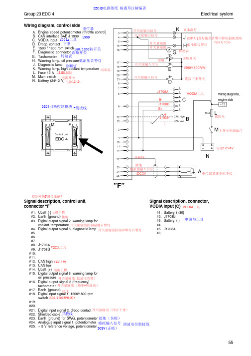
J. Heating element (does not function without the air pre-heating relay) 加热塞
K. Battery (24/12 V). 电池DC12/24V L. Connector, air pre-heater/coolant level
DEC4引擎控制模块 F侧接线
开关量输出信号 开关量输出信号
开关量输出 开关量输出
接地 开关量输入信号
开关量输入信号
J1708A BJ1708B B+ H J1939 L
Electrical system
高水温灯 诊断灯(黄灯衡量告警不停机辅助故障 有闪灯代码 低油压告警灯
转速表 诊断开关 1500/1800R/M
Group 23 EDC 4
DEC4D电路图纸 杨遇草注解编著
Wiring diagram, control side 电位器
A. Engine speed potentiometer (throttle control) B. CAN interface SAE J 1939 1939 C. VODIA input VDOIA工具 D. Droop contact 下垂 E. 1500 / 1800 rpm switch150/1800转开关 F. Diagnostic connector 诊断开关 G. Tachometer 转速表 H. Warning lamp, oil pressure低油压告警灯 J. Diagnostic lamp 诊断灯 K. Warning lamp, high coolant temperature 高水温 L. Fuse 15 A 15ABA保险 M. Main switch 主电源开关 N. Battery (24/12 V).电池12/24
- 1、下载文档前请自行甄别文档内容的完整性,平台不提供额外的编辑、内容补充、找答案等附加服务。
- 2、"仅部分预览"的文档,不可在线预览部分如存在完整性等问题,可反馈申请退款(可完整预览的文档不适用该条件!)。
- 3、如文档侵犯您的权益,请联系客服反馈,我们会尽快为您处理(人工客服工作时间:9:00-18:30)。
Issuer (dept., name, phone, location, sign.) Date2003-11-03Appendix Insert Registration No.SubjectCAN Frames -EDC4 Category Uncontr.Reciever (name, dept., location)The CAN - BUS has the following adjustment:The node address of EDC4 is 0.The rate of transmission is 250 kBaudAfter switching power on EDC4 waits 10 sec for the other nodes before the time out diagnostic starts.During the 10 second after switching power on a receive message must be received 4 times at least, other wise there will be a time out error.When the power supply drops below 9Volt, EDC4 will admit the other nodes a time out of 30sec.A receive message can be missing 8 times in a row before a time out Error willbe generated.1. If a message of Torque Speed Control has generated the time out, theLimp Home Function will be started. If the message will be receivedagain it will not be accepted anymore by the EDC4 until the EDC4 isrestarted again.2. In case of other receive messages that generated a time out the lastreceived value will be used. If a message is received again it will beaccepted automatically.The node address for the received messages are 3. Only the request and engine stop request messages can be received from any node on the BUS. The priority, resolution, repetition rate and all other information is outlined in the CAN Specification for EDC4.Issuer (dept., name, phone, location, sign.) Date2003-11-03Appendix Insert Registration No.SubjectCAN Frames -EDC4 Category Uncontr.Receive Messages.TSC1ID: 0C 00 00 03Byte 1 Control Bits SAE J1939/71, Parameter3.3.1Bit 1, 2 Override control modeBit 3, 4 Requested speed control condition ( notused)Bit 5, 6 Override control priority (not used)Bit 7, 8 Not definedByte 2,3 Requested speed / speed limit 0,125 rpm /Bit Byte 4 Requested torque / torque limit 1% /Bit, -125%OffsetByte 5-8 Not definedOverride Control Mode:00 no changes, the last mode will be usedBytes 2 to 8 will be ignored.01 set speed control, using bytes 2 and 3 for requested speedByte 4 will be ignoredno limits will be changed10 torque control mode, using byte 4 for requested torqueBytes 2 and 3 will be ignoredno limits will be changed11 setlimitsBytes 2 and 3 are the limit of speed control.Byte 4 contents the limit for torque controlPriority Bits00 HighestPriority01 HighPriority10 LowPriority11 LowestPriorityIssuer (dept., name, phone, location, sign.) Date2003-11-03Appendix Insert Registration No.SubjectCAN Frames -EDC4 Category Uncontr.DM3 Delete Passive ErrorID: 18 FE CC 03DM3:Transmission rate: if requiredData length: 0 BytesData Page: 0PDUF: 254 PDUS: 204 Priority: s. Appendix 5 Parameter groupnumber:65228 (00FECC)Source Address: External Device Nr.ID:DM11 Delete active ErrorID: 18FE D3 03DM11:Transmission rate: if requiredData length: 0 BytesData Page: 0PDUF: 254 PDUS: 211 Priority: s. Appendix 5 Parameter groupnumber:65235 (00FED3)Source Address: External Device Nr.ID:Issuer (dept., name, phone, location, sign.) Date2003-11-03Appendix Insert Registration No.SubjectCAN Frames -EDC4 Category Uncontr.Engine stop requestID: 08 FF 16 xxTransmission rate: s. Appendix 5Data Length: 1 BytesData Page: 0PDUF: 255PDUS: 22Priority: s. Appendix 5Parameter groupnumber:00FF16Source Address: external Device Nr.ID:Byte 1 Engine stopEngine stop = 1 the engine will be stoppedEngine stop ≠ 1 the engine will not be stopped by this commandDM5 RequestID: 18 EA 00 xxEDC4 receives this messages as a request to send the number of faults, which have occurred once at least and are active or passive at that moment. Transmission rate: If requiredData Length: 3 BytesIssuer (dept., name, phone, location, sign.) Date2003-11-03Appendix Insert Registration No.SubjectCAN Frames -EDC4 Category Uncontr.Transmit MessagesEEC1ID: 0C F0 04 00Transmission rate:Data Length: 8 BytesData Page: 0PDUF: 240PDUS: 4Priority: s. Appendix 5Parameter group number: 61444Source Address: Device-Nr. EDC4Byte 1 Status8 =engine is working at limited torque(max. torque curve)3 = engine speed governor is active14 = engine torque control ( min. max.governor) is activeByte 2 Requested engine torque in %related to Md max1%/Bit, -125% OffsetByte 3 Engine torque related toMd max1%/Bit, -125% OffsetByte 4-5 Engine speed 0,125 rpm /BitByte 6-8 Not definedThe value of Byte 3 is the actual engine torque in percent of the reference engine torque of the message engine configuration.The torque values of Byte 3, TSC1 and the points 1 to 5 of the message engine configuration are directly comparable to each other because of the same reference value.Issuer (dept., name, phone, location, sign.) Date2003-11-03Appendix Insert Registration No.SubjectCAN Frames -EDC4 Category Uncontr.EEC2ID: 0C F0 03 00Transmission rate: s. Appendix 5Data Length: 8 BytesData Page: 0PDUF: 240PDUS: 3Priority: s. Appendix 5Parameter group number: 61443Source Address: Device Nr. EDC4Byte 1 Status not defined (FF)Byte 2 Pedal position 0,4 %/BitByte 3 Engine torque related to maxengine torque at engine speed0,4 %/BitByte 4-8 Not definedThe value of Byte 3 is the actual engine torque in percent of the maximum available engine torque at the actual engine speed.Fuel EconomyID: 18 FE F2 00Data Length: 8 BytesData Page: 0PDUF: 254PDUS: 242Priority: s. Appendix 5Parameter group number: 65266 (00FEF2 H)Source Address: Device Nr. EDC4ID:Byte 1-2 Fuel rate 0,05 L/h /BitByte 3,4 Instantaneous fuel economy km/lByte 5-8 Not definedIssuer (dept., name, phone, location, sign.) Date2003-11-03Appendix Insert Registration No.SubjectCAN Frames -EDC4 Category Uncontr.Engine TemperatureID: 18 FE EE 00Data Length: 8 BytesData Page: 0PDUF: 254PDUS: 238Priority: s. Appendix 5Parameter group number: 65262 (00FEEE H)Byte 1 Coolant temperature 1°C /Bit, -40 °C Offset Byte 2 Fuel temperature 1°C /Bit, -40 °C Offset Byte 3 not available (FF)Byte 4 not available (FF)Byte 5-8 Not definedInlet/Exhaust ConditionsID: 18 FE F6 00Data Length: 8 BytesData Page: 0PDUF: 254PDUS: 246Priority: s. Appendix 5Parameter group number: 65270 (00FEF6 H)Byte 1 Not definedByte 2 Boost pressure 2 kPa/Bit = 1/50 bar/BitByte 3 Intake manifoldtemperature1°C /Bit, -40 °C OffsetByte 4-8 Not definedIssuer (dept., name, phone, location, sign.) Date2003-11-03Appendix Insert Registration No.SubjectCAN Frames -EDC4 Category Uncontr.Engine Fluid Level / PressureID: 18 FE EF 00Data Length: 8 BytesData Page: 0PDUF: 254PDUS: 239Priority: s. Appendix 5Parameter group number: 65263 (00FEEF H)Byte 1 Not definedByte 2 Not definedByte 3 Oil level 0.4%/Bit, 0% Offset Byte 4 Oil pressure 4 kPa/Bit, 1/25bar /Bit Byte 5,6 not available (FF)Byte 7 not available (FF)Byte 8 Coolant level 0.4%/Bit, 0% OffsetIssuer (dept., name, phone, location, sign.) Date2003-11-03Appendix Insert Registration No.SubjectCAN Frames -EDC4 Category Uncontr.Messured Data1ID: 18 FF 04 00Transmission rate: s. Appendix 5Data Length: 8 BytesData Page: 0PDUF: 255PDUS: 4Priority: s. Appendix 5Parameter groupnumber:00FF04Source Address: EDC4 Device Nr.Byte 1 reservedByte 2-3 Engine speed 0,125 rpm /BitByte 4 Boost pressure 2kPa/Bit = 1/50 Bar/Bit Byte 5 Pedal position 0 to 100% 0,4 % BitByte 6 Coolant temperature 1°C /Bit, -40 °C Offset Byte 7 Oil pressure 4 kPa/Bit = 1/25 Bar /Bit Byte 8 Can statusCan status0 Initialization after power on1 or2 engine not started, waiting for start3 engine starts (is cranking)4 engine has started, is running, waiting for Can messageswith speed or torque demand5 engine is running, CAN messages for speed or torque control used.6 CAN messages for speed or torque demand failed (time-out)EDC4 uses another input for set point values as a substitute, i.e. acceleratorpedal7 Engine start protection is activeIssuer (dept., name, phone, location, sign.) Date2003-11-03Appendix Insert Registration No.SubjectCAN Frames -EDC4 Category Uncontr.Messured Data2ID: 18 FF 12 00Data Length: 8 BytesData Page: 0PDUF: 255PDUS: 18Parameter groupnumber:FF12Source Address: EDC4 Device Nr.Byte 1 DroopByte 2-3 set point data engine speed, droopcalculatedByte 4 source of set point data engine speedByte 5, 6 engine speed, sensor 1Byte 7, 8 engine speed, sensor 2DroopDroop = (n max - n rated) / n rated * 100 %n = engine speed, resolution 1% /BitSet point data engine speed, droop calculatedThis is a data inside EDC4 after selection of the source of requested speed at the input of the speed governor, calculated with droop.0,125 rpm/bit ; 0 rpm offsetrange: 0 to 8031,875 rpmSource of set point data engine speed:This value shows, which signal is the source of the actual set point data.0 No set point data1 Pedal input ( Analog / PWM input)2 Hand throttle lever3 Errorvalueused4 TSC1.a5 reserved ( for TSC1.b)6 reserved ( forSAE-J1587 PID 91 accelerator pedal)7 Constant speed 18 Constant speed 29 Frozen engine speed (actual engine speed saved)10 Frozen engine speed (set point speed saved)11 special function ( hold)Issuer (dept., name, phone, location, sign.) Date2003-11-03Appendix Insert Registration No.SubjectCAN Frames -EDC4 Category Uncontr.13 special function ( max)14 reserved (for PTO)15 idle calibration mode16 reserved (for VP2 pedal data)Engine speed sensor 1, 2If there is no engine speed sensor 2 available, i.e. a vehicle speed sensor is mounted, then the value will be FFh.0,125 rpm/bit ; 0 rpm offsetrange: 0 to 8031,875 rpmMessured Data3ID: 18 FF 13 00Data Length: 8 BytesData Page : 0PDUF : 255PDUS: 19Parameter groupnumber:FF13Source Address: EDC4 Device Nr.Byte 1 Power reductionByte 2 Maximum available engine torque at currentspeedByte 3, 4 Maximum available engine speedByte 5, 6 Hold engine speedByte 7, 8 not availablePower reductionThis is the actual value of the power reduction, calculated by the internal engine protection functions and the CAN message engine protection. The limits set by the message TSC1 have no influence on this value.Resolution 1%.Range 0 to 100%The value of no power reduction is 100%Maximum available engine torque at current speedThe maximum available engine torque at current speed in percent of the actual torque curve.Issuer (dept., name, phone, location, sign.) Date2003-11-03Appendix Insert Registration No.SubjectCAN Frames -EDC4 Category Uncontr.Engine protection functions and CAN messages, i.e. TSC1, can limit this data to a lower value. In that case not 100% of torque is available.If there are no actual limitations or power reductions, the available engine torque is given by the torque curve. The value will be 100%, then.Resolution: 1%Range: 0% to 100%Maximal available engine speedThe maximum available engine speed varies because of engine protection functions and other CAN messages.Resolution: 1/8 rpmRange 0 to 8000 rpmHold engine speedIs one of the following data, depending on which data is actual used:Frozen engine speed (actual engine speed saved)Frozen engine speed (set point speed saved)If none of both data is actual used the value will be FFhMessured Data3ID: 18 FF 13 00Transmission rate: s. Appendix 5Data Length: 8 BytesData Page : 0PDUF : 255PDUS: 20Priority: s. Appendix 5Parameter groupnumber:FF14Source Address: EDC4 Device Nr.ID:Byte 1,2set point value fuel quantity 0,1 mm3 / Stroke / BitByte 3, 4 desired value fuel quantity for drive abilitymap0,1 mm3 / Stroke / BitByte 5,6actual rack position 0,01 mm / BitByte 7,8desired rack position 0,01 mm / BitIssuer (dept., name, phone, location, sign.) Date2003-11-03Appendix Insert Registration No.SubjectCAN Frames -EDC4 Category Uncontr.LimitationID: 0C FF 15 00Transmission rate: s. Appendix 5Data Length: 8 BytesData Page : 0PDUF : 255PDUS: 21Priority: s. Appendix 5Parameter groupnumber:00FF15Source Address: EDC4-Device Nr.ID:Byte 1 Active limitation 1Byte 2 Active limitation 2Byte 3 Actual torque mapByte 4 Engine speed limitByte 5 Engine torque limitByte 6 Source of power reductionByte 7 Engine stopByte 8 not definedActive limitation 1Bit 8 Max. torque curve reachedBit 7 Max. engine speed limit reached (Engine speed limit)Bit 6 Engine speed limit TSC1 reached ( TSC1 Engine speed limit) Bit 5 Engine torque limit TSC1 reached (TSC1 Engine torque limit) Bit 4 Power reduction activeBit 3 engine shutdown protection / start prevention activeBit 2 limp home function activeBit 1 Road speed limitation active (configured limit reached )A Bit will only be set, when EDC4 is actually working at the limit.If there is a limit set, but no operation parameter has reached this limit, the corresponding bit will not be set.Issuer (dept., name, phone, location, sign.) Date2003-11-03Appendix Insert Registration No.SubjectCAN Frames -EDC4 Category Uncontr.Active Limitation 2Bit 6-8 reservedBit 5 overrun conditionBit 4 smoke limitationBit 3 limitation by barometric pressureBit 2 reserved (= 0 because limitation of vehicle speed by receive messageSAE-J1587 PID74 not available)Bit 1 reserved (= 0 because receive message torque limitingSAE-J1587 PID 68not available)A Bit will only be set, when EDC4 is actually working at the limit.If there is a limit set, but no operation parameter has reached this limit, the corresponding bit will not be setActual torque mapThis is the number of the selected max. torque curve, even when the engine is actually not working at this limit1 max. torque curve 12 max. torque curve 23 max. torque curve 3Engine speed limit0 normal speed limit (configuration parameter)1 TSC1.a2 TSC1.b3 TSC1.c4 TSC1.dThis is the number of the actual lowest engine speed limit, even when the engine is actually not working at this limitEngine torque limit0 normal limitation by max. torque curve1 TSC1.a2 TSC1.b3 TSC1.c4 TSC1.d5 reserved (will not appear, because receive message torque limitingSAE-J1587 PID 68is not available)6 smokelimitationThis is the number of the actual lowest engine torque limit, even when the engine is actually not working at this limitIssuer (dept., name, phone, location, sign.) Date2003-11-03Appendix Insert Registration No.SubjectCAN Frames -EDC4 Category Uncontr.Source of power reduction0 = no power reduction1 = engine protection2 = oil pressure3 = intake manifold temperature4 = Coolant temperature5 = barometric pressureThe number of the signal that makes the highest reduction will be send in this byte.The engine must not actually work at the limit to get a value different from zero. It is sufficient that a limit is set.Example:Power reduction 20% of max. torque curve because of Coolant temperature is too high, that means 80% of power is available. The engine may work at 10% of max. power, but the value of the byte will be 4.Engine stop0 = no special engine stop, normal engine stop1 = Engine shutdown for engine protection2 = CAN Message Engine Stop Request3 = Oil pressure too low4 = Oil level too low5 = Coolant temperature too high6 = Coolant level too low7 = Intake manifold temperature8 = reserved ( SAE-J1587 command9 = reserved (for VP2 not available)The value of this byte shows the reason, why EDC4 has shutoff the engine.If more limitations in EDC4 exist than these bytes represent, than this list will be enlarged.Issuer (dept., name, phone, location, sign.) Date2003-11-03Appendix Insert Registration No.SubjectCAN Frames -EDC4 Category Uncontr.Vehicle Electrical PowerID: 18 FE F7 00Data Length: 8 BytesData Page: 0PDUF: 254PDUS: 247Parameter group number: 65271 (00FEF7 H)Source Address: Device Number EDC4Byte 1-6 not available (FF)Byte 7,8 switched battery power at the input ofEDC40,05 V/BitAmbient ConditionsID: 18 FE F5 00Data Length: 8 BytesData Page: 0PDUF: 254PDUS: 245Parameter group number: 65269 (00FEF5 H)Source Address: Device Number EDC4Byte 1 barometric pressure 0,5 kPa/Bit = 1/200 Bar/Bit Byte 2,3 not available (FF)Byte 4-8 not available (FF)Issuer (dept., name, phone, location, sign.) Date2003-11-03Appendix Insert Registration No.SubjectCAN Frames -EDC4 Category Uncontr.State of inputs 1ID: 18 FF 0A 00Data Length: 8 BytesData Page: 0PDUF: 255PDUS: 10Parameter groupnumber:00FF0ASource Address: EDC4 Device Nr.Byte 1 Digital, PWM 1 Pin F 18Byte 2 Digital 6, Analog 1 Pin F 24Byte 3 Digital 2, PWM 2 Pin F 21Byte 4 Digital 4 Pin F 19Byte 5 Digital 8, Analog3 Pin F 20Byte 6 Digital 3 Pin F 6Byte 7 Digital 5 Pin M 6Byte 8 Digital 7, Analog 2 Pin M24What is connected to the inputs depends on the respective application.Digital:0 = boolish 0100 = boolish 1PWM:range 0 to 100 %resolution 1% / bitAnalog:range 0 to 5V = 0 to 100resolution 0.05V / bitFF H = Information not available ( Not definedIssuer (dept., name, phone, location, sign.) Date2003-11-03Appendix Insert Registration No.SubjectCAN Frames -EDC4 Category Uncontr.State of inputs 2ID: 18 FF 17 00Transmission rate: s. Appendix 5Data Length: 8 BytesData Page: 0PDUF: 255PDUS: 23Priority: s. Appendix 5Parameter groupnumber:00FF17Source Address: EDC4 Device Nr.ID:Byte 1 Digital 9, analog4 Pin M21Byte 2 Digital 10/ vehicle speed Pin F7Byte 3 not availableByte 4 not availableByte 5 not availableByte 6 not availableByte 7 not availableByte 8 not availableWhat is connected to the inputs depends on the respective application. Digital:0 = boolish 0100 = boolish 1PWM:range 0 to 100 %resolution 1% / bitAnalog:range 0 to 5V = 0 to 100resolution 0.05V / bitFF H = Information not available ( Not defined)Issuer (dept., name, phone, location, sign.) Date2003-11-03Appendix Insert Registration No.SubjectCAN Frames -EDC4 Category Uncontr.State of Digital OutputsID: 18 FF 0B 00Data Length: 8 BytesData Page: 0PDUF: 255PDUS: 11Parameter groupnumber:00FF0BSource Address: EDC4-Device Nr.Byte 1 Diagnostic lamp Pin F 4Byte 2 Digital 7, engine speed Pin F 16Byte 3 Digital, PWM 1 Pin F 5Byte 4 Digital 2 Pin F 3Byte 5 Digital 4 Pin M 3Byte 6 Digital Output 5 Pin F 15Byte 7 Digital Output 3 Pin M 2Byte 8 Digital Output 6/ PWM2 Pin M 7What is connected to the outputs depends on the respective application. Digital:0 = boolish 0100 = boolish 1PWM:range 0 to 100 %resolution 1% / bitengine speed: 40rpm / bitFF H = Information not available ( Not defined)Issuer (dept., name, phone, location, sign.) Date2003-11-03Appendix Insert Registration No.SubjectCAN Frames -EDC4 Category Uncontr.Engine ConfigrationID: 18 FE E3 00Data Length: 28 BytesData Page: 0PDUF: 254PDUS: 227Parameter group number: 65251 (00FEE3 H)Source Address: Device Number EDC4ID:Bytes 1-28 according to 3.3.17 of SAE J1939/71Byte 1,2 Engine speed at idle ( point 1)Byte 3 Percent torque at idle ( point 1)Byte 4, 5 Engine speed ( point 2)Byte 6 Percent torque ( point 2)Byte 7, 8 Engine speed (point 3)Byte 9 Percent torque (point 3)Byte 10, 11 Engine speed ( point 4)Byte 12 Percent torque ( point 4)Byte 13, 14 Engine speed ( point 5)Byte 15 Percent torque ( point 5)Byte 16, 17 Engine speed at high idle, engine torque = 0 (point 6)Byte 18, 19 Gain(KP) / droop 1)Byte 20, 21 Reference engine torque (Nm) (maximum torque of enginetorque map)Byte 22 to 24 not definedByte 25 Minimum engine speed value for TSC1 messagesByte 26 Maximum engine speed value for TSC1 messagesByte 27 Minimum engine torque value for TSC1 messagesByte 28 Maximum engine torque value for TSC1 messagesThis message uses more than 8 data bytes, therefore the Multipacket Transport ProtocolIssuer (dept., name, phone, location, sign.) Date2003-11-03Appendix Insert Registration No.SubjectCAN Frames -EDC4 Category Uncontr.Active Faults ( DM1 )ID: 18 FE CA 00Data Length: variableData Page: 0PDUF: 254PDUS: 202Parameter groupnumber:65226 (00FECA)Source Address: EDC4 Device Nr.Byte 1 Lamp state (LS)Byte 2 Lamp state (LS) reserved =FFByte 3, 4 Suspect Parameter Number (SPN)Byte 5 Bit 6 to 8 SPNBit 1 to 5 Failure mode identifier (FMI)Byte 6 Bit 8 not definedBit 1 to 7 Occurrence counter (OC)Byte 7, 8 not definedEngine HoursID: 18 FE E5 00Data Length: 8 BytesData Page: 0PDUF: 254PDUS: 229Parameter group number: 65253 (00FEE5 H)Source Address: Device Nr. EDC4ID:Byte 1-4 Engine hours 0,05 h/Bit Byte 5-8 Not definedIssuer (dept., name, phone, location, sign.) Date2003-11-03Appendix Insert Registration No.SubjectCAN Frames -EDC4 Category Uncontr.Number of faults ( DM5 )ID: 18 FE CE 00Transmission rate: on requestData Length: 8 BytesData Page: 0PDUF: 254PDUS: 206Parameter groupnumber:65230 (00FECE)Source Address: EDC4 Device Nr.Byte 1 Number of active faultsByte 2 Number of passive faultsByte 3-8 Not definedFreeze Frame Parameter ( DM4 )ID: 18 FE CD 00Transmission rate: On RequestData lengthData Page: 0PDUF: 254PDUS: 205Priority: s. Appendix 5Parameter groupnumber:65229 (00FECD)Source Address: EDC4 Device Nr.ID:Byte 1 Number of the following data bytes(Length)= 20 = 14h Byte 2 to 5 Diagnostic Trouble Code (DTC)Byte 6,7 Not availableByte 8, 9 Engine speed 1/8 rpm/bit Byte 10 - 19 Not availableByte 20, 21 EDC4 specific Engine hours 0,05 h / BitIssuer (dept., name, phone, location, sign.) Date2003-11-03Appendix Insert Registration No.SubjectCAN Frames -EDC4 Category Uncontr.Passive Faults ( DM2 )ID: 18 FE CB 00Transmission rate: On RequestData length: 8 BytesData Page: 0PDUF: 254PDUS: 203Priority: s. Appendix 5Parameter groupnumber:65227 (00FECB)Source Address: EDC4 Device Nr.Byte 1 Lamp state (LS)Byte 2 Lamp state (LS) reserved = FFByte 3, 4 Suspect Parameter Number (SPN)Byte 5 Bit 6 to 8 SPNBit 1 to 5 Failure Mode Identifier (FMI)Multipacket TransportID: 18 EC FF 00If more then 8 data bytes must be send they have to be separated in different packets. The first message is the Broadcast Announce Message (BAM). After that the data packets will be send.BAM:Transmission rate: s. below.Data length: 8Data Page: 0PDUF: 236PDUS: 255Priority: 6Parameter groupnumber:60416Source Address: Device- Nr. EDC4ID:Byte 1 32Byte 2, 3 Number of used data bytes of allpackets without the byte of packetnumberByte 4 number of PacketsByte 5 reserved FFByte 6 to 8 Parameter group numberIssuer (dept., name, phone, location, sign.) Date2003-11-03Appendix Insert Registration No.SubjectCAN Frames -EDC4 Category Uncontr.Multipacket Transport ProtocolID: 18 EB xx 00Die …parameter group number“ and the transmission rate are the same as in the message specified, which data are transferred with the Multipacket Transport (i.e. DM 1, DM 2)The data packets:Transmission rate: see aboveData length: 8Data Page: 0PDUF: 235PDUS: External Device NrPriority: 6Parameter groupnumber:00EbxxhSource Address: Device- Nr. EDC4ID:Byte 1 Packet Nr.Byte 2 to 8 DataThere may be less than 8 useful data bytes in the last data packet, so the rest of the data bytes are set to FF. The External Device No. is global (255) if the message is send cyclically, else it is the Device No. of the device which made a request.Issuer (dept., name, phone, location, sign.) Date2003-11-03Appendix Insert Registration No.SubjectCAN Frames -EDC4 Category Uncontr.AckownedgementID: 18 E8 FF 00according to SAE-J1939-21Transmission rate: Once, after receiving a messagewhich needs an Acknowledge. Data length: 8 BytesData Page: 0PDUF: 232PDUS: 255Priority: 6Parameter groupnumber:59647 (E8FF)Source Address: EDC4 Device Nr.ID:Byte 1 0 for positive Acknowledge1 for negative AcknowledgeByte 2 to 5 not definedByte 6 to 8 parameter group number of themessage, which needs anAcknowledgeIssuer (dept., name, phone, location, sign.) Date2003-11-03Appendix Insert Registration No.SubjectCAN Frames -EDC4 Category Uncontr.AppendixAppendix 1: Multipacket TransportIf more then 8 data bytes must be send they have to be separated in different packets. The first message is the Broadcast Announce Message (BAM). After that the data packets will be send.BAM:Transmission rate: s. below.Data length: 8Data Page: 0PDUF: 236PDUS: 255Priority: 6Parameter groupnumber: 60416Source Address: Device- Nr. EDC4ID:Byte 1 32Byte 2, 3 Number of used data bytes of all packetswithout the byte of packet numberByte 4 number of PacketsByte 5 reserved FFByte 6 to 8 Parameter group numberThe …parameter group number“ and the transmission rate are the same as in the message specified, which data are transferred with the Multipacket Transport (i.e. DM 1, DM 2) The data packets:Transmission rate: see aboveData length: 8Data Page: 0PDUF: 235PDUS: External Device NrPriority: 6Parameter groupnumber: 00EbxxhSource Address: Device- Nr. EDC4ID:Byte 1 Packet Nr.Byte 2 to 8 DataIssuer (dept., name, phone, location, sign.) Date2003-11-03Appendix Insert Registration No.SubjectCAN Frames -EDC4 Category Uncontr.There may be less than 8 useful data bytes in the last data packet, so the rest of the data bytes are set to FF. The External Device No. is global (255) if the message is send cyclically, else it is the Device No. of the device which made a request.Issuer (dept., name, phone, location, sign.) Date2003-11-03Appendix Insert Registration No.SubjectCAN Frames -EDC4 Category Uncontr.Appendix 2: Lamp statusMalfunction Lamp statusconsist of 2 Bits with00 not active (not lightened)01 active (lightened)11 not definedBit 1,2 Engine Protection Lamp• is active, if a data is out of normal operating range, i.e. in warning range.• is not active, if the data value is coming back out of the warning range andis below the recovery limit.Bit 3,4 Warning Lampis active, if the diagnostic lamp of EDC4 is continuously lightened, otherwiseit is inactive. That means it is active not only if a data value is in the warningrange, it is also set, if an electronic part of the EDC4 System has a fault whichdoes not causes an automatically shut off of the engine, i.e. broken wire.Bit 5,6 Stop lampactive, if the EDC4 diagnostic lamp is blinking to show an critical fault.That means an engine shut off is necessary.Bit 7,8 Emission Related Lampnot defined in EDC4 (11)DM1 and DM2 have a second Byte for Lamp Status, but the contents are not specified (=FF)After switching power supply the EDC4 diagnostic lamp is lightened for a test, but the bits defined above will not be set active for that reason.。