Interface based HardwareSoftware Validation of a System-on-Chip
软件测试常用术语

软件【Software】:软件(software)是计算机中与硬件(hardware)相结合的一部分,包括程序(program)和文档(document)。
用一个等式表示为:软件=程序+文档。
其中,“程序”指的是能够实现某种功能的指令的集合,如C语言程序,Java程序等;“文档”指的是在软件开发、使用和维护过程中产生的图文集合,如《系统需求规格说明书》、《用户手册》、readme,甚至是一些软件市场宣传资料,包装文字和图形等。
【备注:软件测试绝不等同于程序测试,文档测试也是软件测试的一个重要组成部分。
通常,程序测试主要包括程序逻辑功能、界面、性能、易用性、兼容性、安装等的测试;文档测试主要包括文档内容和截图的校验,排版风格的检查,错别字的校验等】客户端/服务器【C/S】:C指的是客户端(Client),S指的是服务器端(Server),这种软件是基于局域网或互联网的,需要一台服务器来安装服务器端软件,每台客户端都需要安装客户端软件。
比如我们经常用的QQ、MSN和各种网络游戏就属于C/S结构的软件。
【备注:C/S结构的软件过去比较流行,但是不便于升级和维护,现在逐渐被B/S结构软件所取代】浏览器/服务器【B/S】:B指的是浏览器(Browser),S指的是服务器(Server),这种软件同样是基于局域网或互联网的,它与结C/S构软件的区别就在于,不需要安装客户端(client),只需要有IE 等浏览器,就可以直接使用。
比如搜狐、新浪等门户网站及163邮箱都属于B/S结构的软件。
【备注:B/S结构软件是现在软件的主流,与C/S结构软件相比,便于升级和维护,是测试的重点】缺陷【Bug/Defect】:软件的Bug指的是软件中(包括程序和文档)不符合用户需求的问题。
【备注:这个定义是判断一个软件问题是否是Bug个唯一标准】软件测试【Software Testing】:使用人工或自动手段,来运行或测试某个系统的过程。
TMCM-1021 硬件手册说明书

MODULE FOR STEPPER MOTORSTRINAMIC Motion Control GmbH & Co. KGHamburg, GermanyHardware Version V1.2HARDWARE MANUAL+ +TMCM-1021++U NIQUE F EATURES :Table of Contents1Features (3)2Order Codes (5)3Mechanical and Electrical Interfacing (6)3.1Size of Board (6)3.2Connectors (7)3.2.1Power, Communication and I/O Connector (8)3.2.2Motor Connector (8)3.3Power Supply (9)3.4Communication (10)3.4.1RS485 (10)3.5Inputs and Outputs (11)3.5.1Digital Inputs IN_0, IN_1, IN_2, IN_3 (11)3.5.2Outputs OUT_0, OUT_1 (12)4Reset to Factory Defaults (13)5On-board LED (13)6Operational Ratings (14)7Functional Description (15)8Life Support Policy (16)9Revision History (17)9.1Document Revision (17)9.2Hardware Revision (17)10References (17)1FeaturesThe TMCM-1021 is a single axis controller/driver module for 2-phase bipolar stepper motors with state of the art feature set. It is highly integrated, offers a convenient handling and can be used in many decentralized applications. The module can be mounted on the back of NEMA11 (28mm flange size) and has been designed for coil currents up to 0.7A RMS and 24V DC supply voltage. With its high energy efficiency from TRINAMIC’s coolStep™ technology cost for power consumption is kept down. The TMCL™ firmware allows for both, standalone operation and direct mode.M AIN C HARACTERISTICSHighlights-Motion profile calculation in real-time-On the fly alteration of motor parameters (e.g. position, velocity, acceleration)-High performance microcontroller for overall system control and serial communication protocol handling-For position movement applications, where larger motors do not fit and higher torques are not requiredBipolar stepper motor driver-Up to 256 microsteps per full step-High-efficient operation, low power dissipation-Dynamic current control-Integrated protection-stallGuard2 feature for stall detection-coolStep feature for reduced power consumption and heat dissipationEncoder-sensOstep magnetic encoder (max. 1024 increments per rotation) e.g. for step-loss detection under all operating conditions and positioning supervisionInterfaces-Up to 4 multi-purpose inputs (2 shared with outputs)- 2 general purpose outputs-RS485 2-wire communication interfaceSoftware-TMCL: s tandalone operation or remote controlled operation,program memory (non volatile) for up to 876 TMCL commands, andPC-based application development software TMCL-IDE available for free.Electrical and mechanical data-Supply voltage: +24V DC nominal (9… 28V DC)-Motor current: up to 0.7A RMS (programmable)Refer to separate TMCL Firmware Manual, too.TRINAMIC S U NIQUE F EATURES – E ASY TO U SE WITH TMCLstallGuard2™ stallGuard2 is a high-precision sensorless load measurement using the back EMF on thecoils. It can be used for stall detection as well as other uses at loads below those which stall the motor. The stallGuard2 measurement value changes linearly over a wide range of load, velocity, and current settings. At maximum motor load, the value goes to zero or near to zero. This is the most energy-efficient point of operation for the motor.Load [Nm]stallGuard2Initial stallGuard2 (SG) value: 100%Max. loadstallGuard2 (SG) value: 0Maximum load reached. Motor close to stall. Motor stallsFigure 1.1 stallGuard2 load measurement SG as a function of loadcoolStep ™coolStep is a load-adaptive automatic current scaling based on the load measurement via stallGuard2 adapting the required current to the load. Energy consumption can be reduced by as much as 75%. coolStep allows substantial energy savings, especially for motors which see varying loads or operate at a high duty cycle. Because a stepper motor application needs to work with a torque reserve of 30% to 50%, even a constant-load application allows significant energy savings because coolStep automatically enables torque reserve when required. Reducing power consumption keeps the system cooler, increases motor life, and allows reducing cost.00,10,20,30,40,50,60,70,80,9050100150200250300350EfficiencyVelocity [RPM]Efficiency with coolStepEfficiency with 50% torque reserveFigure 1.2 Energy efficiency example with coolStep2Order CodesTable 2.2 Order codesA cable loom set is available for this module:Table 2.5 Cable loom order code3Mechanical and Electrical Interfacing3.1Size of BoardThe board with the controller/driver electronics has an overall size of 28mm x 28mm in order to fit on the back side of a NEMA11 (28mm flange size) stepper motor. The printed circuit board outline is marked green in the following figure:PCB outlineR 2.5mmFigure 3.1 Board dimensions and position of mounting holes3.2ConnectorsThe TMCM-1021 has two connectors, an 8-pin power and input/output connector and a 4-pin motor connector (used to connect the attached motor).Power / Communication / IOs11MotorFigure 3.2 TMCM-1021 connectorsOverview of connector and mating connector types:Table 3.2 Connectors and mating connectors, contacts and applicable wire3.2.1Power, Communication and I/O ConnectorAn 8-pin CVIlux CI0108P1VK0-LF 2mm pitch single row connector is used for power supply, RS485 serial communication and additional multi-purpose inputs and outputs.Table 3.3 Power, communication and I/O connector3.2.2Motor ConnectorAn 4-pin CVIlux CI0104P1VK0-LF 2mm pitch single row connector is used for connecting the four motor wires to the electronics.Table 3.4 Motor connector3.3 Power SupplyFor proper operation care has to be taken with regard to power supply concept and design. Due to space restrictions the TMCM-1021 includes just about 20µF/35V of supply filter capacitors. These are ceramic capacitors which have been selected for high reliability and long life time. The module includes a 28V suppressor diode for over-voltage protection.C AUTION !Add external power supply capacitors!It is recommended to connect an electrolytic capacitor of significant size (e.g. 470µF/35V) to the power supply lines next to the TMCM-1021!Rule of thumb for size of electrolytic capacitor: In addition to power stabilization (buffer) and filtering this added capacitor will also reduce any power supply wires and the ceramic capacitors. In addition it will limit slew-rate of power supply stability problems with some switching power supplies.Do not connect or disconnect motor during operation!Motor disconnected / connected while energized. These voltage spikes might exceed voltage limits of power supply before connecting / disconnecting the motor.Keep the power supply voltage below the upper limit of 28V!Otherwise operating voltage is near the upper limit a regulated power supply is highly recommended. Please see also chapter 6, operating values.There is no reverse polarity protection!The transistors.TMCM-1021 V1.2 Hardware Manual (Rev. 1.02 / 2013-JUL-23)10 3.4Communication3.4.1RS485For remote control and communication with a host system the TMCM-1021 provides a two wire RS485 bus interface. For proper operation the following items should be taken into account when setting up an RS485 network:1.BUS STRUCTURE:The network topology should follow a bus structure as closely as possible. That is, the connection between each node and the bus itself should be as short as possible. Basically, it should be short compared to the length of the bus.termination resistor (120 Ohm)termination resistor (120 Ohm)Figure 3.5: Bus structure2.BUS TERMINATION:Especially for longer busses and/or multiple nodes connected to the bus and/or high communication speeds, the bus should be properly terminated at both ends. The TMCM-1021 does not integrate any termination resistor. Therefore, 120 Ohm termination resistors at both ends of the bus have to be added externally.3.NUMBER OF NODES:The RS485 electrical interface standard (EIA-485) allows up to 32 nodes to be connected to a single bus. The bus transceiver used on the TMCM-1021 units (SN65HVD3082ED) has just 1/8th of the standard bus load and allows a maximum of 256 units to be connected to a single RS485 bus.4.NO FLOATING BUS LINES:Avoid floating bus lines while neither the host/master nor one of the slaves along the bus line is transmitting data (all bus nodes switched to receive mode). Floating bus lines may lead to communication errors. In order to ensure valid signals on the bus it is recommended to use a resistor network connecting both bus lines to well defined logic levels. In contrast to the termination resistors this network is normally required just once per bus. Certain RS485 interface converters available for PCs already include these additional resistors (e.g. USB-2-485).terminationresistor(120 Ohm)RS485- / RS485BRS485+ / RS485AFigure 3.6 Bus lines with resistor network3.5 Inputs and Outputs3.5.1 Digital Inputs IN_0, IN_1, IN_2, IN_3The eight pin connector of the TMCM-1021 provides four general purpose inputs IN_0, IN_1, IN_2 and IN_3. The first two inputs have dedicated connector pins while the other two share pins with two general purpose outputs.All four inputs are protected using voltage resistor dividers together with limiting diodes against voltages below 0V (GND) and above +3.3V DC (see figure below).IN_0IN_1IN_2IN_3microcontroller and TMC262Figure 3.7 General purpose inputsThe four inputs have alternate functionality depending on configuration in software. The following functions are available:Table 3.5 Multipurpose inputs / alternate functionsAll four inputs are connected to the on-board processor and can be used as general purpose digital inputs.Using the alternate functionality of IN_0 and IN_1 it is possible to control the on-board stepper motor driver with the help of an external stepper motor controller using step and direction signals. For the step and direction signals the signal levels are the same as for the general purpose digital inputs.IN_3 can be used as analog input, also. A 12bit analog to digital converter integrated in the microcontroller will convert any analog input voltage between 0 and +6.6V to a digital value between 0 and 4095 then.3.5.2Outputs OUT_0, OUT_1The eight pin connector of the TMCM-1021 provides two general purpose outputs. These two outputs are open-drain outputs and can sink up to 100mA each. The outputs of the N-channel MOSFET transistors are connected to freewheeling diodes each for protection against voltage spikes especially from inductive loads (relais etc.).Both outputs OUT_0 and OUT_1 share pins with two of the four inputs (IN_2 resp. IN_3).Please take into account the 20k (2x 10k in series) resistance to ground (transistor not active) of the input voltage divider (figure 4.8) when designing the external “load” circuit.OUT_0 / IN_2OUT_1 / IN_3microcontrollerFigure 3.8 General purpose outputs4Reset to Factory DefaultsIt is possible to reset the TMCM-1021 to factory default settings without establishing a communication link. This might be helpful in case communication parameters of the preferred interface have been set to unknown values or got accidentally lost.For this procedure two pads on the bottom side of the board have to be shortened (see Figure 4.1).Please perform the following steps:1.Power supply off and USB cable disconnected2.Short two pads as marked in Figure 4.13.Power up board (power via USB is sufficient for this purpose)4.Wait until the on-board red and green LEDs start flashing fast (this might take a while)5.Power-off board (disconnect USB cable)6.Remove short between pads7.After switching on power-supply / connecting USB cable all permanent settings have been restoredto factory defaultsShort these two padsFigure 4.1 Reset to factory default settings5On-board LEDThe board offers one LED in order to indicate board status. The function of the LED is dependent on the firmware version. With standard TMCL firmware the green LED flashes slowly during operation.When there is no valid firmware programmed into the board or during firmware update the green LED is permanently on.Green LEDFigure 5.1 On-board LED6Operational RatingsThe operational ratings show the intended or the characteristic ranges and should be used as design values. In no case shall the maximum values be exceeded!Table 6.1 General operational ratings of module*) maximum setting for prototype and first versions of TMCL firmware. Will be adapted in firmware for series version.Table 6.2 Operational ratings of multi-purpose I/OsTable 6.3 Operational ratings of RS485 interface7Functional DescriptionThe TMCM-1021 is a highly integrated controller/driver module which can be controlled via RS485 interface. Communication traffic is kept low since all time critical operations (e.g. ramp calculations) are performed on board. The nominal supply voltage of the unit is 24V DC. The module is designed for both, standalone operation and direct mode. Full remote control of device with feedback is possible. The firmware of the module can be updated via the serial interface.In Figure 7.1 the main parts of the module are shown:-the microprocessor, which runs the TMCL operating system (connected to TMCL memory),-the power driver with its energy efficient coolStep feature,-the MOSFET driver stage, and-the sensOstep encoder with resolutions of 10bit (1024 steps) per revolution.9…Figure 7.1 Main parts of TMCM-1021The TMCM-1021 comes with the PC based software development environment TMCL-IDE for the Trinamic Motion Control Language (TMCL). Using predefined TMCL high level commands like move to position a rapid and fast development of motion control applications is guaranteed. Please refer to the TMCM-1021 Firmware Manual for more information about TMCL commands.8Life Support PolicyTRINAMIC Motion Control GmbH & Co. KG does not authorize or warrant any of its products for use in life support systems, without the specific written consent of TRINAMIC Motion Control GmbH & Co. KG.Life support systems are equipment intended to support or sustain life, and whose failure to perform, when properly used in accordance with instructions provided, can be reasonably expected to result in personal injury or death. © TRINAMIC Motion Control GmbH & Co. KG 2013Information given in this data sheet is believed to be accurate and reliable. However neither responsibility is assumed for the consequences of its use nor for any infringement of patents or other rights of third parties, which may result from its use.Specifications are subject to change without notice.All trademarks used are property of their respective owners.9Revision History9.1Document RevisionFigure 9.1 Document revision9.2Hardware RevisionFigure 9.2 Hardware revision10References[TMCM-1021] TMCM-1021 TMCL Firmware Manual [QSH2818-32-07-006] NEMA11 / 28mm bipolar stepper motor [QSH2818-51-07-012] NEMA11 / 28mm bipolar stepper motor [USB-2-485] USB-2-485 interface converter TRINAMIC manuals are available on .。
Cadence Allegro and OrCAD 17.2-2016 Installation G
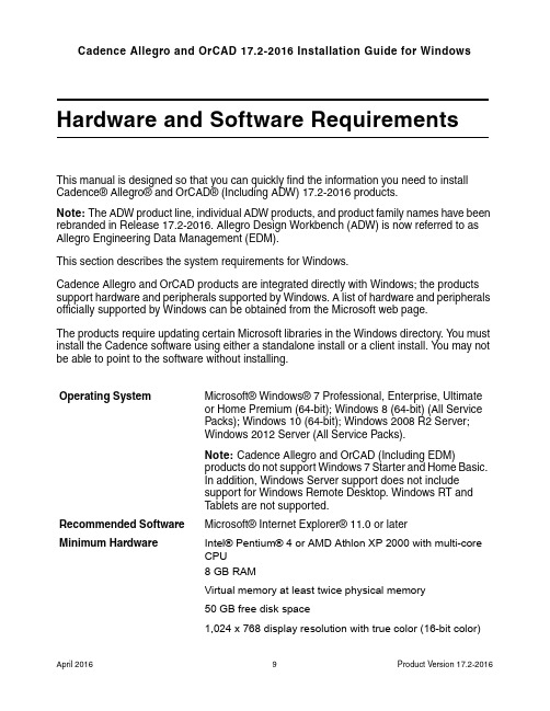
Hardware and Software RequirementsThis manual is designed so that you can quickly find the information you need to install Cadence® Allegro® and OrCAD® (Including ADW) 17.2-2016 products.Note: The ADW product line, individual ADW products, and product family names have been rebranded in Release 17.2-2016. Allegro Design Workbench (ADW) is now referred to as Allegro Engineering Data Management (EDM).This section describes the system requirements for Windows.Cadence Allegro and OrCAD products are integrated directly with Windows; the products support hardware and peripherals supported by Windows. A list of hardware and peripherals officially supported by Windows can be obtained from the Microsoft web page.The products require updating certain Microsoft libraries in the Windows directory. Y ou must install the Cadence software using either a standalone install or a client install. Y ou may not be able to point to the software without installing.Operating System Microsoft® Windows® 7 Professional, Enterprise, Ultimateor Home Premium (64-bit); Windows 8 (64-bit) (All ServicePacks); Windows 10 (64-bit); Windows 2008 R2 Server;Windows 2012 Server (All Service Packs).Note: Cadence Allegro and OrCAD (Including EDM)products do not support Windows 7 Starter and Home Basic.In addition, Windows Server support does not includesupport for Windows Remote Desktop. Windows RT andT ablets are not supported.Recommended Software Microsoft® Internet Explorer® 11.0 or laterMinimum Hardware Intel® Pentium® 4 or AMD Athlon XP 2000 with multi-coreCPU8 GB RAMVirtual memory at least twice physical memory50 GB free disk space1,024 x 768 display resolution with true color (16-bit color)Broadband Internet connection for some serviceEthernet card (for network communications and securityhostID)Three-button Microsoft-compatible mouseRecommended Hardware Intel® Core™ 2 Duo 2.66 GHz or AMD Athlon 64 X2 5200+Note: Faster processors are preferred.8 GB RAM500 GB free disk space1,280 x 1024 display resolution with true color (at least 32bitcolor)A dedicated graphics cardFor physical design dual monitorsBroadband Internet connection for some services Network Interface Cards (NICs)A network interface card (NIC) is the preferred locking method used in licensing to enable the products to run on a computer. Each NIC is programmed with an address that is sufficiently unique to enable its use as a hardware lock.Y ou can use the NIC in a laptop computer as your locking method, but you should be aware that in some laptops NICs are disabled if the laptops are not attached to a network. If your laptop’s NIC is disabled, you will not be able to run any products.DonglesIf your locking method is a dongle, attach the dongle to the appropriate parallel or USB port of the computer before you begin the installation. Click Cancel when the Windows generated Found New Hardware dialog appears. The dongle drivers will automatically install during the License Manager Installation.The following dongle is supported for Release 17.2-2016:■FLEXid USB dongle (version 9, flexid9)Cadence License FileIn order to run the Cadence Allegro and OrCAD products, you must have a valid license file (LICENSE.TXT) issued by Cadence.。
failure in the radio interface procedure 原因

failure in the radio interfaceprocedure 原因Failure in the Radio Interface Procedure: Causes and SolutionsA failure in the radio interface procedure can occur for various reasons, causing disruption in communication between mobile devices and the network. This article aims to explore the possible causes behind this issue and provide potential solutions to address them effectively.1. Network Congestion:One of the common reasons for a failure in the radio interface procedure is network congestion. When the network experiences high traffic or overloaded conditions, it can lead to interference and result in communication failure. This congestion can occur due to a surge in the number of users, inadequate network capacity, or insufficient resource allocation. To mitigate this issue, network operators need to invest in expanding network infrastructure and prioritize resources based on demand.2. Signal Interference:Signal interference can also be a factor contributing to a failure in the radio interface procedure. This interference can occur due to environmental factors such as physical obstacles, weather conditions, or electromagnetic interference from other devices. To minimize signal interference, operators should conduct regular site surveys to identify potential sources and take necessary measures to mitigate their impact, such as optimizing antenna placements or implementing shielding mechanisms.3. Hardware or Software Glitches:Faulty hardware or software within the mobile device or network equipment can lead to failures in the radio interface procedure. This may include malfunctioning antennas, out-of-date firmware, or incompatible software configurations. Regular maintenance andsoftware updates are crucial to keep the network infrastructure and mobile devices in optimal condition. Additionally, thorough testing before deploying any updates or new equipment can help identify and rectify potential glitches.4. Coverage Issues:Insufficient network coverage in certain areas can result in a failure in the radio interface procedure. This may include dead zones or areas with weak signal strength. Network operators need to conduct accurate coverage analysis and, if required, deploy additional base stations or repeaters to enhance signal coverage. Additionally, implementing technologies like beamforming or using higher frequency bands can help improve coverage in challenging areas.5. Authentication or Encryption Errors:Issues with authentication or encryption protocols can lead to a failure in the radio interface procedure. These errors are typically associated with incorrect configuration or compatibility issues between the mobile device and the network. Ensuring that devices and network equipment adhere to standardized protocols and regularly updating security measures can help minimize authentication or encryption errors.In conclusion, a failure in the radio interface procedure can arise from network congestion, signal interference, hardware or software glitches, coverage issues, or authentication/encryption errors. By investing in network expansion, conducting regular maintenance, optimizing signal coverage, and ensuring adherence to standardized protocols, network operators can mitigate these issues and provide a smoother and more reliable communication experience for users.。
微小米 Cortex-M1 启用 ProASIC3L 开发套件中 Core8051s 微控制器系统的

Application Note AC427July 20141© 2014 Microsemi Corporation Loading and Debugging Core8051s Application From External Flash MemoryTable of ContentsPurposeThis application note describes how to load and debug application code from external flash memory available on the Microsemi ® Cortex-M1-enabled ProASIC3L Development Kit.IntroductionA Core8051s based microcontroller system is implemented on the Microsemi M1 enabled ProASIC3L field programmable gate array (FPGA). The external flash memory is interfaced to the Core8051s microcontroller system to load and debug the application code.ReferencesThe following references are used in this document:•Core8051s Based Hardware Tutorial •Core8051s Based Software User GuidePurpose . . . . . . . . . . . . . . . . . . . . . . . . . . . . . . . . . . . . . . . . . . . . . . . . . . 1Introduction . . . . . . . . . . . . . . . . . . . . . . . . . . . . . . . . . . . . . . . . . . . . . . . . 1References . . . . . . . . . . . . . . . . . . . . . . . . . . . . . . . . . . . . . . . . . . . . . . . . 1Design Requirements . . . . . . . . . . . . . . . . . . . . . . . . . . . . . . . . . . . . . . . . . . 2Design Overview . . . . . . . . . . . . . . . . . . . . . . . . . . . . . . . . . . . . . . . . . . . . . 2Design Description . . . . . . . . . . . . . . . . . . . . . . . . . . . . . . . . . . . . . . . . . . . . 3Running the Design Example . . . . . . . . . . . . . . . . . . . . . . . . . . . . . . . . . . . . . . 13Conclusion . . . . . . . . . . . . . . . . . . . . . . . . . . . . . . . . . . . . . . . . . . . . . . . 22Appendix A – Design and Programming Files . . . . . . . . . . . . . . . . . . . . . . . . . . . . . 22List of Changes . . . . . . . . . . . . . . . . . . . . . . . . . . . . . . . . . . . . . . . . . . . . . 23Loading and Debugging Core8051s Application From External Flash Memory2Design RequirementsDesign OverviewA Core8051s IP based microcontroller system is developed with peripheral IPs such as CoreGPIO,CoreUARTapb, CoreWatchdog, CoreTimer, and CoreAPB3 that are implemented on the Microsemi Cortex-M1-enabled ProASIC3L Development Kit . An external Micron JS28F640J3D-75 flash memory is interfaced to the Core8051s microcontroller system. A simple application is loaded into the external Micron JS28F640J3D-75 flash memory to blink the on-board LEDs. Figure 1 shows the Core8051s microcontroller system.Table 1 • Design RequirementsDesign RequirementsDescriptionHardware RequirementsCortex-M1-enabled ProASIC3L Development Kit-Host PC or LaptopAny 64-bit Windows Operating System Software RequirementsLibero ® System-on-Chip (SoC)v11.3SoftConsolev3.4One of the following serial terminal emulation programs:• HyperTerminal• TeraTerm• PuTTY -Figure 1 • Core8051s Microcontroller SystemDesign Description3Design DescriptionThis design example has the following IPs that are available in Libero SoC catalog:•Core8051s : an 8-bit microcontroller IP core •CoreGPIO : provides up to 32-bit inputs and 32-bit outputs for general purpose •CoreUARTapb : a serial communication interface •CoreWatchdog : provides a means of recovering from software crashes •CoreTimer : for interrupt-generation and programmable counter •CoreAPB3: a bus component that provides advanced microcontroller bus architecture (AMBA3)advanced peripheral bus (APB3) fabric supporting up to 16 APB slavesThe following sections provide a brief description of each IP and its configuration:•Core8051s Description•Difference Between Core8051s and Core8051•CoreAPB3 Description•External Flash Memory Description•CoreTimer Description•CoreWatchdog Description•CoreUARTapb Description•CoreGPIO Description•Description of Core8051s based Microcontroller System•Memory Map•Software Development Description Core8051s DescriptionThe Core8051s is a high-performance, 8-bit microcontroller IP core. It is an 8-bit embedded controller that executes all ASM51 instructions and has the same instruction set as 80C31. It provides software and hardware interrupts. It eliminates redundant bus states and implements parallel execution of fetch and execution phases. The Core8051s uses one clock per cycle, and most of the one byte instructions are performed in a single clock cycle. Figure 2 shows the Core8051s architecture.Difference Between Core8051s and Core8051The Core8051s is smaller and more flexible than the Core8051.The microcontroller-specific features such as SFR-mapped peripherals, power management circuitry, serial channel, I/O ports and timers of the original 8051 are not present in Core8051s. The Core8051s contains the main 8051 core logic, but it does not have peripheral logic. The Core8051s has an advanced peripheral bus interface that can be used like the SFR (special function register) bus to easily expand the functionality of the core by connecting it to the existing advanced peripheral bus IPs. The Core8051s allows to configure the coreFigure 2 • Core8051s ArchitectureLoading and Debugging Core8051s Application From External Flash Memory4with the peripheral functions (timers, UARTs, I/O ports, etc.) that are required for the application.Configure the Core8051s Configurator GUI as shown in Figure 3.Refer to the Core8051s Handbook for more details.CoreAPB3 DescriptionThe CoreAPB3 is a bus component that provides advanced microcontroller bus architecture (AMBA3)advanced peripheral bus (APB3) fabric supporting up to 16 APB slaves, and a single APB master. The CoreAPB3 can be used with an APB3 master that does not have a built-in APB address decoding, such as Core8051s. A single APB3 master is connected to CoreAPB3. The master’s PSEL and PADDR signals are used within the CoreAPB3 to decode the appropriate PSELS slave select signals, and only one signal can be active at a time. This address decoding depends on the RANGESIZE hardware parameter/generic. Refer to the CoreAPB3 Handbook for more information.Figure 3 • Core8051s Configurator GUIDesign Description5Configure the CoreAPB3 Configurator GUI as shown in Figure 4.External Flash Memory DescriptionPart Number:•Micron JS28F640J3D-75Architecture: •64 Mbit (64 blocks)Performance: •75 ns Initial Access Speed, 25 ns 8-word and 4-word Asynchronous page-mode reads •32-Byte Write buffer (4 μs per Byte Effective programming time)System voltage: •VCC = 2.7 V to 3.6 V and VCCQ = 2.7 V to 3.6 V Enhanced security options for code protection:•128-bit Protection Register (64-bits unique device identifier bits, 64-bits user-programmable OTP (one time programmable) bits)•Absolute protection with VPEN = GND •Individual block locking •Block erase/program lockout during power transitions Figure 4 • CoreAPB3 Configurator GUILoading and Debugging Core8051s Application From External Flash Memory6Software:•Program and erase suspend support•Flash data integrator (FDI)•Common flash interface (CFI) compatibleThe external flash memory device can be accessed as 8- or 16-bit words. A command user interface (CUI) serves as the interface between the system processor and the internal operation of the device. A valid command sequence written to the CUI that initiates the device automation. An internal write state machine (WSM) automatically executes the algorithms and timings necessary for block erase, program, and lock-bit configuration operations.Flash operations are command-based, where command codes are first issued to the flash memory, then the flash memory performs the required operation. Refer to the flash memory Micron JS28F640J3D-75 datasheet for a list of command codes and flowcharts. Flash memory has a read-only 8-bit status register that indicates the flash memory status and operational errors. Four types of data can be read from the flash memory: array data, device information, CFI data, and device status.The flash memory is set to Read Array mode by default after power-up or reset. Executing the Read Array command sets the flash memory to Read Array mode and reads the output array data. The flash memory remains in Read Array mode until a different read command is executed. To change the flash memory to Read Array mode while it is programming or erasing, first issue the suspend command. After suspending the operation, run the Read Array command to set to Read Array mode. When the program or erase operation is subsequently resumed, the flash memory automatically sets to Read Status mode. Issuing the Read Device Information command places the flash memory in Read Device Information mode and reads the output of the device information. The flash memory remains in Read Device Information mode until a different read command is issued. Also, performing a program, erase, or block-lock operation changes the flash memory to Read Status Register mode.Array programming is performed by first issuing the single-word/byte program command. This is followed by writing the desired data at the desired array address. The read mode of the device is automatically changed to Read Status Register mode, which remains in effect until another read-mode command is issued.Erasing a block changes zeros to ones. To change ones to zeros, a program operation must be performed. Erasing is performed on a block basis - an entire block is erased each time when an erase command sequence is issued. Once a block is fully erased, all addressable locations within that block read as logical ones (FFFFh). Only one block-erase operation can occur at a time, and it is not allowed during a program suspend. To perform a block-erase operation, issue the block erase command sequence at the required block address. An erase or programming operation can be suspended to perform other operations, and then subsequently resumed. To suspend an on-going erase or a program operation, issue the suspend command to any address.All blocks are unlocked at the factory. Blocks can be locked individually by issuing the set block lock bit command sequence to any address within a block. Once locked, blocks remain locked when power cable is unplugged or when the device is reset. All locked blocks are unlocked simultaneously by issuing the clear block lock bits command sequence to any device address. The locked blocks cannot be erased or programmed.The sequence of the commands that must be given to the flash memory are written in an XML file. The XML files are provided with the SoftConsole software for the JS28F640J3D-75 flash memory located at: C:\Program Files (x86)\Microsemi\SoftConsole v3.4\Sourcery-G++\share\sprite\flash.Design Description7CoreTimer DescriptionThe CoreTimer is an APB slave that provides a functionality for the interrupt generations, and a programmable decrementing counter. It is configurable and programmable, and can be used in either continuous or one-shot modes. It is an essential element in many designs because it supports accurate generation of timing for precise application control. Refer to the CoreTimer Handbook for more information. Configure the CoreTimer Configurator GUI as shown in Figure 5.CoreWatchdog DescriptionThe CoreWatchdog is an APB slave that provides a means of recovering from software crashes. When the CoreWatchdog is enabled, the core generates a soft reset if the microprocessor fails to refresh it on a regular basis. The CoreWatchdog can be configured based on a decrementing counter, which asserts a reset signal if it is allowed to time out. The width of the decrementing counter can be configured as either 16 or 32-bits. The processor-accessible registers in CoreWatchdog provide a means to control and monitor the operation of the core. Refer to the CoreWatchdog Handbook for more information.Configure the CoreWatchdog Configurator GUI as shown in Figure 6.Figure 5 • CoreTimer Configurator GUIFigure 6 • CoreWatchdog Configurator GUILoading and Debugging Core8051s Application From External Flash Memory8CoreUARTapb DescriptionThe CoreUARTapb is a serial communications interface that is primarily used in the embedded systems.The controller can operate in either an asynchronous (UART) or a synchronous mode. In asynchronous mode, the CoreUARTapb can be used to interface directly to industry standard UARTs. The CoreUARTapb has an APB-wrapper that adds an APB interface allowing the core to be connected to the APB bus and controlled by an APB bus master. Unlike a standard 8051 UART, the CoreUARTapb includes a baud rate generator and so does not need a separate timer for the baud rate. Refer to the CoreUARTapb Handbook for more information.Configure the CoreUARTapb Configurator GUI as shown in Figure 7.Figure 7 • CoreUARTapb Configurator GUIDesign Description9CoreGPIO DescriptionThe CoreGPIO is an APB bus peripheral that provides up to 32-bit inputs and 32-bit outputs for general purpose. Refer to the CoreGPIO Handbook for more information.Configure the CoreGPIO Configurator GUI as shown in Figure 8.Figure 8 • CoreGPIO Configurator GUILoading and Debugging Core8051s Application From External Flash Memory10Description of Core8051s based Microcontroller System All the peripherals are interfaced to the Core8051s as shown in Figure 9.Refer to the Core8051s Based Hardware Tutorial for more information.Figure 9 • SmartDesign Top-Level Block DiagramDesign Description Instantiate a two port RAM on the SmartDesign top-level and configure it as shown in Figure10.Figure 10 • SRAM ConfigurationExternal memory buffer and multiplexer are configured as shown in Figure11 and Figure12.Figure 11 • External Memory Buffer ConfigurationLoading and Debugging Core8051s Application From External Flash MemoryMemory MapRight-click the Modify Memory Map to see the memory map as shown in Figure 13.Software Development DescriptionThe drivers are generated from firmware catalog for CoreTimer, CoreGPIO, CoreWatchdog, CoreTimer,and hardware abstraction layer (HAL). The HAL is used by drivers to access the hardware and also allows the control of interrupts.Refer to the Core8051s Based Software User Guide for more information.The Core8051s hardware design provides access to the external flash memory and internal SRAM. The Core8051s flash programming flow for Core8051s program memory is similar to the existing programming flow for Cortex-M1 flash program memory. The principal difference is, instead of specifying the location, size and the type of the program memory in a linker script, the program memory details are given in a text file (a memory-region-file) which uses the same syntax as the memory command section of a GCC linker script. The SoftConsole project configuration must be modified to specify the memory-region-file as an argument to the actel-map.exe helper program. Application code is written in main.c of the SoftConsole project to blink the on-board LED's.Figure 12 • Multiplexer ConfigurationFigure 13 • Memory MapRunning the Design ExampleRunning the Design ExampleTo run the design example,1.Download the design example at,/download/rsc/?f=Core8051s_ExtFlashIntSRAM_DF2.Double-click the Program Device under Program Design to program the Cortex-M1-enabledProASIC3L Development Kit in the Design Flow window, as shown in Figure14.Figure 14 • Program DeviceLoading and Debugging Core8051s Application From External Flash Memory3.Open the SoftConsole project after successfully programming the device, as shown in Figure15.Figure 15 • SoftConsole Project WindowRunning the Design Example4.Right-click the Core8051s_ExtFlashIntSRAM on the left pane and click Properties, as shown inFigure16. The Properties window is displayed as shown in Figure16.Figure 16 • Project Properties5.Double-click Settings under C/C++ Build on the left pane of Properties window.Loading and Debugging Core8051s Application From External Flash Memory6.Click Tools Settings tab on the right pane and select the Memory map generator, as shown inFigure 17.7.Enter actel-map -M../intel-28f640-1x8-code-memory.txt text in the Command field.Note:The “intel-28f640-1x8” XML file, which is at C:\Program Files (x86)\Microsemi\SoftConsolev3.4\Sourcery-G++\share\sprite\flash is used for loading and debugging the JS28F640J3D-75 flash memory.Figure 17 • Memory Map GeneratorRunning the Design Example8.Right-click Core8051s_ExtFlashIntSRAM on the left pane and click Debug As > DebugConfigurations…, as shown in Figure18. The Debug Configurations window is displayed.Figure 18 • Debug ConfigurationsLoading and Debugging Core8051s Application From External Flash Memory9.Right-click Microsemi Core8051s Target and click New to create a new debug configuration, asshown in Figure19.Figure 19 • New Debug Configuration10.Click Debug.Figure 20 • Debug ConfigurationsRunning the Design Example After launching the debug session, the flash programming operation starts. The erase and writeoperations are shown in Figure21.Figure 21 • Flash ProgrammingLoading and Debugging Core8051s Application From External Flash Memory11.Start PuTTY (with settings 57600 baud rate, 8 data bits, and No parity), and choose Resumefrom the Run menu. The LEDs are scanned on the Cortex-M1-enabled ProASIC3L Development Kit in the forward and reverse direction. The messages are displayed as shown in Figure 22.12.Terminate and relaunch the debug session.13.Set break points at 60, 115 and 149 lines of main.c.14.Choose Resume from the Run menu.15.Choose Step Over from the Run menu until it reaches the 115 line of main.c. The “RunningCore8051s Application from External Flash Memory” message is displayed as shown in Figure 23.Figure 22 • Application Running From External Flash MemoryFigure 23 • Debug CodeRunning the Design Example2116.Choose Step Over from the Run menu. While stepping over the code, the LEDs blinks on theMicrosemi Cortex-M1-enabled ProASIC3L Development Kit . The message is displayed as shown in Figure 24.Figure 24 • Step OverLoading and Debugging Core8051s Application From External Flash Memory2217.Right-click Core8051s_ExtFlashIntSRAM Debug [Microsemi Core8051 Target] and clickTerminate and Remove the debug session as shown in Figure 25.18.Choose Exit from the File menu to close the SoftConsole project.19.Unplug the USB cables and power supply cable and plug-in the power supply cable. The sameLED scanning application runs from the non-volatile external flash memory.ConclusionThis application note describes how to load and debug the Core8051s application from the external flash memory using SoftConsole. The example design serves as a starting point to other Core8051s designs.It includes a Core8051s based system, firmware drivers, and a sample LED scanning application that runs from the external flash memory.Appendix A – Design and Programming FilesYou can download the design files from the Microsemi SoC Products Group website:/download/rsc/?f=Core8051s_ExtFlashIntSRAM_DFThe design file consists of Libero project and programming file. Refer to the Readme.txt file included in the design file for directory structure and description.Figure 25 • Terminate and Remove Debug SessionList of Changes 23List of ChangesThe following table lists the critical changes that were made in the current version of the application note.DateChanges Page Revision 1(July 2014)Initial Release.NA51900295-1/7.14© 2014 Microsemi Corporation. All rights reserved. Microsemi and the Microsemi logo are trademarks of Microsemi Corporation. All other trademarks and service marks are the property of their respective owners.Microsemi Corporate HeadquartersOne Enterprise, Aliso Viejo CA 92656 USA Within the USA: +1 (800) 713-4113 Outside the USA: +1 (949) 380-6100Sales: +1 (949) 380-6136Fax: +1 (949) 215-4996E-mail:***************************Microsemi Corporation (Nasdaq: MSCC) offers a comprehensive portfolio of semiconductor and system solutions for communications, defense and security, aerospace, and industrial markets. Products include high-performance and radiation-hardened analog mixed-signal integrated circuits, FPGAs, SoCs, and ASICs; power management products; timing and synchronization devices and precise time solutions, setting the world's standard for time; voice processing devices; RF solutions; discrete components; security technologies and scalable anti-tamper products; Power-over-Ethernet ICs and midspans; as well as custom design capabilities and services. Microsemi is headquartered in Aliso Viejo, Calif. and has approximately 3,400 employees globally. Learn more at .。
软件名称说明书

Application•Automatic report generation, printout, data readout, data storage, protected export, PDF document generation •Generation of reports and templates•Readouts via online interface or from mass storage/ data carrier•SQL database - tamper-proof data storage•Online visualization of instantaneous values ("live data")•Export/import of data•Report generation for predefined standard reports or report templates generated in accordance with customer requirements•The following versions of the software are available: Essential version (free of charge), Professional Demo version and Professional version (optionally available with report function). It is possible to switch to the Professional version at any time by entering a valid license key.Your benefits•Reliable process documentation•Intuitive user guidance and modern interface •Highest safety through tamper-proof data storage and extensive user management functions•Reduced data management costs due to data archiving •Flexibility through SQL database•Central databaseProducts Solutions ServicesTechnical InformationField Data Manager SoftwareMS20PC analysis software for data management andvisualizationTI01022R/09/EN/05.1671315797Field Data Manager Software MS202Endress+HauserGeneral informationField Data Manager (FDM) is a software package that offers centralized data management with visualization for recorded data.This enables all measuring point data to be completely archived, e.g.:•Measured values •Diagnostic events •Analyses •Event logbookThe following versions of the software are available:•Essential version: This software version is available free of charge with restricted functionality.•Professional Demo version: The demo version has the full range of functionality but is valid for 90days only. After 90 days it is downgraded to the Essential version. The reporting option is not included in the demo version.•Professional version: This version has the full range of functionality and can be purchased using a licensing model.•Professional version with reporting: In addition to the functionality of the Professional version, it is possible to generate reports (based on the templates provided or in accordance with customer requirements).It is possible to switch from the Essential version and the Demo version to the Professional version at any time by entering a valid license key.FDM saves the data in an SQL database. The database can be operated locally or in a network (client / server). The following databases are supported:•PostgreSQL™ (for Essential, Demo and Professional version): You an install and use the free PostgreSQL database provided on the FDM DVD.•Oracle™ (for Demo and Professional version): version 8i or higher. To set up user login, please contact your database administrator.•Microsoft SQL Server™ (for Demo and Professional version): version 2005 or higher. To set up user login, please contact your database administrator.Versions The following table shows the range of functionality of the different software versions:Field Data Manager Software MS20Endress+Hauser 3System requirements In order to install and operate the FMD software, the following hardware and software requirements must be met:Hardware requirements for FDM software:•PC with Pentium TM 4 (≥2 GHz)•PC with Pentium TM M (≥1 GHz)•PC with AMD TM (≥1.6 GHz)•Minimum 512 MB RAM cache •Minimum 1 GB free hard disk memory •Minimum screen resolution of 1024 x 800 pixel •CD/DVD driveHardware requirements for reporting server:•The installation of the reporting server (BPI dashboard) requires approx. 1 GB of hard disk memory. If additional report projects are uploaded, these files are also factored in, in which case they usually require only a few MB of hard disk memory.•The dashboard's Tomcat service requires approx. 1.5 GB of working memory. If the server is used only for reporting, 4 GB of working memory are sufficient. If it is used to run other applications,the memory requirement must be factored in.Field Data Manager Software MS204Endress+HauserOperating system/software for FDM software:•Microsoft TM Windows TM 2000 SP4•Microsoft TM Windows TM Server 2003 R2 SP2 Standard, Enterprise (32 Bit)•Microsoft TM Windows TM Server 2008 (32/64 Bit)•Microsoft TM Windows TM Server 2012 (64 Bit)•Microsoft TM XP SP2 (32 Bit)•Microsoft TM Vista TM (32/64 Bit)•Windows 7TM (32/64 Bit)•Windows 8TM (32/64 Bit)•Windows 10TM (32/64 Bit)•Windows TM .NET 2.0 SP1Operating system for reporting server:•Windows 7TM (64 Bit)•Microsoft TM Windows TM Server 2008 (64 Bit)•Microsoft TM Windows TM Server 2012 R2 (64 Bit)Ordering informationLicensing model The basic installation of the Professional version of the FDM software includes an interface to the SQL database and a Postgre™ SQL database as well as all main functions. In the Professional version with reporting option, report generation is also possible. If another supported SQL database (e.g. an already existing installation) is to be used, FDM can also be connected to the existing database. If the Professional version of the FDM software is to be installed on several workstations, one license is required per workstation .Ordering information Detailed ordering information is available from the following sources:•In the Product Configurator on the Endress+Hauser website: -> Click "Corporate"-> Select your country -> Click "Products" -> Select the product using the filters and search field ->Open product page -> The "Configure" button to the right of the product image opens the Product Configurator.•From your Endress+Hauser Sales Center:Product Configurator - the tool for individual product configuration •Up-to-the-minute configuration data •Depending on the device: Direct input of measuring point-specific information such as measuring range or operating language •Automatic verification of exclusion criteria •Automatic creation of the order code and its breakdown in PDF or Excel output format •Ability to order directly in the Endress+Hauser Online ShopOrder code Order code for Endress+Hauser Field Data Manager software:MS20-A1 (Professional version; 1x workstation license)MS20-A1+E1 (Professional version with reporting option; 1x workstation license)Demo version The Demo version can be used free of charge and without obligation for 90 days. The reporting option is not included in the Demo version. The current version of the Field Data Manager software can be found at: /ms20Updates Updates to the current version of the software are included in the purchase of the Professional version. The updates can be downloaded free of charge from /ms20. New versions of report projects are also made available here.Scope of deliveryA DVD with serial number and license key is dispatched with each license ordered. The license key is required when the software is installed for the first time.Field Data Manager Software MS20Endress+Hauser 5Supplementary documentation•System Components and Data Managers brochure (FA00016K/09)•Operating Instructions FDM "Field Data Manager Software" Online Help and Manual (BA00288R/09)•Brief Operating Instructions "Field Data Manager Software" (KA00466C/07)•Field Data Manager (FDM) – Energy Consumption Reports (CP01186R/11/EN)。
计算机主板图纸英语翻译及硬件 hardware 软件 software 网络 network

硬件 hardware 软件 software 网络 network一、硬件(hardware)主板 mainboard 或者 motherboard 显卡 graphics card 或者 display card磁盘 disk 硬盘 harddisk 软盘 softdisk 驱动器 drive光驱 cd/dvd-rom drive 刻录光驱cd-raw drive 电源 power 网卡 network interface card 简称 NIC 声卡 sound card 中央处理器 CPU center process unit 主机 host 鼠标 mouse 键盘 keyboard 显示器 displayer 或者 monitor设备 device 内存 memory 端口 port 中断 int 接口 interface 并行端口 LPT 串行端口 com 芯片 chip 计算机 computer 个人计算机或者电脑 pc打印机 printer 扫描仪 scanner 摄像头 cameras二、软件(software)程序 program 文件 file 文件夹 folder 系统 system 应用 application文档 document 设置 set 安装 setup 或者 install 卸载 uninstall退出 exit 或 quit 管理员 administrator 用户 user 加载或载入 load发送 send 共享 share 选择 select 驱动程序 driver 备份 backup复制 copy 粘贴 paste 剪切 cut 删除 delete 插入 insert 保存 save另存为 save as 编辑 edit 打印 print 查找 search 移动 move属性 property 打开 open 关闭 close 安全 security 工具 tool安全模式 safemodel 启动 boot 页面 page 病毒 virus 杀毒 kill virus查询 query 表单 table 追加 append 媒介 media 音量 volume重启 restart 或reboot 锁定 lock 格式化 format 分区 partition主引导记录 mbr 镜像 mirror 磁盘阵列 disk array 组 group 服务 sevice 桌面 desktop 运行 run 字体 font 屏幕 screen 地址 address 缓存 cacheram 读写存储器 rom 只读存储器 video 视频数据 data 检测 test 或 detect 访问 access 激活 active 配置 config 菜单 menu 标题 title 状态 status 三、网络 (network)调制解调器(俗称“猫”) modem 交换机 switcher 集线器 hub路由器 router 网卡 NIC局域网 local area network 简称 LAN城域网 metropolitan area network 简称 MAN广域网 WANWide Area Network 简称 WAN互联网 internet服务器 server 客户端 client 远程登陆 telnet 协议 potocol文件传输协议 file transfer protocol 简称 FTP超文件传输协议 hyper text transfer potocol 简称 HTTP简单传输协议 simple message transfer potocol 简称 SMTP传输控制协议 transmission control potocol 简称 TCP用户数据包协议 user datagram protocol简称 UDP动态域名服务器 dynamic domain server 简称 DNS动态主机配置服务器 dynamic host configuration potocol server 简称 DHCP无线 wireless 非屏弊双绞线 UTP 下载 download 上传 upload 连接connection通讯 communication 本地 local 远程 remote 网关 gateway 域名 domain 子网掩码 subnet mask 数据包 package 线路 line主板zhong3GIO(Third Generation Input/Output,第三代输入输出技术)ACR(Advanced Communications Riser,高级通讯升级卡)ADIMM(advanced Dual In-line Memory Modules,高级双重内嵌式内存模块)AGTL+(Assisted Gunning Transceiver Logic,援助发射接收逻辑电路)AHCI(Advanced Host Controller Interface,高级主机控制器接口)AIMM(AGP Inline Memory Module,AGP板上内存升级模块)AMR(Audio/Modem Riser;音效/调制解调器主机板附加直立插卡)AHA(Accelerated Hub Architecture,加速中心架构)AOI(Automatic Optical Inspection,自动光学检验)APU(Audio Processing Unit,音频处理单元)ARF(Asynchronous Receive FIFO,异步接收先入先出)ASF(Alert Standards Forum,警告标准讨论)ASK IR(Amplitude Shift Keyed Infra-Red,长波形可移动输入红外线)AT(Advanced Technology,先进技术)ATX(AT Extend,扩展型AT)BIOS(Basic Input/Output System,基本输入/输出系统)CNR(Communication and Networking Riser,通讯和网络升级卡)CSA(Communication Streaming Architecture,通讯流架构)CSE(Configuration Space Enable,可分配空间)COAST(Cache-on-a-stick,条状缓存)DASP(Dynamic Adaptive Speculative Pre-Processor,动态适应预测预处理器)DB: Device Bay,设备插架DMI(Desktop Management Interface,桌面管理接口)DOT(Dynamic Overclocking Technonlogy,动态超频技术)DPP(direct print Protocol,直接打印协议DRCG(Direct Rambus clock generator,直接RAMBUS时钟发生器)DVMT(Dynamic Video Memory Technology,动态视频内存技术)E(Economy,经济,或Entry-level,入门级)EB(Expansion Bus,扩展总线)EFI(Extensible Firmware Interface,扩展固件接口)EHCI(Enhanced Host Controller Interface,加强型主机端控制接口)EISA(Enhanced Industry Standard Architecture,增强形工业标准架构)EMI(Electromagnetic Interference,电磁干扰)ESCD(Extended System Configuration Data,可扩展系统配置数据)ESR(Equivalent Series Resistance,等价系列电阻)FBC(Frame Buffer Cache,帧缓冲缓存)FireWire(火线,即IEEE1394标准)FlexATX(Flexibility ATX,可扩展性ATX)FSB(Front Side Bus,前端总线)FWH(Firmware Hub,固件中心)GB(Garibaldi架构,Garibaldi基于ATX架构,但是也能够使用WTX构架的机箱)GMCH(Graphics & Memory Controller Hub,图形和内存控制中心)GPA(Graphics Performance Accelerator,图形性能加速卡)GPIs(General Purpose Inputs,普通操作输入)GTL+(Gunning Transceiver Logic,发射接收逻辑电路)HDIT(High Bandwidth Differential Interconnect Technology,高带宽微分互连技术)HSLB(High Speed Link Bus,高速链路总线)HT(HyperTransport,超级传输)I2C(Inter-IC)I2C(Inter-Integrated Circuit,内置集成电路)IA(Instantly Available,即时可用)IBASES(Intel Baseline AGP System Evaluation Suite,英特尔基线AGP系统评估套件)IC(integrate circuit,集成电路)ICH(Input/Output Controller Hub,输入/输出控制中心)ICH-S(ICH-Hance Rapids,ICH高速型)ICP(Integrated Communications Processor,整合型通讯处理器)IHA(Intel Hub Architecture,英特尔Hub架构)IMB(Inter Module Bus,隐藏模块总线)INTIN(Interrupt Inputs,中断输入)IPMAT(Intel Power Management Analysis Tool,英特尔能源管理分析工具)IR(infrared ray,红外线)IrDA(infrared ray,红外线通信接口,可进行局域网存取和文件共享)ISA(Industry Standard Architecture,工业标准架构)ISA(instruction set architecture,工业设置架构)K8HTB(K8 HyperTransport Bridge,K8闪电传输桥)LSI(Large Scale Integration,大规模集成电路)LPC(Low Pin Count,少针脚型接口)MAC(Media Access Controller,媒体存储控制器)MBA(manage boot agent,管理启动代理)MC(Memory Controller,内存控制器)MCA(Micro Channel Architecture,微通道架构)MCH(Memory Controller Hub,内存控制中心)MDC(Mobile Daughter Card,移动式子卡)MII(Media Independent Interface,媒体独立接口)MIO(Media I/O,媒体输入/输出单元)MOSFET(metallic oxide semiconductor field effecttransistor,金属氧化物半导体场效应晶体管)MRH-R(Memory Repeater Hub,内存数据处理中心)MRH-S(SDRAM Repeater Hub,SDRAM数据处理中心)MRIMM(Media-RIMM,媒体RIMM扩展槽)MSI(Message Signaled Interrupt,信息信号中断)MSPCE(Multiple Streams with Pipelining and Concurrent Execution,多重数据流的流水线式传输与并发执行)MT=MegaTransfers(兆传输率)MTH(Memory Transfer Hub,内存转换中心)MuTIOL(Multi-Threaded I/O link,多线程I/O链路)NCQ(Native Command Qu,本地命令序列)NGIO(Next Generation Input/Output,新一代输入/输出标准)NPPA(nForce Platform Processor Architecture,nForce平台处理架构)OHCI(Open Host Controller Interface,开放式主控制器接口)ORB(operation request block,操作请求块)ORS(Over Reflow Soldering,再流回焊接,SMT元件的焊接方式)P64H(64-bit PCI Controller Hub,64位PCI控制中心)PCB(printed circuit board,印刷电路板)PCBA(Printed Circuit Board Assembly,印刷电路板装配)PCI(Peripheral Component Interconnect,互连外围设备)PCI=E(PCI-Express)PCI SIG(Peripheral Component Interconnect Special Interest Group,互连外围设备专业组)PDD(Performance Driven Design,性能驱动设计)PHY(Port Physical Layer,端口物理层)POST(Power On Self Test,加电自测试)PS/2(Personal System 2,第二代个人系统)PTH(Plated-Through-Hole technology,镀通孔技术)RE(Read Enable,可读取)QP(Quad-Pumped,四倍泵)RBB(Rapid BIOS Boot,快速BIOS启动)RNG(Random number Generator,随机数字发生器)RTC(Real Time Clock,实时时钟)KBC(KeyBroad Control,键盘控制器)SAP(Sideband Address Port,边带寻址端口)SBA(Side Band Addressing,边带寻址)SBC(single board computer,单板计算机)SBP-2(serial bus protocol 2,第二代串行总线协协)SCI(Serial Communications Interface,串行通讯接口)SCK (CMOS clock,CMOS时钟)SDU(segment data unit,分段数据单元)SFF(Small Form Factor,小尺寸架构)SFS(Stepless Frequency Selection,步进频率选项)SLI(Scalable Link Interface,可升级连接界面)SMA(Share Memory Architecture,共享内存结构)SMT(Surface Mounted Technology,表面黏贴式封装)SPI(Serial Peripheral Interface,串行外围设备接口)SSLL(Single Stream with Low Latency,低延迟的单独数据流传输)STD(Suspend To Disk,磁盘唤醒)STR(Suspend To RAM,内存唤醒)SVR(Switching Voltage Regulator,交换式电压调节)THT(Through Hole Technology,插入式封装技术)UCHI(Universal Host Controller Interface,通用宿主控制器接口)UPA(Universal Platform Architecture,统一平台架构)UPDG(Universal Platform Design Guide,统一平台设计导刊)USART(Universal Synchronous Asynchronous Receiver Transmitter,通用同步非同步接收传送器)USB(Universal Serial Bus,通用串行总线)USDM(Unified System Diagnostic Manager,统一系统监测管理器)VID(Voltage Identification Definition,电压识别认证)VLB(Video Electronics Standards Association Local Bus,视频电子标准协会局域总线)VLSI(Very Large Scale Integration,超大规模集成电路)VMAP(VIA Modular Architecture Platforms,VIA模块架构平台)VSB(V Standby,待命电压)VXB(Virtual Extended Bus,虚拟扩展总线)VRM(Voltage Regulator Module,电压调整模块)WCT(Wireless Connect Technology,无线连接技术)WE(Write Enalbe,可写入)WS(Wave Soldering,波峰焊接,THT元件的焊接方式)XT(Extended Technology,扩充技术)ZIF(Zero Insertion Force, 零插力插座)芯片组ACPI(Advanced Configuration and Power Interface,先进设置和电源管理)AGP(Accelerated Graphics Port,图形加速接口)BMS(Blue Magic Slot,蓝色魔法槽)I/O(Input/Output,输入/输出)MIOC: Memory and I/O Bridge Controller,内存和I/O桥控制器NBC: North Bridge Chip(北桥芯片)PIIX: PCI ISA/IDE Accelerator(加速器)PSE36: Page Size Extension 36-bit,36位页面尺寸扩展模式PXB: PCI Expander Bridge,PCI增强桥QPI(Quick Path Interconnect,快速通道互联)RCG: RAS/CAS Generator,RAS/CAS发生器SBC: South Bridge Chip(南桥芯片)SMB(System Management Bus,全系统管理总线)SMT(Simultaneous Muti-hreading,同时多线程)SPD(Serial Presence Detect,连续存在检测装置)SSB: Super South Bridge,超级南桥芯片TDP: Triton Data Path(数据路径)TSC: Triton System Controller(系统控制器)QPA: Quad Port Acceleration(四接口加速)主板技术GigabyteACOPS: Automatic CPU OverHeat Prevention System(CPU过热预防系统)SIV: System Information Viewer(系统信息观察)磐英ESDJ(Easy Setting Dual Jumper,简化CPU双重跳线法)浩鑫UPT(USB、PANEL、LINK、TV-OUT四重接口)华硕C.O.P(CPU overheating protection,处理器过热保护)•VCC是主供电VDD是门电路供电中华维VID是CPU电压识别信号,以前的老主板有VID跳线,现在的一般都没有,CUP的工作电压就是VID来定义VCC就是电压,vid就是控制电源IC输出多大的电压给CPU,vtt是参考电压(有VTT1.5V、VTT2.5V)VTT是AGTL总线终端电压。
hacmp工作原理及安装

11
IBM HACMP双机系统的安装及配置(续)
五、具体配置
注:HACMP的配置(或修改配置)只需要在其中的一台主机上进行,当配置
(或修改)完毕后使用同步命令将配置结果传到另外一台主机上。一般选S85_1 在进行配置
#smitty tty TTY TTY type TTY interface Description Status Location
Parent adapter
tty0 tty rs232 Asynchronous Terminal
Available 20-70-01-00
sa2
10
IBM HACMP双机系统的安装及配置(续)
逻辑地看成一块大硬盘 物理分区(PP):卷组中物理卷划分成固定大小
的块(缺省为4MB) 逻辑卷(LV):逻辑卷是位于物理分区上的信息
集合 逻辑分区(LP):逻辑卷由一定数量的逻辑分区
组成
22
IBM磁盘阵列及文件系统的管理(续)
二、常用命令
lsvg rootvg 看内置硬盘属性
lsdev -Cc disk 看所有硬盘
(1) Cascading (2) Concurrent (3) Rotating
16
IBM HACMP双机系统的安装及配置(续)
3、配置Cluster Resources
3.1 定义一个资源组(Define Resource Groups)
注意,在定义资源组的时候,要注意Participating Node Names的先后顺序
- 1、下载文档前请自行甄别文档内容的完整性,平台不提供额外的编辑、内容补充、找答案等附加服务。
- 2、"仅部分预览"的文档,不可在线预览部分如存在完整性等问题,可反馈申请退款(可完整预览的文档不适用该条件!)。
- 3、如文档侵犯您的权益,请联系客服反馈,我们会尽快为您处理(人工客服工作时间:9:00-18:30)。
Interface based Hardware/Software Validation of a System-on-Chip Debashis Panigrahi,Clark N.Taylor and Sujit DeyDepartment of Electrical and Computer EngineeringUniversity of California,San Diegodpani,cntaylor,dey@AbstractThe availability of reusable IP-cores,increasing time-to-market and design productivity gap,and enabling deep sub-micron technologies have led to core-based system-on-chip(SoC)design as a new paradigm in electronic system design.Validation of these complex hardware/software sys-tems is the most time consuming task in the designflow.In this paper,we focus on developing an efficient interface-based validation methodology for core-based SoC designs.In SoCs designed with pre-validated IP cores,the verification complexity can be significantly alleviated by concentrating on the integration of the cores in the system, rather than the complete SoC.In this paper,we investigate typical interface problems that arise in integrating cores in a SoC,and classify these problems into different cate-gories.Based on the classification of these interface prob-lems,we introduce an interface-based validation methodol-ogy.Finally,we demonstrate the effectiveness of the pro-posed methodology using an example image compression SoC that we are developing.1.IntroductionThe growing demand for hardware/software systems,to-gether with the ability to put the entire system on a sin-gle chip using deep sub-micron technologies,has led to the evolution of complex hardware/software system-on-chips (SoCs).While the complexity of SoCs increases,so does the demand to reduce their time-to-market.Though the de-sign time of SoCs can be greatly reduced by efficient re-use of intellectual property(IP)cores,the validation of SoCs is still a complex and time consuming task.In this paper,we focus on developing an efficient validation methodology for IP core-based SoC designs.Any system validation framework can be characterized by three parameters,namely the validation methodology, the level of abstraction used for validation,and what needs to be validated.Figure1presents these parameters and the interdependency between them.For instance,traditionally the complete system is validated using hardware simulation models of the system components at varying levels of ab-straction,i.e.behavioral,register transfer,gate,and transis-tor.d at io ne bu gg i ngV al ioMe th od ol og yFigure1.Different dimensions of validationLately,several attempts have been made to reduce the complexity of system validation by simulating at higher lev-els of abstraction using efficient simulation methodologies. For instance,Hw/Sw co-simulation tools[1,3]reduce the validation time by performing simulation at higher levels of abstraction,specifically by using instruction accurate mod-els of processors.Interface based design methodology,pro-posed in[2],is another example of validation at a higher level of abstraction,which allows separating communica-tion between components from behavior of a system.In this methodology,the system can be simulated with differ-ent levels of abstraction of communication between com-ponents,initially starting with an abstract model,and us-ing refined models of communication between components in the successive phases of the design.While previously proposed methodologies for the validation of a SoC sig-nificantly decrease the simulation time through the use of higher levels of abstraction,simulation of the entire sys-tem is still required.As the complexity of SoCs rapidly in-creases with the use of heterogeneous and complex IP cores, simulating the entire system becomes prohibitively expen-sive,even with the use of abstract models for computation and communication.The problem is further compounded by the need for multiple iterations of system simulation to detect andfix design errors.The complexity of verifying a SoC can be significantly alleviated by(1)using pre-validated IP cores and(2)con-centrating on verifying the integration of the cores in the SoC,rather than attempting to verify the entire SoC.In-stead of simulating all the components of a SoC together, the interface between different components can be verified independently.Independent validation of the interfaces can substantially reduce the overall time spent in SoC valida-tion by pointing out the design problems early in the ver-ification cycle.Moreover,by dividing the integration pro-cedure methodically,and then simulating only the compo-nents necessary to validate the interface involved,we add another dimension for decreasing the design validation time required.In Figure1,we illustrate how our method applies to the other methods currently used to decrease the verifica-tion time.It is important to note that the proposed interface based simulation can be performed at any level of abstrac-tion(i.e.behavioral level,RT Level etc.)and using any simulation methodology(i.e.co-simulation,Communica-tion/Behavior simulation[2],hardware simulation).From our experiences in designing an image compres-sion SoC,we identify common interface problems in in-tegrating different components of a SoC.These interface problems can be classified into different categories based on their nature and scope.For example,the interface be-tween a component and a system bus should be validated before the communication between two components using the system bus is verified.Based on the classification of these integration problems,we propose an interface based validation methodology for core-based SoCs.For efficiently validating the interface between a hard-ware component and a software component,we designed a fast and accurate co-simulation environment.We use the co-simulation environment to implement the interface based validation methodology proposed.The rest of the paper is organized as follows.In section 2,we introduce the reconfigurable image compression SoC that we have designed and will use to illustrate various is-sues in the rest of the paper.We introduce and classify some common interface problems of SoC integration in section3. We also propose our interface based validation in this sec-tion.We present the co-simulation environment in section 4.The experimental results demonstrating the efficiency of the proposed methodology is presented in section 5.Sec-tion6concludes the paper.2.A System-on-Chip ArchitectureTo fully understand the issues involved in validating a SoC,we developed a reconfigurable image compression system-on-chip(SoC)for wireless multimedia applications. Using this SoC as an example,we illustrate the validation problems and procedures outlined in this paper.A brief de-scription of the architecture of the SoC follows.Figure2.Architecture of an image compres-sion System-on-ChipThe reconfigurable image compression SoC,shown in Figure2,includes a processor core,two hardware accelera-tors,an on-chip memory,timers,master/slave interfaces to external components,and an internal system bus.PicoJava, a soft processor core from SUN Microsystems[4],is used as the processor,while PI-BUS[5]is used for the system bus.The hardware accelerators are designed to implement the most compute-intensive portions of image compression algorithms,while the picoJava processor implements the more control-intensive,parameterizable portions of the al-gorithms.We have implemented as hardware accelerators two transforms,the discrete cosine transform(DCT)[6], and the discrete wavelet transform(DWT)[7].These trans-formations form the basis of image compression algorithms such as JPEG[8]and SPIHT[9].Additionally,the chip has a128KByte on-chip SRAM.In the next section,we point out some common interface problems with integrating cores into a SoC.We illustrate with some examples from our experiences in the validation of the image compression SoC.3.Problems in SoC Integration:Communica-tion Mechanisms&InterfacesAs discussed earlier,we view the main task in validating a core-based SoC as ensuring a proper interface between the cores.In this section,we present some common interface problems,and classify the problems so that the interfaces can be verified in a methodical way.Without loss of generality,a SoC consists of different types of components,such as hardware cores,processorcores running software,and/or programmable logic cores, and one or more communication architectures(CA)con-necting the components,as shown in Figure3.The com-munication architectures may consist of system buses,in-terrupt lines,and other dedicated communication interfaces between the components.For example,in our image com-pression SoC,the main components are the picoJava pro-cessor core,the DCT component,the DWT component,and the memory;while the PI-BUS,including the bus control unit,constitute a central communication architecture.The integration of components in a SoC involves design-ing proper physical interfaces and communication mecha-nisms between the components.The communication mech-anisms consist of both synchronization and dataflow be-tween components,and can be implemented in several ways.For example,synchronization between a HW com-ponent and a SW component can be implemented as(a) interrupt-based,where the HW component sends an inter-rupt to the SW component,or(b)polling-based,where the SW component polls a system memory address which is set by the HW component when the HW is ready to commu-nicate.All physical interfaces and communication mecha-nisms need to be verified in the validation process of a SoC.Next,we present some common integration problems, which can occur either in the physical interfaces or in the communication mechanisms.We have classified the prob-lems,and propose a verification methodology based on the classification.Figure3.A Generic Architecture of Hw/SwSoCInterface between Component and Communication ArchitectureThe interface between each component and the commu-nication architecture should be validated to ensure that the component can communicate to other components.Po-tential problems can arise when there is a mismatch be-tween the interface requirement of the component and the interface supported by the communication architecture. We classify these interface problems as Component-To-Communication(a)COMP2COMM Interface Validation(b)COMP2COMP Interface Validation(c)COMM InterfaceValidation(d)SYS Validation Figure4.Interface Validation of a SoCpicoJava having higher priority than the DCT component for access to the bus.The correct assignment of priorities should be validated in this step.Additionally,we faced some problems in validating the SoC because of an incorrect memory map in the bus con-trol unit.As reported earlier,the DCT component as well as the DWT component are memory-mapped components to the picoJava processor through the PI-BUS.While we had validated the interface between the picoJava processor and DCT component,and the picoJava processor and DWT component,independently during the COMP2COMP stage, we discovered an error when the picoJava processor,the DCT component and the DWT component were simulated together as the DCT component and the DWT component had overlapping memory maps in the bus control unit.The validation of the interfaces,as described in this sec-tion,verifies the communication between different com-ponents using relatively small test-benches.Because test-benches supply a small set of vectors and are generally designed to detect certain types of bugs,the validation steps already listed(COMP2COMM,COMP2COMP,and COMM)may not provide sufficient validation for a SoC design.Hence,for complete validation of the system,simu-lation of the entire system needs to be done,termed as SYS validation.However,the time consumed in the expensive step of complete system simulation can be drastically re-duced,if all interfaces have been validated a-priori.In this section,we presented some of the interface prob-lems and classified them into different groups based on their dependencies.Based on the classification of interface prob-lems,we propose a validation methodology in the next sub-section.3.1.Interface Based Validation MethodologyIn this subsection,we propose a verification methodol-ogy which verifies all the interfaces before the complete system level simulation is performed.We assume that the validation of all the components has already taken place (pre-validated cores).The steps of our validation methodology are shown in Figure 4.First,the COMP2COMM interface needs to be verified using a high level test-bench for the commu-nication architecture.The highlighted portion in Figure 4(a)shows the COMP2COMM interface validation.The COMP2COMP interfaces are validated next.In this case, a pair of components with the communication architec-ture is simulated for potential interface problems.The COMP2COMP validation is shown by the highlighted por-tion in Figure4(b).A fast co-simulation environment can be used to speed up the validation of the COMP2COMP in-terface between a software component and a hardware com-ponent.The COMM interface is validated next.In this case, the communication architecture,the interfaces and some ab-stract models of components can be used to verify the po-tential problems in the communication architecture.Fig-ure4(c)shows the components involved in this validation step.After all the interfaces are verified independently the whole system is simulated,as shown in Figure4(d).Thismethodology allows the designer to validate the interfaces between components before a complete system simulation is run,drastically reducing the simulation time required for verification.To efficiently co-validate software and hardware compo-nents,we developed a co-simulation environment for pico-Java based SoCs.We describe the co-simulation environ-ment in the next section.4.Co-simulation EnvironmentThe interface and communication mechanism between a software component and a hardware component can be val-idated by simulating the software component using a hard-ware simulation model of the processor.However,simula-tion using a processor hardware model can be prohibitively slow.As the processor core is pre-validated,hardware simulation can be avoided by using an abstract,Instruc-tion Accurate Simulator(IAS)model of the processor.In this section,we compare the simulation performance of an RTL hardware model of the picoJava processor with an IAS model.We also present a fast and efficient co-simulation environment,using the IAS model of the picoJava proces-sor core,for validating the Hw/Sw interface problems of picoJava based SoCs.Table1shows the time taken(ms)in simulating several test programs provided in the picoJava validation test suite [10],using RTL simulation as well as IAS based simulation. From the results in Table1,it can be seen that the IAS sim-ulation is several orders of magnitude faster than the RTL simulation.parison of IAS model with RTLmodelProgram IAS SimulationTime(ms)int 1.20dcu70.99fadd10934031 1.10push17.50 To efficiently use the IAS model of the picoJava proces-sor to validate the interface between software and hardware components,we developed a Hw/Sw co-simulation frame-work shown in Figure 5.In this framework,the software simulation uses the IAS model of the picoJava processor. For hardware simulation,rather than using a RTL model of the processor,a Fast Interface Model(FIM)is used for sim-ulating the interface of the processor with other components such as the bus interface,interrupts,and timers.However, the FIM hardware simulation must be synchronized with the IAS software simulation for correct Hw/Sw system simula-tion.An efficient co-simulation interface has been developed to synchronize between the software simulation(the IASFigure5.Co-validation Environment for a SoC model)and the hardware simulation(the FIM model). Whenever external memory is accessed in IAS,IAS sends the request to FIM using the co-simulation interface,which in turn initiates the read/write cycle on the bus and acknowl-edges back to IAS with the fetched data.Additionally, whenever the FIM gets an interrupt from other hardware components,it is communicated to IAS in software so that the software can execute the appropriate trap handler.The interfaces between a software component and other components in a picoJava based SoC can be verified very fast using this co-simulation environment as it avoids the time consuming hardware model simulation,and instead simulates only the interface of picoJava with other compo-nents in hardware.To show the effectiveness of the pro-posed co-simulation,we simulated the interface between the picoJava processor,the DCT component and the mem-ory component,using both RTL simulation as well as the co-simulation environment proposed.For a particular im-age(COWWEI)of size64x64pixels,the RTL simulation took12975seconds while the system simulation using the co-simulation environment took only138seconds.From this and other experimental results that we are getting,co-simulation environment gives nearly100X improvement in system simulation speed.5.Experimental ResultsIn this section,we demonstrate the effectiveness of the proposed verification methodology based on our experi-ments with the image compression chip presented in section 2.Some of the interface problems described earlier are in-troduced in the SoC design and the time required to validate the SoC is compared with other methodologies.We introduce in the SoC one error from each class of in-terface problems(called ERR1to ERR3).A possible way of validating the design would be to simulate the complete SoC using some input data(an image in our case).The row SYS in Table2corresponds to simulating the SoC with a particular image(CUTWEBEAST)of size128x128pixels using RTL simulation as well as co-simulation.Though co-simulation is significantly faster than RTL simulation,over-all validation time can be prohibitive since detecting an er-ror may need multiple such simulations.The rows ERR1to ERR3in Table2correspond to validation for detection the errors using interface-specific test-benches.Before com-menting on the results,we give a brief description of the errors considered in the design.ERR1is an interface problem between the PI-Bus and the memory unit,which is an example of a COMP2COMM problem.The PI-Bus expects the data and the data-ready signal at the same clock cycle.However,in the design with ERR1,an error was introduced in the physical inter-face between the memory and the PI-Bus,causing timing mismatch between the data and the data-ready signal.Another error,ERR2,is an interface problem of class COMP2COMP,between picoJava and the DCT unit.In the SoC design,the communication between picoJava and DCT is performed by a polling based mechanism where picoJava writes to an internal register to start the DCT processing.In ERR2the polling address of DCT and the address picoJava writes to are different,resulting in wrong functionality.As described earlier,the DCT and DWT components are memory mapped in the address space of picoJava.In ERR3, we consider an interface problem where there is an over-lap in the address space between the DCT component and the external memory.This is an interface problem of class COMM.We simulated each of the above errors using three differ-ent simulation methodologies:(1)complete system simu-lation at RT Level(RTL),(2)system simulation using co-simulation methodology described in section4(Cosim), and(3)the proposed interface based simulation(Interface). We report the CPU time(secs)required for validation using above simulation schemes in Table2.parison of Validation Time CaseCosimCOMP2COMM170.1 3.1COMP2COMP185.312.0 COMM197.015.2SYS32781.0-It can be seen from Table2that the proposed interface based validation methodology is very efficient infinding in-terface errors in the integration of components in a SoC. Firstly,detecting the interface errors by specifically target-ing them with interface specific test-benches(rows ERR1 to ERR3)takes significantly less time compared to simulat-ing the system with arbitrary image data(SYS).This shows that system validation time can be significantly reduced by initially targeting possible interface problems,like the ones presented in this paper.Secondly,while detecting any interface error,significant improvement in validation time can be achieved by just sim-ulating the required components instead of performing the complete system simulation.For example,to detect the er-ror ERR1,complete RTL simulation takes170.1secs,co-simulation takes19.2secs,where as the proposed inter-face based simulation takes3.1secs only,a performance improvement of6X over co-simulation and55X over RTL simulation.Similarly,in case of ERR2and ERR3,the in-terface based simulation is2X faster than the co-simulation and12X faster than RTL simulation.These improvements in simulation time become even more significant when the user has to perform the simulation multiple times tofind the errors.6.ConclusionIn this paper,we address the issue of validating complex core-based SoCs.From practical experience in designing a SoC,we identify several common problems in integration of components of a SoC,and classify them into general in-terface validation problems.We proposed a methodology to validate the communication mechanisms and physical inter-faces between the components before the complete valida-tion of the system is performed.Our experimental results demonstrate the significant reduction in validation time that can be achieved using our proposed methodology. References[1]Synopsys Eagle,/products/hwsw/hwsw.html.[2]J.A.Rowson and A.Sangiovanni-Vincentelli,“Interface-Based Design”,Proc.of Design Automation Conference, 1997[3]Mentor Graphics Seamless,http://www.mentorgraphics.com/codesign.[4]PicoJava Microprocessor Core,Sun Microsystems Inc,/microelectronics/picoJava/.[5]PI-Bus Toolkit,/engg/research/vlsi-Jan97/projects/pibus/.[6]N.Ahmed,T.Natrajan and K.R.Rao,“Discrete cosinetransformation”,IEEE Trans.on Computers,vol.23,pp.90-93,Jan1974.[7] A.Averbuch,zzar and M.Israli,“Image compressionusing wavelet transform and memtiresolution decomposi-tion”,IEEE Trans.on Image Processing,vol.5,pp.4-15, Jan1966.[8]G.K.Wallace“The JPEG still picture compression stan-dard”,Communications of the ACM,vol34,no4,pp30-44,1991.[9]Amir Sair and W.Pearlman,“A new fast and efficient imagecodec based on set partitioning in hierarchical trees”,IEEE Transactions on Circuits and Systems for Video Technology, vol.6,(no.3),pp.243-50,June1996.[10]PicoJava-II Verification Guide,Sun Microsystems,March1999。