Rockethybrid 1220
法尔肯9火箭成功完成热点火试验

部分 高速率 的数据 传输 需求 。 主机 应用 程序 不 断地 从伺 服控 制 卡读取 数据 ,利 用硬 件测 量法 测量 各种 传 输模 式 下的数 据传 输 率 ,测
得结 果如表 2所 示 。
f】 吴 国庆 ,现 代测 控技 术及 应用 f .北京 :电子工业 出版 社 ,2 0 . 4 M] 07 【】 陈康 , 5 王旭 东.基于 P I X 总线 的现 场装 备通 用检测 系统 设计 [1 E.航天 试
主机 应用 程 序不 断地 向伺 服控 制 卡发送 数 据 ,利 用硬 件 测量 法测 量各 种传 输模 式 下 的数据传 输 率 ,测
得 结果列 于表 1 。
表 1 主机 向伺服控制卡发送数据 的数据传输率
传输 方 式
从模 式 单周期 写
从模 式突 发写
单周期 写
总线 的伺 服控 制器 ,从而 实现 了将 各个 分系 统集 成在 同一个 P 机 箱 内 。 XI 主机 可 以通过 F GA创 建 的 R P AM 与 DS P进 行双 向通信 ,F G 内设 计 P I04本地 总 PA C 95 线控 制器 ,并且 在 F GA 内嵌 单 口 R M 。在 P I04 P A C 95
计划 在 3月 9 日进 行 ,但 当天 的 试 验 在进 入模 拟 倒 计 时后 由于 技 术 问题 而 被 迫 中止 。 S ae 公 司 C O 艾 伦 ・ 斯 克 3月 1 p cX E 马 1
有打开 。随着发射时序 问题的解决和静态点火试验的完成 ,未
来数周内法尔肯 9还将进行飞行 终止 系统 的最后~组试验 。如
导 弹 与 航 天 运 载 技 术
2 1 00
级 的定 时精 度 。但是 P I总线 的数据传 输率 快 ,要测 C 量主 机和 伺服 控制 卡 之 间的数 据传 输 率 ,毫秒 级 的定 时精度 不 能满足 要求 ,因此 本文采用 硬 件方法 来测 量 。
3D打印的下一代火箭发动机

3D 打印的下一代火箭发动机文/松堂▲ 3D 打印可以在发动机内部形成复杂的管路,这是传统制造很难做到的一般来说,如果要把两个用不同材料制成的零件结合在一起,就需要用 上焊接等手段,连接部分总是会存在机 械失效的风险,例如火箭发动机里用的点火器。
ASA 马歇尔飞行中心的科研人员 尝试着用3D 打印来解决这个问题。
他 们用辂银铁合金和铜锌合金材料,打印出了一种高25.4厘米、直径17.8厘米的部件。
用传统方法,这个部件要用4 个不同的部件铜焊在一起;而用3D 打 印,可以一次性解决。
制造完成后,这个点火器经历了33次测试,模拟了从首次点火到高空 二次点火的不同工况。
其中一次工作 了 10秒,其余都工作了 5秒;最低工作温度-1579,最高工作温度达到12049。
实验结束之后,阿拉巴马大学的研究人员把点火器纵向剖开,发现两种合金结合得很好,之间有一个相当大厚度的互扩散层,比传统的焊接工艺效果一点都不差。
马歇尔中心工程部的有一种说法认为,当人们拥有一 种新技术之后,初期往往用来做一些传统的工作。
当充分掌握之后,往往会发 明出全新的理念,对整个学科产生颠覆性的作用。
3D 打印技术就是其中的一个例子。
便宜了一半的发动机火箭发动机的结构复杂,零件外 形不规则,在传统的金属切削工艺下,有些零件的制造非常困难。
3D 打印首先用在了这些方面。
负责人认为,3D 打印技术至少能把未来发动机的制造成本降到今天的三分之—,制造周期减少一半。
事实证明,马歇尔中心的判断是 有道理的。
在美国主要发动机制造商之一的阿罗杰特公司,3D 打印技术的46 I SPACEEXPLORATION▲测试中的3D 打印发动机,火焰看上去很稳定▲ 3D 打印的发动机外观更加简洁引入让复杂零部件的制造工时减少了50%以上。
在联合发射联盟公司正在研制的“瓦尔肯”火箭中,上面级就打算采用 阿罗杰特公司的RL10C-X 发动机。
联合发射联盟公司多年来一直因为发射服务价格太高而为业界所诟病,因此在“瓦尔肯”的研制中,要求大幅度降低成本, 但不能影响到可靠性和性能。
朝鲜版“关岛快递”——“火星”12中远程弹道导弹

朝鲜版“关岛快递”——“火星”12中远程弹道导弹作者:陈泽慧来源:《坦克装甲车辆》 2017年第23期朝鲜在今年4月15日的“太阳节”阅兵式上首次公开亮相“火星”12中远程弹道导弹。
5月14日、8月29日和9月15日,朝鲜分别进行了“火星”12导弹的高弹道试验、低弹道试验和正常弹道试验。
导弹的实际飞行距离从787千米、2?700千米跨越到3?700千米,这三次试验为外界了解朝鲜导弹技术的发展水平提供了难得的资料。
发展概况“火星”12导弹首次亮相时曾被误认为是“火星”13(KN-08)导弹的改进型。
这是因为从外形上看,“火星”12的弹头设计与“火星”13导弹一模一样,相似的气动外形设计很容易让人感觉这是一枚去掉第三级的“火星”13。
在仔细观察这枚新导弹后,可以发现,“火星”12的电缆槽和加强肋并非像“火星”13那样一直延伸至弹体尾部,而是在离发动机底部喷口约1.7米处终止了,这意味着新导弹采用的不是像R-27潜射导弹或“火星”10/13那样的潜入式发动机设计,而是和“火星”5/6/7一样发动机舱与推进剂贮箱分开。
发动机安装在外形类似苏联SS-5导弹的筒裙体尾段内部,外部没有任何弹翼,尾段壳体上也开有便于使用操作的舱口。
“火星”12导弹的设计如同SS-5导弹的缩小版。
而朝鲜之所以能够研制出射程与SS-5/R-14导弹相当,但是重量却只有其三分之一多一点的“火星”12,原因就在于朝鲜开发出了比冲更高的新型液体火箭发动机。
值得一提的是,在此之前,朝鲜用来发射“光明星”系列卫星的“银河”3火箭的第一级弹体直径与SS-5导弹相当,不过即便是并联了4台“火星”7导弹发动机,由于其比冲较低,整体推力还是不如SS-5导弹。
而且即使在“银河”3火箭一级基础上开发射程覆盖关岛的新导弹,80吨左右的弹体重量也不利于在朝鲜多山地形条件下机动作战,庞大的弹体也更容易被敌方发现,生存力低下。
这也是朝鲜以高比冲的“火星”10发动机为基础开发弹体重量只有40吨左右的“火星”13洲际导弹的原因之一。
莫加 MPC-2121 系列 12英寸无风扇车辆面板计算机商品介绍说明书
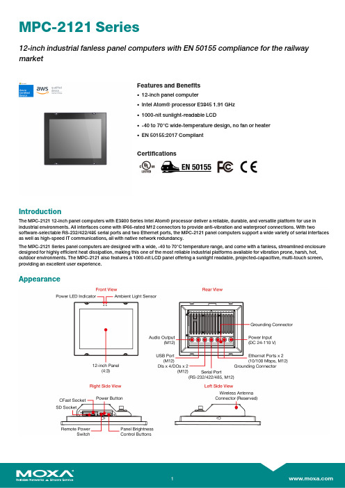
MPC-2121Series12-inch industrial fanless panel computers with EN50155compliance for the railway marketFeatures and Benefits•12-inch panel computer•Intel Atom®processor E38451.91GHz•1000-nit sunlight-readable LCD•-40to70°C wide-temperature design,no fan or heater•EN50155:2017CompliantCertificationsIntroductionThe MPC-212112-inch panel computers with E3800Series Intel Atom®processor deliver a reliable,durable,and versatile platform for use in industrial environments.All interfaces come with IP66-rated M12connectors to provide anti-vibration and waterproof connections.With two software-selectable RS-232/422/485serial ports and two Ethernet ports,the MPC-2121panel computers support a wide variety of serial interfaces as well as high-speed IT communications,all with native network redundancy.The MPC-2121Series panel computers are designed with a wide,-40to70°C temperature range,and come with a fanless,streamlined enclosure designed for highly efficient heat dissipation,making this one of the most reliable industrial platforms available for vibration prone,harsh,hot, outdoor environments.The MPC-2121also features a1000-nit LCD panel offering a sunlight readable,projected-capacitive,multi-touch screen, providing an excellent user experience.AppearanceSpecificationsComputerCPU Intel Atom®Processor E3845(2M Cache,1.91GHz)Graphics Controller Intel®HD GraphicsSystem Memory Pre-installed4(8GB Max.)GB DDR3LSystem Memory Slot SODIMM DDR3/DDR3L slot x1Pre-installed OS MPC-2121-E4-LB-CT-T-W7E/MPC-2101-E4-CT-T-W7E:Windows Embedded Standard7(WS7P)64-bit pre-installedMPC-2121-E4-LB-CT-T-LX/MPC-2121-E4-CT-T-LX:Linux9pre-installedSupported OS Windows10Pro64-bitWindows10Embedded IoT Ent2019LTSC64-bitWindows10Embedded IoT Ent2016LTSBWindows7Pro for Embedded SystemsWindows Embedded Standard7(WS7P)64-bitLinux Debian9Expansion Slots Mini PCIeStorage Slot CFast slot x1SD slots x1,SD3.0(SDHC/SDXC)socketStorage Pre-installed MPC-2121-E4-LB-CT-T-W7E/MPC-2121-E4-CT-T-W7E:32GB CFast CardMPC-2121-E4-LB-CT-T-LX/MPC-2121-E4-CT-T-LX:32GB CFast CardComputer InterfaceEthernet Ports Auto-sensing10/100Mbps ports(M12D-coded4P)x2Serial Ports RS-232/422/485ports x1(M12A-code12P)USB2.0USB2.0hosts x1(M12A-coded5P)Digital Input DIs x4(M12A-code)Digital Output DOs x2(M12A-code)LED IndicatorsSystem Power x1DisplayActive Display Area245.76(H)x184.32(V)mmAspect Ratio4:3Contrast Ratio1000:1Light Intensity(Brightness)500/1000cd/m2Max.No.of Colors16.2M(8-bit/color)Panel Size12-inch viewable imagePixel Pitch(RGB)0.240(H)x0.240(V)mmPixels1024x768Response Time5ms(gray to gray)Viewing Angles176°/176°Touch FunctionTouch Type Capacitive Touch(PCAP)Touch Support Points4pointsGlove Support YesSerial InterfaceBaudrate50bps to115.2kbpsData Bits5,6,7,8Flow Control RTS/CTS,XON/XOFFParity None,Even,Odd,Space,MarkStop Bits1,1.5,2Serial SignalsRS-232TxD,RxD,RTS,CTS,DTR,DSR,DCD,GND RS-422Tx+,Tx-,Rx+,Rx-,GNDRS-485-2w Data+,Data-,GNDRS-485-4w Tx+,Tx-,Rx+,Rx-,GNDPower ParametersInput Voltage24to110VDCPhysical CharacteristicsHousing MetalIP Rating IP66Dimensions297x238x59mm(11.69x9.37x2.32in) Weight2850g(6.28lb)Environmental LimitsOperating Temperature-40to70°C(-40to158°F)Storage Temperature(package included)-40to70°C(-40to158°F)Ambient Relative Humidity5to95%(non-condensing)Standards and CertificationsEMI CISPR32,FCC Part15B Class AEMS IEC61000-4-2ESD:Contact:6kV;Air:8kVIEC61000-4-3RS:80MHz to1GHz:20V/mIEC61000-4-4EFT:Power:2kV;Signal:2kVIEC61000-4-5Surge:Power:2kV;Signal:1kVIEC61000-4-6CS:10VIEC61000-4-8PFMFMechanical Protection Rating IEC60529,IP codeShock EN50155standardVibration EN50155standardEMC EN55032/35Safety IEC60950-1,IEC62368-1,UL62368-1 DeclarationGreen Product RoHS,CRoHS,WEEEWarrantyWarranty Period LCD:1yearSystem:3yearsDetails See /warrantyPackage ContentsDevice1x MPC-2121Series computerInstallation Kit6x screw,for panel-mounting1x M12-Phone jack power cable1x M12-Type A USB cable1x terminal block,2-pin(for remote power input) Documentation1x quick installation guide1x warranty cardDimensionsOrdering Information2.0MPC-2121-E4-LB-CT-T-W7E 12"(4:3)500nitsE3845Quadcore4GBW7E(64-bit)2(M12)1(M12)1(M12)4/2(M12)24to110VDCIP66-40to70°CMPC-2121-E4-CT-T-W7E12"(4:3)1,000nitsE3845Quadcore4GBW7E(64-bit)2(M12)1(M12)1(M12)4/2(M12)24to110VDCIP66-40to70°CMPC-2121-E4-LB-CT-T-LX 12"(4:3)500nitsE3845Quadcore4GB Debian92(M12)1(M12)1(M12)4/2(M12)24to110VDCIP66-40to70°CMPC-2121-E4-CT-T-LX12"(4:3)1,000nitsE3845Quadcore4GB Debian92(M12)1(M12)1(M12)4/2(M12)24to110VDCIP66-40to70°CMPC-2121-E4-LB-CT-T 12"(4:3)500nitsE3845Quadcore4GB–2(M12)1(M12)1(M12)4/2(M12)24to110VDCIP66-40to70°CMPC-2121-E4-CT-T12"(4:3)1,000nitsE3845Quadcore4GB–2(M12)1(M12)1(M12)4/2(M12)24to110VDCIP66-40to70°C©Moxa Inc.All rights reserved.Updated Jun28,2021.This document and any portion thereof may not be reproduced or used in any manner whatsoever without the express written permission of Moxa Inc.Product specifications subject to change without notice.Visit our website for the most up-to-date product information.。
世界航天新科技档案(一)各国新型火箭(中)

Frontier Research•前沿探索各国新型火箭世界航天新科技档案(一)(中)+刘进军“阿丽亚娜-6”火箭分为2种型号按照助推器的数量分为:“阿丽亚娜-6 2”、“阿丽亚娜-6 4”。
“阿丽亚娜-6 4”为重型火箭,设计有4个“P120”固体助推器,发射重量大约860吨。
“阿丽亚娜-6 4”“阿丽亚娜-6 2”为中型火箭,设计有2个“P120”固体助推器,发射重量530吨。
“阿丽亚娜-6 2”“阿丽亚娜-6”火箭主要参数高度 63米直径 5.4米质量 530吨~860吨级数2运载能力地球转移轨道阿丽亚娜-6 4:11.5吨阿丽亚娜-6 2:5吨地球静止轨道阿丽亚娜-6 4:5吨太阳同步轨道阿丽亚娜-6 4:14.9吨阿丽亚娜-6 2:6.45吨低轨道阿丽亚娜-6 4:21.65吨阿丽亚娜-6 2:10.35吨发射场圭亚那太空中心第一次飞行 2020 (计划)固体火箭助推器-推进器数量 2或4直径 3米推进剂质量 142吨发动机 P120推力 4500千牛芯级火箭–低温液体推进模块直径 5.4米推进剂质量 140吨发动机 火神-2推力 1370千牛燃料 液氢/液氧第2级–上部液体推进模块直径 5.4米推进剂质量31吨发动机 达芬奇推力 180千牛燃料液氢/液氧“阿丽亚娜-6”(Ariane-6)火箭是欧空局正在开发的运载火箭,由阿丽亚娜集团研制,研制费用36亿欧元。
它将成为“阿丽亚娜”运载火箭家庭新的成员,计划在2020年进行第一次试飞。
“阿丽亚娜-6”的运载能力可比肩美国“大力神-4”、“火神”,及日本“H-3”火箭。
“阿丽亚娜-6”重型火箭5图鉴世界航天新科技应用新技术:对比“阿丽亚娜-5”运输到发射台上之前采用的垂直组装、垂直运输和垂直点火的方法,“阿丽亚娜-6”火箭采用了水平组装、水平运输和垂直点火。
“阿丽亚娜-6”的主要箭体在新的综合组装厂水平组装,然后运往法属圭亚那太空中心。
在那里,它们将竖立起来,并与助推器和有效载荷结合。
惠威HR70遥控器使用说明书

HR070 Series Remote Control Programming Guide
6. Repeat steps 1 to 5 for the other components you want to control. For future reference, write down each working component code below:
HR Series Remote Control Programming
Assigned Push-button Component Program Code
TV
CBL
SAT
AUX
DVR
Push-buttons available for Programming
Flashes during Programming
4
Used to activate Programming Mode
with the most popular code first. If the component
responds, go to step 7.
6. If the component does not respond, press LEVEL+
Push-button and the Remote Control will test
The HR70 Series Remote Controls have stored in permanent memory the necessary information to send the correct commands to the component to be controlled. By entering a five digit numeric code the commands for controlling the component is activated.
H-IIA系列运载火箭

收稿 日期 :2006-04-15 作者简介:尚 辉(1983-),男,助理工程师,主要从事航天科技信息研究
第5期
尚 辉等 H-IIA 系列运载火箭
25
箭为基础,利用它研制和应用中积累的技术和经 验,根据不同分系统的具体情况,将继承、改进和 重新设计 3 种方式相结合,以达到降低研制成本, 提高可靠性的目的。
Abst ra ct : H-IIA family is a series of new generation launch vehicles currently developed in Japan. Using expertise and know-how acquired through development and operation of H-II, H-IIA and its subsystems were developed by inheriting, improvement and redesign, with the objectives of reducing launch cost, enhancing launch capacity, versatility and reliability. With different members configured by some common blocks (including first stage, second stage, SRB-As and SSBs), H-IIA family is competent for various launch missions. Both the launch vehicles and their subsystems are intro duced.
摘要:H-IIA 系列运载火箭是日本在近年来研制的新一代运载火箭。它以 H-II 火箭为基础, 吸取其研制和使用过程中积累的经验和教训,通过继承、改进和重新设计来完成总体和各分系统 设计,实现降低发射成本、提高运载能力、增强多用性和可靠性的目标。该系列运载火箭采用共 用的第 1 级、第 2 级、固体火箭助推器和小型固体火箭助推器形成能适应多种任务要求的不同构 型。对 H-IIA 火箭进行了全面的介绍,包括该系列火箭的总体、各结构模块和分系统。
EM-1220硬件用户手册 Edition 6.0说明书

EM-1220 Hardware User’s ManualEdition 6.0, February 2017/product© 2017 Moxa Inc. All rights reserved.EM-1220 Hardware User’s ManualThe software described in this manual is furnished under a license agreement and may be used only in accordance withthe terms of that agreement.Copyright Notice© 2017 Moxa Inc. All rights reserved.TrademarksThe MOXA logo is a registered trademark of Moxa Inc.All other trademarks or registered marks in this manual belong to their respective manufacturers.DisclaimerInformation in this document is subject to change without notice and does not represent a commitment on the part of Moxa.Moxa provides this document as is, without warranty of any kind, either expressed or implied, including, but not limited to, its particular purpose. Moxa reserves the right to make improvements and/or changes to this manual, or to the products and/or the programs described in this manual, at any time.Information provided in this manual is intended to be accurate and reliable. However, Moxa assumes no responsibility for its use, or for any infringements on the rights of third parties that may result from its use.This product might include unintentional technical or typographical errors. Changes are periodically made to the information herein to correct such errors, and these changes are incorporated into new editions of the publication.Technical Support Contact Information/supportMoxa AmericasToll-free: 1-888-669-2872 Tel: +1-714-528-6777 Fax: +1-714-528-6778Moxa China (Shanghai office) Toll-free: 800-820-5036Tel: +86-21-5258-9955 Fax: +86-21-5258-5505Moxa EuropeTel: +49-89-3 70 03 99-0 Fax: +49-89-3 70 03 99-99Moxa Asia-PacificTel: +886-2-8919-1230 Fax: +886-2-8919-1231Moxa IndiaTel: +91-80-4172-9088 Fax: +91-80-4132-1045Table of Contents1.Introduction ...................................................................................................................................... 1-1Overview ........................................................................................................................................... 1-2 Package Checklist ............................................................................................................................... 1-2 Product Features ................................................................................................................................ 1-2 EM-1220 Hardware Specifications ......................................................................................................... 1-3 EM-1220 Hardware Block Diagram ........................................................................................................ 1-4 Appearance ........................................................................................................................................ 1-5 Dimensions ........................................................................................................................................ 1-6 2.EM-1220 Functionality ...................................................................................................................... 2-1EM-1220 Embedded Module Functions ................................................................................................... 2-2 RS-232/422/485 Serial Ports ............................................................................................................... 2-2 Console Port ...................................................................................................................................... 2-2 LAN Ports .......................................................................................................................................... 2-2 SD Signals ......................................................................................................................................... 2-2 GPIO ................................................................................................................................................. 2-2 Pin Assignments ................................................................................................................................. 2-2 Definition of SD Signals ....................................................................................................................... 2-4 Mechanical Specifications of the Pin Headers .......................................................................................... 2-4 3.EM-1220-DK Functionality ................................................................................................................. 3-1EM-1220-DK Development Board .......................................................................................................... 3-2 Combining the EM-1220-DK with the Embedded Module .......................................................................... 3-2 LED Indicators .................................................................................................................................... 3-2 Wiring Requirements ........................................................................................................................... 3-2 Connecting the Power ......................................................................................................................... 3-3 Grounding the EM-1220 Development Kit .............................................................................................. 3-3 Serial Ports and Pin Assignments .......................................................................................................... 3-4 Console Ports and Pin Assignments ....................................................................................................... 3-4 LAN Ports and Pin Assignments ............................................................................................................ 3-4 SD Socket .......................................................................................................................................... 3-5 Reset Button ...................................................................................................................................... 3-51Introduction Thank you for purchasing the Moxa EM-1220 Embedded Module. The product’s features include two software-selectable RS-232/422/485 serial ports, two 10/100 Mbps Ethernet ports, and SD signals for external SD socket connection based on the Moxa ARM9 32-bit 192 MHz communication processor. These features make the EM-1220 ideal for the core module of an industrial embedded system design.The EM-1220 Development Kit, which is designed for system and software program development at the system evaluation stage, is also available. The kit includes the EM-1220 and EM-1220-DK, which is the carrier board used to evaluate the EM-1220. The EM-1220’s pre-installed ready-to-run μClinux Kernel 2.6 makes it easy to develop programs for any application.In this manual, we introduce the hardware features and functions of the EM-1220 Embedded Module and the EM-1220 Development Kit. After a brief introduction to the hardware features, the manual focuses on installation and hardware configuration with device interfaces.tent here.The following topics are covered in this chapter:❒Overview❒Package Checklist❒Product Features❒EM-1220 Hardware Specifications❒EM-1220 Hardware Block Diagram❒Appearance❒DimensionsOverviewThe EM-1220 Embedded Module is designed for system integration and software development in industrial data applications. The module features 2 software-selectable RS-232/422/485 serial ports, two 10/100 MbpsEthernet ports, and an SD function based on the MOXA ART ARM9 32-bit 192 MHz communication processor.In addition, you may order the EM-1220 Development Kit. The kit includes an EM-1220 embedded module, an EM-1220-DK carrier board, and the items needed for setting up a basic layout. The kit is makes it easy for users to evaluate the functionality of the EM-1220. You can develop and integrate specific systems on the module in advance to make the EM-1220 Embedded Module completely compatible with industrial systems andapplications.The pre-installed open Linux operating system makes the EM-1220 suitable for developing the controlprograms used on a standard PC. The software you develop for your own applications can be stored in theonboard Flash memory. The EM-1220 lets you build an application that has a powerful serial communication capability, but which is still small in size. The EM-1220 is suited for control systems that use a distributed,embedded architecture, such as those systems used for manufacturing automation, intelligent transportation systems, medical management, and data acquisition and control.Package ChecklistThe EM-1220 package includes the EM-1220 embedded module only. The EM-1220 Development Kit isavailable for evaluation purposes. The EM-1220 Development Kit package contains the following items:• 1 EM-1220 Embedded Module• 1 EM-1220-DK, the carrier board of the EM-1220 Development Kit•Quick installation guide (printed)•Document & software CD•Cross-over Ethernet cable•Console port cableCBL-4PINDB9F-100: 4-pin header to DB9 (female) cable, 100 cm•Universal power adaptor•Warranty cardNOTE: Please notify your sales representative if any of the above items are missing or damaged.Product FeaturesThe EM-1220 Embedded Module has the following features:•MOXA ART ARM9 32-bit 192 MHz processor•On-board 16 MB RAM, 8 MB flash disk•software-selectable RS-232/422/485 serial ports•Dual 10/100 Mbps Ethernet for network redundancy•Ready-to-run μClinux Kernel 2.6 platform•SD signals supported for external SD socket connection•Built-in RTC, buzzer, Watchdog Timer•10 GPIOs reserved for system integration•Credit card size design for easy integration at any field site•Full-function development kit for quick evaluation and application development•-40 to 75oC wide temperature model availableEM-1220 Hardware SpecificationsComputerCPU: MOXA ART ARM9 32-bit 192 MHz processorOS (pre-installed):Embedded μClinux (kernel 2.6.19)DRAM: 16 MB onboardFlash: 8 MB onboardStorageStorage Expansion: SD signals for external Secure Digital (SD) socket connectionEthernet InterfaceLAN: 2 auto-sensing 10/100 Mbps ports (RJ45)Magnetic Isolation Protection: 1.5 KV built-inSerial InterfaceSerial Standards: RS-232/422/485, software-selectable, 2 portsESD Protection: 15 KV for all signalsConsole Port: TTL signal, 4-pin pin header outputSerial Communication ParametersData Bits: 5, 6, 7, 8Stop Bits: 1, 1.5, 2Parity: None, Even, Odd, Space, MarkFlow Control: RTS/CTS, XON/XOFF, ADDC® (automatic data direction control) for RS-485Baudrate: 50 bps to 921.6 Kbps (supports non-standard baudrates; see user's manual for details)Serial SignalsRS-232: TxD, RxD, DTR, DSR, RTS, CTS, DCD, GNDRS-422: TxD+, TxD-, RxD+, RxD-, GNDRS-485-4w: TxD+, TxD-, RxD+, RxD-, GNDRS-485-2w: Data+, Data-, GNDLEDsSystem: ReadyLAN: 10M/Link x 2, 100M/Link x 2Serial: TxD x 2, RxD x 2Physical CharacteristicsWeight:• EM-1220 Module: 40 g• EM-1220 Development Kit: 120 gDimensions:• EM-1220 Module: 80 x 50 mm (3.15 x 1.97 in)• EM-1220 Development Kit: 117 x 70 mm (4.61 x 2.76 in)Module Interface: Two 2 x 17 pin-headers (2.5 x 2.5 mm pitch)Environmental LimitsOperating Temperature:Standard Models: -10 to 60°C (14 to 140°F)Wide Temp. Models: -40 to 75°C (-40 to 167°F)Storage Temperature:Standard Models: -20 to 80°C (-4 to 176°F)Wide Temp. Models: -40 to 85°C (-40 to 185°F)Ambient Relative Humidity: 5 to 95% (non-condensing)Power RequirementsInput Voltage: 3.3 VDCPower Consumption:2.1W(************)Standards and CertificationsEMC: EN 55032 Class A, EN 61000-3-2 Class A, EN 61000-3-3, EN 55024, FCC Part 15 Subpart B Class AGreen Product: RoHS, CRoHS, WEEEReliabilityAlert Tools: Built-in buzzer and RTC (real-time clock)Automatic Reboot Trigger: Built-in WDT (watchdog timer)MTBF (mean time between failures): 405,735 hrsWarrantyWarranty Period: 5 yearsDetails: See /warrantyNote: The Hardware Specifications apply to the embedded computer unit itself, but not to accessories. Inparticular, the wide temperature specification does not apply to accessories such as the power adaptor and cables.EM-1220 Hardware Block DiagramAppearanceEM-1220 Development Kit (EM-1220 Embedded Module attached to the EM-1220-DK, the carrier board of EM-1220 Development Kit)EM-1220 Embedded ModuleTop View Bottom ViewEM-1220 Development KitDimensionsEM-1220 Embedded ModuleEM-1220-DK, Carrier board of EM-1220 Development Kit2EM-1220 FunctionalityIn this chapter, we explain the basic features of the EM-1220 Embedded Module.The following topics are covered in this chapter:❒EM-1220 Embedded Module Functions❒RS-232/422/485 Serial Ports❒Console Port❒LAN Ports❒SD Signals❒GPIO❒Pin Assignments❒Definition of SD Signals❒Mechanical Specifications of the Pin HeadersEM-1220 Embedded Module FunctionsThe EM-1220 Embedded Module is designed to be integrated directly into the user’s system and application.The module has two software-selectable RS-232/422/485 serial ports, dual 10/100 Mbps LAN ports, 1 RS-232 console port, and GPIO/SD signals. In addition, the EM-1220 uses the Moxa ART ARM9 32-bit 192 MHzcommunication processor, which ensures excellent performance for data transmission.The pre-installed μClinux Kernel 2.6.9 makes it easy for users to develop programs for a variety of applications.The EM-1220 is an ideal solution for manufacturing automation, intelligent transportation monitoring, andremote device control.RS-232/422/485 Serial PortsThe EM-1220 Embedded Module has 2 software-selectable RS-232/422/485 serial ports. Pin assignmentdiagrams are shown in a later section. The ports can be configured by software. Please refer to Software User’s Manual for details.Console PortThe EM-1220 Embedded Module has 1 console port for onsite configuration. The port supports TxD, RxD, GND, and TTL signals.LAN PortsThe EM-1220 Embedded Module has 2 10/100 Mbps LAN ports that can be used to set up a redundant Ethernet network for non-stop operation, and the on-board transformer provides 1.5 KV isolation protection. SD SignalsThe EM-1220 Embedded Module provides SD signals for storage expansion. Designers can use these signals to create an SD socket. Note that you can use a Secure Digital (SD) memory card compliant with the SD 1.0standard to provide up to 1 GB of additional memory space. However, the SD signals share the samemechanical layout with the GPIO. When you enable the SD signals, the GPIO function will be disabled, and vice versa.GPIOThe EM-1220 Embedded Module provides 10 software-selectable GPIOs. Note that users can choose to enable either the SD Signals or the GPIO function, but not both. When you enable the GPIO function, the SD Signals will be disabled.Pin AssignmentsThere are two 34-pin pin headers on the EM-1220 embedded module. To use the EM-1220 Embedded Module to develop your own independent system, refer to the following tables for the pin assignments of jumpers J1 and J2.Signals J1 Pin No. SignalsVCC(3.3V) 1 2 VCC(3.3V)VCC(3.3V) 3 4 VCC(3.3V)GND 5 6 GNDGND 7 8 GNDTxD0 (RS-232) 9 10 RxD0 (RS-232)RTS0 11 12 CTS0DTR0 13 14 DSR0RxD1 (RS-232) 15 16 DCD0CTS1 17 18 TxD1 (RS-232)DSR1 19 20 RTS1DCD1 21 22 DTR1Data-(A)0 / RxD-(A)0 23 24 Data-(A)1 / RxD-(A)1 Data+(B)0 / RxD+(B)0 25 26 Data+(B)1 / RxD-(A)1 Serial LED_Tx0 27 28 Serial LED_Rx0 Serial LED_Tx1 29 30 Serial LED_Rx1TxD-(A)0 31 32 TxD-(A)1TxD+(B)0 33 34 TxD+(B)1Signals J2 Pin No. SignalsConsole_RxD 1 2 Console_TxDEth1_TxD_out+ 3 4 GNDEth1_TxD_out- 5 6 Eth1_RxD_in+Eth1_LED_100M 7 8 Eth1_RxD_in-Eth0_TxD_out+ 9 10 Eth1_LED_10MEth0_TxD_out- 11 12 Eth0_RxD_in+Eth0_LED_100M 13 14 Eth0_RxD_in-GPIO0 15 16 Eth0_LED_10M GPIO2 17 18 GPIO1GPIO4 19 20 GPIO3GPIO6 21 22 GPIO5GPIO8 23 24 GPIO7Buzzer 25 26 GPIO9LED_Ready 27 28 SW ResetN/C 29 30 N/CGND 31 32 GNDGND 33 34 GNDDefinition of SD SignalsThe following table gives the definition of the SD signals. Note that the signal pins from the J2 pin header share the same pin as the GPIO.Signal Name Direction GPIO DescriptionSD_CLK Output GPIO 7 Clock signal to SD/MMCSD_CMD Bidirectional GPIO 2 Bidirectional line for command and responseSD_DAT<3:0> Bidirectional GPIO <6:3> Bidirectional line for read and write dataSD_CD Input GPIO 1 Card detectSD_WP Input GPIO 0 Write protectMechanical Specifications of the Pin Headers Refer to the following figures for the mechanical specifications of the Pin Headers on the EM-1220 Embedded Module. The figures define the mechanical specifications of jumpers J1 and J2 on the EM-1220.3EM-1220-DK FunctionalityThis chapter includes information about the EM-1220-DK (carrier board of the EM-1220 Development Kit). The following topics are covered in this chapter:❒EM-1220-DK Development Board❒Combining the EM-1220-DK with the Embedded Module❒LED Indicators❒Wiring Requirements❒Connecting the Power❒Grounding the EM-1220 Development Kit❒Serial Ports and Pin Assignments❒Console Ports and Pin Assignments❒LAN Ports and Pin Assignments❒SD Socket❒Reset ButtonEM-1220-DK Development BoardThe EM-1220 Development Kit is a well-designed PCB board with complete layout. The kit helps users evaluate, develop, and integrate the EM-1220 Embedded Module into their systems and applications. Simply combine the EM-1220 Embedded Module with the Development Kit to start porting the relevant software, and create asolution for the applications you wish to implement.Refer to the following picture for the basic layout of the EM-1220-DK.Combining the EM-1220-DK with the Embedded ModuleInsert the EM-1220 Embedded Module vertically onto the EM-1220-DK. Note that the Pin marked “J1” on the Embedded Module must be matched with the Pin marked “J1” on the EM-1220-DK; and the Pin marked “J2” on the Embedded Module must be matched with the Pin marked “J2” on the EM-1220-DK. Be careful wheninstalling the board to avoid damaging the pins.LED IndicatorsThe following table explains the function of the LED indicators located on the EM-1220-DK.LED Name LED Color LED FunctionReady Green Power is on and system functions normally.P1, P2 (Tx) Green Serial port 1, 2 is transmitting data.Off Serial port 1, 2 is not transmitting data.P1, P2 (Rx) Yellow Serial port 1, 2 is receiving data.Off Serial port 1, 2 is not receiving data.Wiring RequirementsThis section describes how to connect the EM-1220 Development Kit to serial devices.You should heed the following common safety precautions before proceeding with the installation of anyelectronic device:Use separate paths to route wiring for power and devices. If power wiring and device wiring paths must cross, make sure the wires are perpendicular at the intersection point.NOTE: Do not run signal or communication wiring and power wiring in the same wire conduit. To avoidinterference, wires with different signal characteristics should be routed separately.Use the type of signal transmitted through a wire to determine which wires should be kept separate. The rule of thumb is that wiring that shares similar electrical characteristics can be bundled together.Keep input wiring and output wiring separate.It is advisable to label the wiring to all devices in the system.Be sure to disconnect the power cord before installing and/or wiring your EM-1220 Development Kit.Connecting the PowerYou may use the 3-pin terminal block for connecting the power. The power input range of the EM-1220-DK is from 12 to 48 VDC. If the power is properly supplied, the “Ready” LED will glow a solid green after a 25 to 30 second delay.Grounding the EM-1220 Development Kit Grounding and wire routing help limit the effects of noise due to electromagnetic interference (EMI). Run the ground wire from the ground screw to the grounding surface prior to connecting devices.Serial Ports and Pin AssignmentsThe EM-1220 Development Kit has 2 software-selectable serial ports. If you would like to connect to a serial device, use male DB9 connectors. The ports can be configured for RS-232, RS-422, or RS-485 by software.Refer to the Software User’s Manual for details. Pay attention to the cable length for the various serialcommunication standards. Refer to the following figure for the pin assignments of the DB9 connector.Male DB9 Port Pin RS-232 RS-422 4-wire RS-485 2-wire RS-4851 DCD TxDA(-) TxDA(-) –2 RxD TxDB(+) TxDB(+) –3 TxD RxDB(+) RxDB(+) DataB(+)4 DTR RxDA(-) RxDA(-) DataA(-)5 GND GND GND GND6 DSR – – –7 RTS – – –8 CTS – ––Console Ports and Pin AssignmentsThe serial console port on the EM-1220-DK is a 4-pin pin-header RS-232 port, which support TxD, RxD, and GND signals. It is designed for serial console terminals, which can be used for local configuration andidentifying the EM-1220-LX boot up message. The pinouts of this RS-232 console port are shown in the figure below.Serial Console Port & Pinouts Serial Console CablePin Signal1 TxD2 RxD3 NC4 GNDLAN Ports and Pin AssignmentsThe EM-1220 Development Kit has two 10/100 Mbps LAN ports. Connect one end of the Ethernet cable to the Development Kit LAN port and the other end of the cable to the Ethernet network. The LAN ports use 8-pin RJ45 connectors. See the following diagram for the pinouts.8-pin RJ45Pin Signal1 ETx+2 ETx-3 ERx+4 –5 –6 ERx-7 –8 –SD SocketThe EM-1220 Development Kit provides an internal SD socket for storage expansion. The socket allows users to use a Secure Digital (SD) memory card compliant with the SD 1.0 standard for adding up to 1 GB ofadditional memory space. Plug the SD card directly into the socket. Remember to press the SD card first if you want to remove it. Note that the SD will not work if you enable the GPIO function. Refer to the section about the EM-1220’s SD function to see a table that describes the SD card interface.Reset ButtonPress the Reset button on the EM-1220-DK continuously for at least 5 seconds to load the factory defaultconfiguration. After the factory default configuration has been loaded, the system will reboot automatically. We recommend that you only use this function if the software is not working properly and you want to load factory default settings. To reset an embedded Linux system, always use the software reboot command />reboot to protect the integrity of data being transmitted or processed. The Reset button is not designed to hard reboot the EM-1220 Development Kit.。
- 1、下载文档前请自行甄别文档内容的完整性,平台不提供额外的编辑、内容补充、找答案等附加服务。
- 2、"仅部分预览"的文档,不可在线预览部分如存在完整性等问题,可反馈申请退款(可完整预览的文档不适用该条件!)。
- 3、如文档侵犯您的权益,请联系客服反馈,我们会尽快为您处理(人工客服工作时间:9:00-18:30)。
Rocket
10秒!
特色功能: 举例:开机原来都需要1分多钟,完全可以去上个厕所煮个泡面——现在令人惊异的飚到了10秒左右。
不只开机、存取档案快,就连执行应用程序时也有惊人表现。
据IT 达人测试,以目前SSD 的发展速度,30G 固态硬盘+500G 普通硬盘的平均读取速度能达到300MB/sec 左右,最高写入速度也能达到将近250MB/sec 左右。
因此,即使是在跑起来画面细腻、复杂且档案庞大的高阶游戏中,它依然表现灵敏流畅,让玩家大呼过瘾!
主要功能特性描述:
1、支持PCI-Express 2.0 x1
2、提供2个外置/内置SATA6Gb/s 通道, 支持HDD/SSD(可独立使用或将两种硬盘混搭),每通道满足600MB/s 传输性能
4、两种存储模式:
Capacity Mode(容量模式):容量为HDD+SSD 总容量, 将SSD 作为频繁读取数据的存储单元,读取性能接近原SSD 性能,适合对性能要求高的用户,但如果SSD 损坏,数据将丢失;
Safe Mode(安全模式):容量为原HDD 硬盘, 将读写频繁的文件复制到固态硬盘作为缓存提升性能,写入性能接近HDD 性能,SSD 如果损坏更换将不影响原数据。
5、具有基于浏览器方式的MSU 管理工具
6、向下兼容SATAII 和SATAI
7、支持当下主流技术AHCI (要求主板、操作系统均带这个AHCI ,即可实现即插即用,无需驱动安装)
8、支持硬盘热插拔,热备,和硬盘指示灯
9、支持Windows(Vista,7,2008)操作系统
详细可登陆我们网站: /China_new/series_rh122xc.htm。