OMNI-KPCH键盘
迷你蓝牙键盘带红外遥控器用户手册 KP-810-18BV 说明书

User ManualMini Bluetooth Keyboard with IR Remote Featuring Integrated Interactive Voice TechnologyModel:KP-810-18BVRev.1.01Basic info:1.1Overview:Bluetooth3.0keyboard remote integrates QWERTY layout,mouse touchpad,voice mode,microphone,headphone and learning infrared remote control.1.2Package:Mini Bluetooth Keyboard with IR RemoteUSB cable for recharging the unit*1User manual*11.3System requirement:--Windows/Google/Mac/Linux--Mac OS,iOS--Android4.0Smart Phone with HDMI/MHL HD out put port2.How to use2.1Function description of keyboard9.Front viewItem Function OperationMouse left Press to operate like left mouse key Mouse rightPress to operate like right mouse key BT Bluetooth reset Press topair keyboard and USB receiverCursorup,down left,right Press the four keys to move cursor up,down,left,and rightPage up Press to scroll page up Page downPress to scroll page downTouch PADMouse touch padSlide your finger on touch pad to movemouse cursorIndicator recharge indicator and go out when fully Recharged.LightupwhenfullyrechargedFlash when signal transited Light up when switch to Caps lock inputSound light2.2Composed keys:All composed keys must work with Fn,for example,if you want to activate “Home”,you have to press key “Fn”and key “9”together.Item Function OperationFn Work with other blue keys Press this key and other bluekey togetherChange operation directions Press“Esc”and“Fn”togetherPress to turn backlit on/off Press“F1”and“Fn”togetherVolume down Press“F2”and“Fn”togetherV olume up Press“F3”and“Fn”togetherMute Press“F4”and“Fn”togetherPrevious Press“F5”and“Fn”togetherStop Press“F6”and“Fn”togetherNext Press“F7”and“Fn”togetherReturn to main page Press“F8”and“Fn”togetherBack to previous page Press“F9”and“Fn”together Prtsc Print screen Press“F10”and“Fn”togetherDel Delete Press“”and“Fn”together Home Home Press“9”and“Fn”together F12F12Press“=”and“Fn”together F11F11Press“-”and“Fn”together End End Press“0”and“Fn”together Ins Insert Press“8”and“Fn”together Ctrl+Alt+Del Ctrl+Alt+Del Press Fn+Enter together2.3How to start:1)Turn unit on by switching power switch to“on“.2)charge your keyboard:when its LED flashes even no any operation on it,that means yourkeyboard is in low power capacity.Please charge it by suppliedcharging cable,connecting micro end of USB cable to yourkeyboard and the other end to usb port of computer,then led willlight be steady on,and go out when it is fully charged.3IR learning:To learn the original code from the other home appliance,take the TV remote as an example:3.1.There are two modes available:“AV”or“TV”.If you want to learn from the TV Remote,please press the TV key and the LED blue light will flash,and if A V,the LED orange light.3.2.Press key“set”for about2seconds until LED lights solid,whichmeans a learning mode.Then tap the key you want to copy andLED will flash one time and then light solid again,which means asearch and pairing state.3.3.Approach two emitting heads of both your TV remote and keyboardabout10mm,then press the original button on TV remote,and theLED of your tv remote blinks and code value of this button is being sent.3.4The LED of the keyboard blinks quickly for3times and lights solid,which means this round of learning process is successfully done.3.5Repeat3.2,3.3to program other infrared learning buttons.Pleas note that LED will go out and quit learning mode if nooperation within10seconds,which means an auto setting save.3.6.Press the“set”key to save and quit the learning mode at any time orat the end of learning process.4.Change operation directions:We may,or exactly,need to use the touchpad horizontally or vertically, you can make it by pressing the key Fn and then click the key“Esc”to change direction of cursor track.5.Voice:The device integrates interactive voice technology to support skype,QQ chatting,MSN real-time talking,Google Talking,wireless music and so on.Just hold the button to speak out.6.Pair Android4.0smart phone/tablet6.1First bluetooth pairing1).Turn on the Bluetooth voice keyboard,Hold BT button till thesecond LED flash.2)Navigate to activate bluetooth mode on your phone or tablet tosearch bluetooth signal around.When the icon“bluetoothiPazzPort”appears,click to connect.Sometimes,you may beasked to input a password(it will show on screen,such as3849).6.2Voice function:1)First voice pairingHold the voice button on the keyboard for about5Seconds,until two LED indicators flash alternately.Find and click the icon “iPazzPortvoice”on Smart phone/tablet to connect.When the fourth LED flashes quickly about3seconds and slows down,this connection is successful.2)Second voice connectionTurn on the keyboard and hold voice button for3seconds till the fourth LED lights.The fourth LED flashes quickly about3seconds and slows down,which means the connecting is successful.3)Turn off the Bluetooth voice function:hold the voice button for 3seconds till the fourth LED lights.6.3Pick up call/cut off call by remote keyboard:Having connected it with this bluetooth keyboard,you can click thesound button on the keyboard to answer the call,and click againto hang up the phone;and hold the sound button for2minutes toreject the phone.7WEEE Directive&Product DisposalAt the end of its serviceable life,this product should not be treated as household or general waste.It should be handed over to the applicable collection point for the recycling of electrical and electronic equipment,or returned to the supplier for disposalNotice to customersThis symbol on the battery indicates that the battery is to be collected separately.The following applies only to users in European countries.This battery should be separately collected at an appropriate collection point.Do not dispose of as household waste.For more information,contact the retailer or local authorities in charge of waste,management.8Caution:Changes or modifications not expressly approved by the party responsible for compliance could void the user's authority to operate the equipment. Compliance statement:Please keep this manual for instant and convenient reference.And please contact us on social platform iPazzPortfans,or at *********************for timely help if you have any question or any problem with our product.。
TA61-2 POS键盘用户指南说明书
TA61-2 POS KeyboardUser GuideWe would like to know your opinion on this publication.Please send us a copy of this page if you have any constructive criticism.We would like to thank you in advance for your comments. With kind regards.Your opinion:Wincor Nixdorf International GmbHDokumentation RD PD1Rohrdamm 7Haus 16D-13629 BerlinE-Mail:***************************************Order No. 01750170065APublished by Wincor Nixdorf International GmbH D-33094 PaderbornOrder No. 01750170065ATA61-2POS KeyboardUser GuideEdition February 2009All brand and pro d uct na m es men t io n ed in this do c u m ent are tra d e m arks of their re s pec t i v e owners.Co p y r ight© Win c or Nix d orf In t er n a t io n al Gm bH, 2009The re p ro d uc t i o n, trans m is s i o n or use of this do c u m ent or its con t ents is not per m it t ed wit h out ex p ress aut h o r i t y.Of f en d ers will be li a b l e for da m a g es.All rights, in c lu d ing rights crea t ed by pa t ent grant or re g i s tra t i o n of a uti l i t y mo d el or de s ign, are re s er v ed.De l i v ery sub j ect to avai l a b i l i t y;tech n i c al mo d i f i c a t ions pos s i b le.ContentsManufacturer’s De c la r a t i o n and Ap p ro v al (1)Ge n e r al Aut h o r i z a t i o n (1)FCC-Class A De c la r a t i o n (1)User In f or m a t i o n (1)Sa f e t y In s truc t ions (2)Clea n ing In s truc t ions (2)War r an t y (2)About this Ma n u a l (3)Sco p e of Supp l y (3)Moun t ing Keys (5)Ex c han g ing the Keys and Key La b els (5)In s er t ing Key La b els (6)In s er t ing Key Caps (7)The TA61-2 Key b o a rd (8)Ge n e r al (8)Key p ad (9)Key Switch (10)Swi p e c ard Rea d er (op t io n al) (11)Using the Swi p e c ard Rea d er (11)Clea n ing In s truc t ions (11)Con n ec t i o n Me t hod (11)Re l ea s ing the Ca b le Con n ec t i o n (12)2 Self-Test (1)Ap p en d ix (13)Tech n i c al Data (13)Key b o a rd Lay o ut (14)GENERAL AUTHORIZATION Manufacturer’s Declaration and Approval General AuthorizationThis de v i c e com p lies with the re q ui r e m ents of the di r ec t i -ve 2004/108/EC with re g ard to “Elec t ro m ag n e t ic Com p a t i -bi l i t y” and 2006/95/EC "Low Vol t a g e Di r ec t i v e".The r e f o r e, you will find the CE mark on the de v i c e or pa c ka g ing.FCC-Class A DeclarationThis equipment has been tested and found to comply with the limits for aClass A digital device, pursuant to part 15 of the FCC Rules. These limitsare designed to provide reasonable protection against harmful interferencewhen the equipment is operated in a commercial environment. Thisequipment generates, uses, and can radiate radio frequency energy and, ifnot installed and used in accordance with the instruction manual, may cause harmful interference to radio communications.Operation of this equipment in a residential area is likely to cause harmfulinterference in which case the user will be required to correct theinterference at his own expense. Modifications not authorized by themanufacturer may void users authority to operate this device.This class A digital apparatus complies with Canadian ICES-003.Cet appareil numerique de la classe A est conforme à la norme NMB-003du Canada.User InformationRe p air work on the de v i c es should only be car r ied out by aut h o r i z ed andspe c i a l l y trai n ed per s on n el. Im p ro p er re p airs will lead to the loss of anygua r an t ee and lia b i l i t y claims.1SAFETY INSTRUCTIONSSafety InstructionsNote the following safety information:n Lay all ca b les and supp l y li n es so that no b o d y can tre a d on them or trip over them.n Data ca b les should be neit h er con n ec t ed nor re m o v ed du r ing thun d ers -torms.n Pro t ect the de v i c e from dust, moi s tu r e and heat.n Take care to en s u r e that no fo r eign ob j ects (e.g. pa p er clips) or li q uids can get into the in s i d e of the de v i c e, as this could cau s e elec t ri c al shocksor short circuits.n Pla c e the key b o a rd on a non-slip sur f a c e.Cleaning InstructionsThe keyboard should be cleaned with a germicide from time to time. Makesure no moisture penetrates the spaces between keys. Before cleaning inbetween the keys on the keyboard with a brush, loosen and remove the key caps using the key removing device. Do not allow dust to get in through theopen keyboard mechanics.WarrantyWincor Nixdorf guarantees generally a warranty engagement for 12 monthsbeginning with the date of delivery. This warranty engagement covers allthose damages which occur despite a normal use of the product.Damages because ofn im p ro p er or in s uf f i c ient main t en a n c e,n im p ro p er use of the pro d uct or un a ut h o r i z ed mo d i f i c a t ions of the pro d uct, n ina d e q ua t e lo c a t i o n or sur r oun d ingswill not be covered by the warranty.2For further information of the stipulation look at your contract.All parts of the product which are subject to wear and tear are not included in the warranty engagement.Please order spare parts at the Wincor Nixdorf customer service.About this ManualThis ma n u a l in f orms you about ever y thing you might need to know for the in s tal l a t i o n (soft w a r e and hard w a r e), the ope r a t i o n and the main t en a n c e of your TA61-2.Some parts of this book re q ui r e fa m i l ia r i t y and ex p er i en c e in wor k ing with ope r a t ing sys t ems and in s tal l a t i o n and con f i g u r a t i o n procedures.No t es in the ma n u a l are mar k ed by this sym b ol.This sym b ol is used for war n ings.Scope of SupplyThe product includes one TA61 keyboard, one User Guide and one accessories kit containing the following:1 * triple “0" key cap 1 * double “0" key cap 1 * single “00" key cap 2 * quadruple key caps 6 * double key caps Transparent platesBlank sheets for labeling 1 key cap remover 1 set of keysThe set of keys contains:Key REG for key position 1Key MGR for key positions 1 and 2Key X for key positions 1, 2 and 3Key Z for key positions 1, 2, 3 and 43ABOUT THIS MANUALSCOPE OF SUPPLYThe following items can be ordered optionally:Accessories kit 1: 20 dummy keys (1 x 1)Accessories kit 2: 6 double key caps2 quadruple key capsAccessories kit 3: 12 single key capsDepending on your order, the keyboard may have a swipecard reader.If damage has occurred during shipping or if the package contents do not match the delivery note, promptly notify your Wincor Nixdorf sales outlet. 4Mounting KeysExchanging the Keys and Key LabelsYou can remove each of the key capsusing the key removal device enclosed,pulling the key upwards.Place the key removal device on theselected key until you hear a click.Now remove this key from the keyboardby pulling upwards.EXCHANGING THE KEYS AND KEY LABELSIf the key that has been removed has anumber or character on it, you canchange the lettering as follows:Using a thin object (e.g. paper-clip etc.),press upwards against the plastic coverthrough the opening on the underside ofthe key. Please refer to the next chapterfor instructions on how to insert the newlabel.Inserting Key LabelsBelow, you will find instructions on how to insert the key labels. Each key should be labelled individually.You can use the empty labels delivered with the system to do so.Place the written label on the key cap. Insert the transparent key cover with the mat and concave side upwards until it clicks into place in the key cap .INSERTING KEY LABELSb el for keysp a r ent key co v er withc a v e side upThe labels are replaced as follows:n Re m o v e the key cap from the key b o a rd (see re m o v ing the key cap) and pull the trans p a r ent key cap up w ards.n The trans p a r ent key co v er is then re l ea s ed and the la b el can be re m o -ved.n Re p la c e the la b el and fit the trans p a r ent key co v er (with the mat and con -ca v e side fa c ing up w ards) back into the key cap un t il it engages.Inserting Key CapsInsert the key cap in the keyboard and press firmly into place.When inserting double or triple keys,please ensure that the actuating cylinder is on the left. The quadruple key caps are corresponding - with the actuating cylinder arranged on the upper left.Ensure while putting on the key capsthat all white cam of the rocker plate arein the planned bulge of the keyboard(see arrows below).If you hear a click, the key caps areinserted correctly.INSERTING KEY CAPSc kerQua d ru p le key cap with scis sorsGENERALThe TA61-2 KeyboardGeneralThe TA61-2 keyboard has a keypad with maximum 60 usable keys. Except for the numeric keys (0 to 9), the C key and the 0.00 key, the key layout isflexible, i.e. any two contiguous keys can be replaced by a double key andany four keys can be replaced by a quadruple key, either horizontally orvertically.The TA61-2 keyboard is equipped with a key switch with 6 switch positions and is available with or without a swipecard reader.A power-up reset and an automatic self-test are performed each time thePOS terminal is switched on. Following these self-tests, the keyboard isready for operation. The keyboard receives its power from the POS system.KEYPADIn the TA61-2 keypad, two keys can be replaced by a double key and four keys to form a quadruple key, either horizontally or vertically. Only one key code is generated by each double or quadruple key. Different key codes can be set for the multiple keys by rotating the key caps. These caps have a actuating cylinder that is shifted when the cap is rotated, resulting in different key codes.Key caps can be changed on the spot using the key cap remover included in the scope of supply. When using the key caps for multiple keys, note the position of the pin on the underside, making sure that the desired code is set.Key SwitchThe TA6-2 keyboard is equipped with a key switch with 6 switch positions.Switch position 0 is the basic position; switch positions 1-4 are provided for customer-specific applications. In positions 0 and 1, the key can be removed.The sixth switch position, which is designated on the lock by T, is intended for use by Field Engineering. From switch position 0, the key provided can be turned to position T only. This key is not included in the scope of supply.The key switch has only one closure, i.e. there is only one set of keys for all keylocks that includes the above-mentioned key variants for the various switch positions.Note: For a better differentiation with the TA61 and the TA61-1, the TA61-2has a grey key switch and a different key design!KEY SWITCHKeys for the TA61 and TA61-1.These keys donot match with theTA61-2 and vice versa!Swipecard Reader (optional)The TA 61-2 is equipped with a swipecard reader (SCR) which enables all tracks of the swipecard reader to be read simultaneously when the card is swiped through once.Using the Swi p e c ard Rea d erPull the magnetic card through the slot of the swipecard reader evenly and quickly as far as it will go from right to left. Make sure that the magnetic stripe is horizontally facing the keys.Note the following precautions when handling magnetic cards:n Ne v er al l ow mag n e t ic cards to come into con t act with li q uids.n Ne v er bend or fold mag n e t ic cards.n Ne v er ex p o s e mag n e t ic cards to a mag n e t ic field.Insert the magnetic card in the special slot provided on the reader from the right-hand side only; inserting the card at another location could damage the read heads.Clea n ing In s truc t ionsIn order to ensure that the quality of reading results is maintained, clean the swipecard reader at least once a week. To do this, use the special cleaning card that can be ordered from Wincor Nixdorf.Connection MethodThe connector for the keyboard is a standard 6-pin mini-DIN connector.The cable is 1 meter long. This cablecan be extended an additional 2 metersby means of a standard cable that canbe ordered optionally.SWIPECARD READER (OPTIONAL)SELF-TESTRe l ea s ing the Ca b le Con n ec t i o nNever remove a cable from a connector socket by simply pulling on thecable. Always remove the cable by the connector housing. Please follow the instructions below when removing cables:n Switch off your POS sys t em.The mini-DIN connectors are left plugged in until unlocked.Using your thumb, pull gently on plastikconnector housing, removing theSelf-TestA self-test of the keyboard is performed each time the POS terminal isswitched on. During this test, the interface to the system is disabled. Thesystem is informed of the successful completion of the test.TECHNICAL DATA AppendixTechnical DataKeyboard LayoutKEYBOARD LAYOUTLa b el l ed key, sing l e (fit t ed at the fac t o r y)Key with ins c rip t i o n (nu m e r ic key p ad)Free l y as s ig n a b le。
霍尼韦尔安防产品基本介绍

从系统中暂时使某个(些)防区失效,以便剩下的防区可以被布防。 布防后被旁路防区允许人在防区内走动,没有被旁路的防区将被布 防。旁路的防区不受保护。
●报警中心(CMS)
当发生报警时用户呼叫求助的地方,报警信号送到报警中心,相应 责任人会做出及时的反应。
●进入延时Entry Delay (键盘蜂鸣音连续提示)
2
霍尼韦尔公司产品优势:
1 安防系统系列化,可以为客户提供一站式服务。 2 防盗报警,电视监控,门禁,消防系统可实现完全集成,无须 二次软件开发。 3 安防系统可以直接集成 Honeywell 楼控设备。
4 良好的品牌保证,质量稳定,技术领先。
5 良好的本地化技术支持和技术研发。
3
一:报警产品的概念和分类
20
室外各种类型探测器图示
AX100/200PLUS
VX-40
BX-80N
LX802N
21
室内各种门磁探测器图示
22
各种类型无线探测器图示
(5890红外、5816窗磁、5882接收机、5804按钮、5808烟感)
23
霍尼韦尔报警探测器 技术发展
●均匀一致的红外透镜 全方位调节一致,避免将老虎看成猫;将猫看成老虎。
36
输出功能:
▪键盘内置蜂鸣器,作为故障、报警等事件提 示 ▪系统及防区状态LED灯指示 ▪内置拨号器,直接报告到报警接收机
通讯协议:
▪ADEMCO 4+2 DTMF ▪CFSK lll ▪4/9ADEMCO DTMF
电气特性:
▪6.5 AH可充电后备电池,12 VDC ▪1 6. 5 VAC,25W~40W变压器
16
DT7000系列K波段微波红外双鉴移动探测器
霍尼韦尔常见问题解答
第一部分:VISTA120/250①常见问题Q1: 主机加电后6160(6139)键盘无反应A: (1)可能是新主机未编入适当地址码,首先同时按下[1][3],输入地址码为01,按※退出。
一般就可以正常使用。
(2)看主机的1、2端子是否有交流16.5伏电压?6、7端子是否有12伏直流电压?如果检查16.5伏电压不正常可能是220伏交流电源或变压器损坏,检查更换使其供电正常。
如果主机上没有直流12伏电压输出或电压不正常送修处理(3)检查主机到键盘的接线是否正确?如果错误请将接线按接线图正确连接如果还没有显示请找到直接供货商送修处理。
Q2: Vista120的主机,用安装员密码为什么不能撤防?A:使用快速布防时,安装员码是不能撤防的,但可以用主用户码撤防,我们建议客户使用主码或操作码进行布防或撤防操作。
Q3: Vista 120的安装员密码忘记了,怎么办?A:将主机断电,重新上电,在30秒之内同时按*和#,进入编程,按#00进行查看,按*00进行更改安装员密码。
就可以了。
Q4: 6160(6139)键盘显示CHECK 97A: 一般用万用表测量电压正常为10-11伏,如果只有几伏电压或没有电压,则判断总线有短路故障或负载太大,检查总线各节点和分支使其恢复正常。
Q5: 6160(6139)键盘显示CHECK XXXA: (1)检查防区内是否有人在活动?如果有人,请他退出或默认该防区为正常。
(2)如果无人则检查该防区探测器工作是否正常?如果不正常请首先检查探测器电源。
其次检查探测器信号线是否断路。
(3)检查该防区地址码模块是否正常?如果不正常首先检查地址码模块与总线连接的接线是否正确(正、负是否接错)?其次检查地址码模块是否损坏?必要时更换一个试试。
(4)可能防区编程没有编好,请将原来的防区重新删掉,然后再重新学习序列号试试。
Q6: Vista 120主机一直处于System Reset的位置,怎么操作也不行,为什么?A:可能是主机有问题了,请将主机寄往经销商维修。
沃恩键盘操作方法
沃恩键盘操作方法
沃恩键盘是一种经典的机械键盘,具有特殊的键位布局。
以下是沃恩键盘的一些常用操作方法:
1. 修饰键:沃恩键盘有两个修饰键,分别是Fn键和Caps Lock键。
按住Fn键可以激活键盘上的功能层,使普通键变为特殊功能键;按下Caps Lock键可以将字母键盘切换为数字键盘。
2. 多媒体控制:沃恩键盘有专门的多媒体控制按键,可以用来控制音量、暂停/播放、上一曲/下一曲等音频和视频播放器功能。
3. 热键:沃恩键盘还有一些常用操作的热键,比如截屏、剪切、复制、粘贴等。
这些操作可以通过同时按下修饰键和某个字母键来完成。
4. 定制功能:沃恩键盘支持自定义功能,可以通过沃恩键盘的官方软件进行设置。
用户可以自定义每个键位的功能,包括单键、组合键以及宏功能。
5. 点阵屏:沃恩键盘上有一个小的点阵屏,可以显示一些有用的信息,比如系统时间、电量等。
可以使用特定的键位组合进行设置和浏览。
需要注意的是,沃恩键盘的操作方法可能会因不同的型号而略有不同,以上仅为一般性的操作方法。
如果您拥有具体型号的沃恩键盘,建议参考对应的用户手册
或官方网站获取更详细的操作指南。
Akko Mod 005 键盘使用说明书

用户手册User ManualMod 005组合键功能1目录Mod 005 HotKeysMod 005 System Commands (Windows)Mod 005 System Commands (Mac)Mod 005 Backlight SettingsKey/Lighting Effects Customization Instruction Akko Warranty and Service Statement 7 8 9 10 11 12Menu1 Mod 005 组合键功能Fn+ W将 W A S D 与↑↓ ← → 键对调Fn + 左Win 锁Win键长按 Fn + ~ 5秒恢复出厂设置长按Fn + Q 3秒进入Windows系统长按Fn + O 3秒进入Mac系统1 2 3降低显示屏亮度增加显示屏亮度开放任务控制78910向后跳(音频)暂停/播放(音频)向前跳过(音频)静音-+调低音量调高音量OptionCommand右Alt Command左Win左Alt注:Mod 005 背光调节41. 键盘按键/灯光自定义需配合驱动进行。
2. 键盘有线模式下灯光可搭配驱动实现音乐律动。
3. 按键/灯光自定义及调用说明;请在我司官网下载“Akko Cloud”驱动。
4. 驱动下载地址 5按键 / 灯光自定义说明和调用说明售后电话:*************1.Akko机械键盘享受非人为损坏1年保修服务,即从购买日起,1年以内免费维修。
2.如超过条款1的保修期限,Akko官方将收取不超过市场平均价格的费用提供维修服务。
3.用户自行拆开键盘视为放弃免费维修服务,即使1年内损坏,也按照售后服务条款2执行。
4.不同销售平台的特殊服务条款,以购买平台规则为准。
*官方售后服务时间为每周一至周五上午10:00至下午18:00,节假日以国家法定节日休息为准。
*因受维修时间,物流时间,零件采购时间等不可控因素,售后时间会有不同,以实际损坏情况评估为准, 请用户耐心等待。
罗技键盘产品说明书
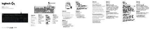
ENGLISH Knowyour product1. Game mode key2. Backlight brightness3. Mute4. USB cable connector5. Volume6. Media keys 繁体中文瞭解您的產品1. 遊戲模式按鍵2. 背光亮度3. 靜音4. USB 連接線接頭5. 音量6. 媒體鍵한국어제품설명1. 게임 모드 키2. 백라이트 밝기3. 음소거4. USB 케이블커넥터5. 볼륨6. 미디어키简体中文了解您的产品1. 游戏模式按键2. 背光亮度3. 静音4. USB 线连接器5. 音量6. 媒体键G610 Orion Brown™Backlit Mechanical Gaming KeyboardENGLISHSet up your product1. Turn on your computer.2. Connect the keyboard to USB port.3. Download and installthe Logitech® Gaming Softwarefrom /support/g610-brown.繁体中文設定您的產品1. 開啟電腦電源。
2. 將鍵盤連接到 USB 連接埠。
3. 在 /support/g610-brown.下載羅技®遊戲軟體並進行安裝。
한국어제품설정1. 컴퓨터를켭니다.2. USB 포트에키보드를연결합니다.3. /support/g610-brown에서 Logitech®게임소프트웨어를다운로드하여설치하십시오.简体中文设置您的产品1. 打开计算机。
2. 将键盘连接到 USB 端口。
3. 从 / support/g610-brown下载并安装罗技®游戏软件。
Setup Guide · 設定指南 · 설치 설명서 · 设置指南ENGLISHProduct featuresGame/Windows keyBy default, this key disables the standardWindows key and Menu key to preventthe Windows Start menu fromactivating during a game, whichmight disrupt play. This key can beprogrammed to block additional keysusing Logitech® Gaming Software.The game mode LED is lit during gamemode.Keyboard backlightingControl brightness with backlightbrightness key. Control individualkey brightness using LogitechGaming Software.Download and install the LogitechGaming Software from/support/g610-brown.繁体中文產品功能遊戲/Windows 鍵在預設情況下,此按鍵可停用標準Windows 鍵與功能表鍵,以防止在遊戲中不慎啟動 Windows「開始」功能表而中斷遊戲。
WORLDE PANDAMINIc MIDI 键盘使用说明书

WORLDE PANDAMINIc MIDI键盘使用说明书目录●简介 (3)●产品特性 (3)●各组成部分及其功能详解 (5)●设置 (7)■操作系统要求 (7)●具体设置 (8)■全局MIDI 通道 (8)■键盘控制器模式通道 (8)■移调 (9)■音高速度 (9)■按键力度曲线 (9)■打击垫力度曲线 (9)■打击垫 (10)■旋钮 (12)■推杆 (14)■编辑模式下的键盘操作 (16)●技术规格 (18)●简介感谢您使用WORLDE PANDAMINIc USB MIDI 控制器。
为了能完全了解这个新产品,请您仔细阅读这本说明书。
为了使用这个产品的功能,您将需要在您所使用的设备上对此产品进行设置。
请根据此说明书中描述的关于具体设置的内容来进行设置。
●产品特性●8个带力度感应的打击垫(带RGB彩色背光灯)可用于分配控制器,带3种力度曲线及一种持续(固定)力度。
●25个带力度感应的可分配的琴键,带3种力度曲线及一种持续(固定)力度。
●4个可分配控制旋钮。
●4个可分配控制推杆。
●4个用于不同设置的库。
●USB接口,适用于USB2.0(全速)。
●USB供电。
●兼容Win10/8/7/XP/Vista及Mac OSX。
●无需驱动,支持热插拔。
●提供软件编辑器,软件编辑器操作界面如下图所示。
●各组成部分及其功能详解1.打击垫打击垫用于传输音符信息或控制器信息。
打击垫带RGB 彩色背光灯,使用软件编辑器可编辑打击垫的RGB 背光灯颜色。
2.键盘25个带力度感应的琴键能传输音符信号。
在控制器模式下,各琴键能传输控制器信号。
3. MIDI 控制组⑥①②③④⑤⑦⑧1个旋钮、推杆、按钮的组合称为一个MIDI控制组。
PANDAMINIc有4个MIDI控制组。
a.旋钮旋钮用于传输控制器信息。
b.推杆推杆用于传输控制器信息。
4. [八度向下]/[八度向上]按钮这些按钮能调节键盘的音高。
每按一下[◄]按钮音高将低一个八度。
- 1、下载文档前请自行甄别文档内容的完整性,平台不提供额外的编辑、内容补充、找答案等附加服务。
- 2、"仅部分预览"的文档,不可在线预览部分如存在完整性等问题,可反馈申请退款(可完整预览的文档不适用该条件!)。
- 3、如文档侵犯您的权益,请联系客服反馈,我们会尽快为您处理(人工客服工作时间:9:00-18:30)。
设置键盘地址 1~8 为键盘可编地址,键盘缺省地址是 8。
如果要改变键盘地址,请依照如下步骤: 1. 进入键盘编址模式:给键盘上电,在上电后 60 秒内,同时
按住 STAY(留守)键及 CODE(编码)键约 3 秒钟。(如果 不能进入键盘编址模式,请上电重试。) 当前的键盘的地址将会显示出来,如果在 10 秒钟内没有按 键,键盘将自动退出地址模式。
至于本报警设备的一些授权信息和系统局限性,请参考随机配送的产品安装手册。
ÊK3590-FBIIhŠ
K3590-FBII 6/00
165 Eileen Way Syosset, NY 11791 Copyright © 2000 PITTWAY CORPORATION
Omni-LCD:
电流: Omni-KP:
Omni-LCD:
固定字符 LCD (背光) 2 x 16 个可变字符的 LCD 显示( 背光)
压电式 (火警音量高,脉冲单音(所有键盘均适用) , 盗警高音量,持续双音。 扬声器.
报警状态下 70mA, 待机模式下 40mA. 报警状态下 150mA 待机模式下 40mA
DI:数据输入到控制主机;━:地线, +:电源正极输入,
DO:主机的数据输出。.
5. 重新装好后盖。.
ARMED READY
Y
1
BYPASS
4
INSTANT
7
CODE
2
3
5
6
8
9
0
#
Omni-KP 键盘
ARMED READY
STAY
1
2
3
BYPASS
4
5
6
INSTANT
7
8
9
CODE
0
#
Omni-LCD 键盘
Omni-LCD: 在蜂鸣器菜单中有四种模式可以选择,分列如下:
• Off – 不发声 • Key –按键才发声 • Fire – 火警时才发声(临时警号,但不一定所有的主机
都有该功能)。 • On –打开扬声器(即系统设定该发声时均有声音提示)
显示: Omni-KP: Omni-LCD: 蜂鸣器: Omni-KP:
为了方便使用,键盘按键的背光灯是常亮的。
键盘显示及 LED 指示灯
键盘有下列显示功能:
模式
固定字符 2 行可变字
显示
符显示
Omni-KP
X
Omni-LCD
X
2 位防区标识 符
X
定制防区描述 符
X
下表是 LED 灯的类型及其功能:
LED
功能
红
当系统在任何模式下有报警时亮。
绿
当系统在“准备好”状态下亮。
规格 尺寸: Omni-KP: Omni-LCD:
5"高 x 6-1/2"宽 x 1-5/16"厚 5-5/16"高 x 7-1/2"宽 x 1-5/16"厚
连线 (所有键盘):
端子
连线
DO
绿
+
红
—
黑
DI
黄
打开/关闭蜂鸣器
Omni-KP: 同时按住 旁路 键及 编码 键约 2 秒钟,直到听到“哔”的 一声响。如果键盘蜂鸣器当前状态是关闭的,该动作将打 开蜂鸣器;如果蜂鸣器当前状态是打开的,该动作将关闭 蜂鸣器。
要使用蜂鸣器菜单,请参考以下步骤: 1. 同时按住 BYPASS 键及 CODE 键,持续 2 秒钟,将进入蜂 鸣器菜单。 2. 按下[1]键可在上面所示的模式中切换(在看到您需要的模 式时停止切换)。 3. 按下[2]键可在蜂鸣器的音量选项中切换(键盘上显示为高 或低)。 4. 按下[3 键调校按键的声音(键盘上显示 H 或 L)。 5. 按下[*] 键退出蜂鸣器菜单。
K3590-FBII 6/00
控制键盘 Omni-KP & Omni-LCD
安装指导
键盘功能
背光显示 内置蜂鸣器
Omni-KP 固定字符
有(查看注释 1) 压电蜂鸣器
Omni-LCD 2 行可变字符 有(查看注释 1)
扬声器
注释: 在一些控制主机可选背光灯是否常亮(详情请查看主机安装手册)。
Omni-KP 和 Omni-LCD 键盘都是可编址键盘,适用于 FBII OMNI 系列的控制主机。键盘地址可通过键盘进行设置。
连线及安装 该类键盘可直接安装在干燥的墙面上,或是安装在电气箱面板 上。 1. 用一把合适的螺丝刀,打开键盘后盖。往下压键盘底部的两
个锁扣即可打开键盘后盖。
2. 从控制主机接线至键盘。通过后盖上的进线孔走线,预留适 当长度。
3. 将后盖安装在干燥的墙面上,或箱子面板上。
4. 从控制主机连线至键盘的接线端子。各根线的功能都标示在 相应端子的下面,标签如下所示:
如果您想接着再进入键盘编址模式,只能对主机重新上 电,再进入该模式。 2. 如果主机不能发送一个有效的命令给键盘,键盘上将显示空 屏。 3. 退出键盘编址模式: 按[*]可保存显示的地址并退出编址模式。
查看键盘地址 同时按住 STAY(留守)键及 CODE(编码)键约 3 秒钟,当前 地址将会显示出来,但不允许输入字符。可按任意键退出或等 候 10 秒钟,系统会自动退出该显示模式。