T436432B中文资料
废钢国家标准

由国家质量监督检验检疫总局、国家标准化管理委员会发布的新修改的《废钢铁》国家标准(GB4223-2004)经批准发布,于2004年12月1日起正式实行。
ICS 77.080.0H 41中华人民共和国国家标准GB 4223-2004代替GB/T 4223-1996废钢铁Iron and steel scraps2004-05-20 发布2004-12-01 实施中华人民共和国国家质量监督检验检疫总局中国国家标准化管理委员会发布GB 4223-2004前言本标准的第5章为强制性的,其余为推荐性的。
本标准与JISG 2401-1979《废钢分类》一致性程度为非等效。
本标准代替GB/T 4223-1996《废钢铁》。
本标准与GB/T 4223-1996相比技术内容进行了如下修改:----取消了再生用废钢的定义及相关内容;规定了废钢铁单件的最大尺寸和最大重量;----取消了原标准中的4条术语,增加了6条术语及其定义;----改变了废铁的分类,以废铁的化学成分、外形尺寸为划分依据,将废铁分为3类、4个品种;----改变了废钢的分类,提出了新的外形尺寸和单重以及相应的验收条件,并将废钢分为重型废钢、中型废钢、小型废钢、统料型废钢、轻料型废钢5类;----调整合金废钢的分组,由原标准的5个钢类67个钢组,合并、简化成6个钢类46个钢组,并将其调整为资料性附录;----降低了废钢中S、P的含量,由原标准的0.080%,改为0.050%;----增加了对废钢铁必须分类的要求;----增加了对环保控制、放射性物质控制等方面的要求,增加了检验项目和试验方法的部分内容。
本标准自实施之日起,废止GB/T 4223-1996《废钢铁》。
本标准的附录A为规范性附录,附录B为资料性附录。
本标准由中国钢铁工业协会提出。
本标准由冶金工业信息标准研究院归口。
本标准起草单位:马鞍山钢铁股份有限公司、冶金工业信息标准研究院、川投长城特殊钢股份有限公司、鞍山钢铁公司、本溪钢铁公司。
3843B资料
TL3843BD-8
SOIC – D (8 pin)
Reel of 2500 Tube of 75
TL3843BDTL3844BDR-8
Tube of 75
TL3845BD-8
Reel of 2500
TL3845BDR-8
Tube of 75
TL3842BD
Copyright © 2006, Texas Instruments Incorporated
元器件交易网
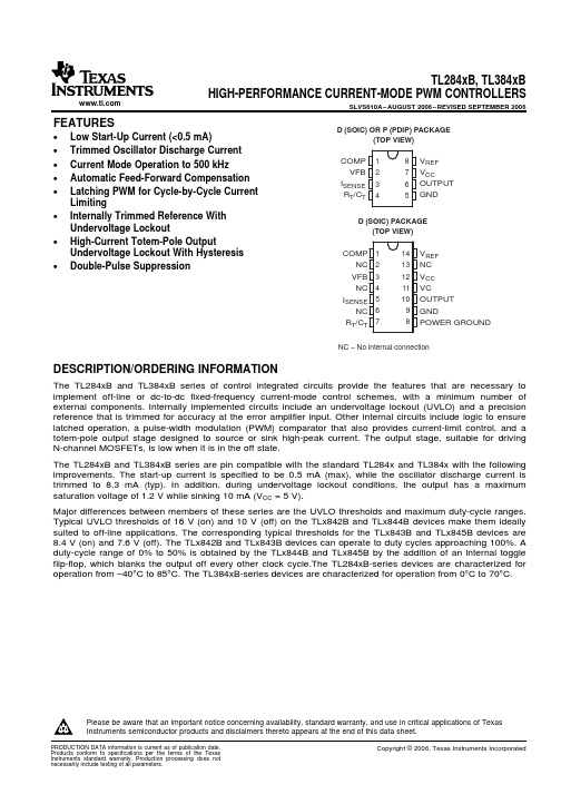
TL284xB, TL384xB HIGH-PERFORMANCE CURRENT-MODE PWM CONTROLLERS
SLVS610A – AUGUST 2006 – REVISED SEPTEMBER 2006
S
R
CurrentSense
Comparator
PWM Latch
Submit Documentation Feedback
3
元器件交易网
TL284xB, TL384xB HIGH-PERFORMANCE CURRENT-MODE PWM CONTROLLERS
Reel of 2500
TL3842BDR
Tube of 75
TL3843BD
SOIC – D (14 pin)
Reel of 2500 Tube of 75
TL3843BDR TL3844BD
Reel of 2500
TL3844BDR
Tube of 75
TL3845BD
Reel of 2500
TL3845BDR
RT/CT 7
14 VREF 13 NC 12 VCC 11 VC 10 OUTPUT 9 GND 8 POWER GROUND
TQB4CM184产品安装手册说明书

Please return this guide to the customer after installation for future reference.
Drill Guide User's Manual Bracket A x2 Bracket B x2 Wall Anchor x8
Screw a x8 Screw b x4 (M4x15mm) Label sticker x2 (50x55mm)
Store the removed parts in a safe place for later use.
Do not modify any accessory, design, or structure. (Doing so may cause the display to fall and cause damage to the display and injury)
Please check carefully before installation the area where the wall mount will be installed. -Avoid any outdoor or similar place. -Avoid any place with high temperature or
Images in this guide are for reference only and may be different from the actual product.
潍杰2008年自动变速箱配件及组件目录说明书
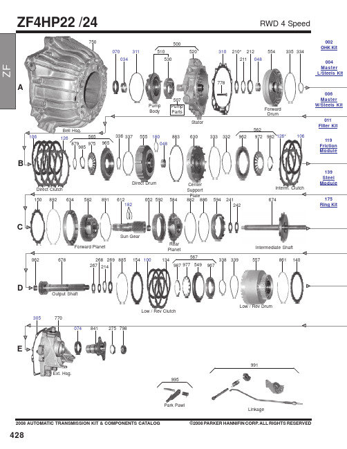
2008 AUTOMATIC TRANSMISSION KIT & COMPONENTS CATALOG©2008 PARKER HANNIFIN CORP. ALL RIGHTS RESERVEDEA750Direct DrumInterm. ClutchForward PlanetSun GearRearOutput ShaftLow / Rev ClutchLow / Rev DrumExt. Hsg.Linkage991Park Pawl995778CenterPumpParts507139SteelModule4282008 AUTOMATIC TRANSMISSION KIT & COMPONENTS CATALOG ©2008 PARKER HANNIFIN CORP . ALL RIGHTS RESERVEDBCE 642144106126989979969340341639632Overrun Clutch569339338966976893126104566062620062213779300765010V.B.Parts741748O.Dr. PlanetInput ShaftGov.048740Valve Body431421421386429006.............B69006..........Master W/Steels Kit, ZF3HP22 1976-84.....................................................................................1..........006.............T69006A........Master W/Steels Kit, ZF4HP22 1984-Up....................................................................................1..........006.............B69006A.......Master W/Steels Kit, ZF4HP22 1984-96 BMW, Audi..................................................................1..........006.............B69006B........Master W/Steels Kit, ZF4HP22 1984-96 With 5 Extra................................................................1..........006.............T69006E........Master W/Steels Kit, ZF4HP24 1988-96.....................................................................................1..........006.............B69006E........Master W/Steels Kit, ZF4HP24 1988-Up BMW, 750I..................................................................1..........E300...........31209............Gasket, ZF3HP22 Oil Pan 1984-On (Molded Rubber)...............................................................1..........24-11-1-205-903 E300...........31809............Gasket, ZF4HP22/24 Oil Pan (Molded Rubber)..........................................................................1..........24-11-1-215-488 E305...........31897589......Gasket, ZF4HP22 Extension Housing 1984-Up.........................................................................1. (070112012)A310..........31204............Gasket, ZF3HP22 Pump Stator To Bell Housing.........................................................................1. (1043322129)A310..........31897588......Gasket, ZF3HP22 Pump Plate To Stator.....................................................................................1. (750112009)A311...........1994785........O-Ring, ZF4HP22 Pump Body....................................................................................................1. (734313061)...................31897592......Gasket, ZF4HP22 Valve Body (Upper) 1984-On.......................................................................1. (1043326253)...................31897593......Gasket, ZF4HP24 Valve Body (Lower) Electronic 1984-On.....................................................1. (1043328080)A070..........70247............Seal, ZF3HP22/ZF4HP22/ZF4HP24/ZF4HP14 Front 1976-Up...................................................1..........24-311-207-621 D072...........70249............Seal, ZF3HP22/ZF4HP22/ZF4HP24 Manual Lever Seal 1976-Up.............................................1. (750110062)E074...........70248............Seal, ZF3HP22/ZF4HP22/ZF4HP24/ZF4HP14/4L30E Extension Housing (2 1/2"OD) BMW,...........................................Peugeot 1984-On.......................................................................................................................1..........046-504-4002H E074...........70028............Seal, ZF4HP22/C-3/A4LD/4R44E/4R55E/5R55E Extension Housing (Lincoln With Boot).........1..........E2ZZ-7052-A175.............31260............Ring Kit, ZF3HP22 1976-86 (5 Pieces)......................................................................................1..........175.............6182..............Ring Kit, ZF4HP22 1984-Up........................................................................................................1..........175.............6182OS.........Ring Kit, ZF4HP22 1984-Up........................................................................................................1..........A177..........30819............Ring, ZF4HP22 Input Shaft (PTFE) 1984-Up..............................................................................1..........B180...........TAW-2165.....Ring, ZF3HP22/ZF4HP22 Direct Clutch Drum (Metal)................................................................1. (301302051)C182...........TAW-2168.....Ring, ZF3HP22/ZF4HP22 Sun Gear Shaft (Metal).....................................................................2. (750113021)D189...........31859V..........Ring, ZF4HP22 Governor (Viton)..............................................................................................1-3.. (501306311)...................31803-5.........Ring Kit, ZF4HP22 Governor (Viton) Contains 3 Rings.............................................................1. (501306311)D100...........31820R..........Friction, ZF4HP22 Low/Reverse & Overdrive Clutch (.061") 40 Teeth (E/F Pack) 1984-On...8..........24-23-1-214-441 D104...........31224R..........Friction, ZF3HP22/ZF4HP22 Reverse Clutch (.063") 48 Teeth (D Pack)..................................4-5........24-23-1-205-955 D104...........31824W.........Friction, ZF4HP22 Reverse Clutch (.061") 58 Teeth (D Pack) 1987-On...................................5..........1043-217-015 B106...........31222R..........Friction, ZF3HP22/ZF4HP22 Direct, Intermediate, & Overrun Clutch (.059") 1976-On............6-8........24-23-1-215-770 A108..........31822............Friction, ZF4HP24 Forward Clutch (.061") 40 Teeth (5"OD) (A Pack) 1988-Up......................4-6........1043-202-189 119.............31880............Fricton Module, ZF4HP22 1984-96............................................................................................1..........119.............31880R..........Friction Module, ZF4HP22 1984-96............................................................................................1..........119.............31882R..........Friction Module, ZF4HP24 1988-96............................................................................................1..........2008 AUTOMATIC TRANSMISSION KIT & COMPONENTS CATALOG©2008 PARKER HANNIFIN CORP. ALL RIGHTS RESERVED 4304312008 AUTOMATIC TRANSMISSION KIT & COMPONENTS CATALOG©2008 PARKER HANNIFIN CORP. ALL RIGHTS RESERVEDE010...........31240............Filter, ZF3HP22 1976-84.............................................................................................................1..........24-34-1-209-791E010...........31840............Filter, ZF4HP22 (No Pick-Up Tube) 1984-Up..............................................................................1..........24-31-1-218-550E010...........31841............Filter, ZF4HP22 (With 1” Long Pick-Up Tube) 1988-Up With Suction ........................................1..........24-31-1-218-204E010...........31843............Filter, ZF4HP24 Land Rover 1988-Up ........................................................................................1..........1043-226-037011.............31242............Filter Kit, ZF3HP22 1977-On.......................................................................................................1..........011.............31842............Filter Kit, ZF4HP22 (No Pick-Up Tube) 1984-On BMW ..............................................................1..........011.............31844............Filter Kit, ZF4HP22 (With 1 Pick-Up Tube) 1988-On ..................................................................1. (011).............31845............Filter Kit, ZF4HP24 Land Rover 1991-On...................................................................................1..........A034..........31230............Bushing, ZF3HP22/ZF4HP22 NPump 1976-93...........................................................................1..........750101031A034..........31232............Bushing, ZF4HP22/ZF4HP24 Pump 1994-Up.............................................................................1..........0501-311-812A/B048.......31231............Bushing, ZF4HP22/ZF4HP24 Forward Drum, Overdrive Drum, & Center Support Plate...........................................1976-Up .....................................................................................................................................1-3........E421...........S-159.............Solenoid, ZF4HP22/ZF4HP22 (Shift/TCC/Reverse Lock-Out)..................................................1-3........501307869E431...........S-157.............Solenoid, ZF4HP22/ZF4HP24 (EPC) Pressure Regulator Solenoid (Fits The 5 Solenoid...........................................Valve Body)................................................................................................................................1..........0501206997C650...........31885............Sprag, ZF4HP22 Overdrive Roller Clutch 3RD Design ..............................................................1..........C650...........31886............Sprag, ZF4HP22 Overdrive Roller Clutch 1ST Design...............................................................1..........。
德国工业实际联系部件编号说明说明书

0460-256-12**
12 PIN
1.5 mm² 16 AWG 1.0 mm²
18 AWG 0.75 mm²
35 [156] 25 [111]
.222-.284 [5.64-7.21]
0460-215-16** 0462-209-16**
16 PIN 16 SOC
14 AWG 2.0 mm²
70 [311]
7 CYCLE TOOL TO OPEN HANDLES. REMOVE LOCK CLIP. RAISE AND ROTATE DIAL TO SELECT WIRE SIZE. REPLACE LOCK CLIP.
6 WHEN **= 31, PLATING IS GOLD. WHEN **=141, PLATING IS NICKEL.
3 USE 1.5 SETTING FOR THIS PART WITH 14 AWG.
2 CAUTION: NEVER CLOSE TOOL ON GAGE G454. CLOSE TOOL FIRST AND THEN INSERT GAGE.
1 USE GAGE G454 IN DCHECK WEAR ANNUALLY. CHECK
1.5 mm² 16 AWG 1.0 mm²
18 AWG 0.75 mm²
4.0 mm² 12 AWG 3.0 mm² 2.5 mm²
35 [156] 25 [111]
.222-.284 [5.64-7.21]
75 [334]
.222-.284 [5.64-7.21]
SLOTTED (SPLIT) PIN 11
NOTES: UNLESS OTHERWISE SPECIFIED
洗衣机干衣机熔断器技术规范

德信诚培训网熔断器通用技术规范1.范围本标准规定了用熔断器的产品分类、技术要求、试验方法、检验规则、标志、包装、运输和贮存。
本标准适用于各种型号家用洗衣机和干衣机熔断器。
2.引标准下列标准所包含的条文,通过在本标准中引用而构成为本标准的条文。
本标准出版时,所示版本均为有效。
所有标准都会被修订,使用本标准的各方应探讨使用下列标准最新版本的可能性。
GB/T5095.8电子设备用机电元件基本试验规程及测量方法第8部分:连接器、接触件及引出端的机械试验GB5023.2 额定电压450/750V及以下聚氯乙烯绝缘电缆试验方法GB5023.5 额定电压450/750V及以下聚氯乙烯绝缘电缆软电缆(软线)GB9364.1 小型熔断器第1部分:小型熔断器定义和小型熔断体通用要求GB9364.2 小型熔断器第2部分:管状熔断体GB9364.3 小型熔断器第3部分:超小型熔断体GB9364.6 小型熔断器第6部分小型管状熔断体的熔断器座GB 4706.1 家用类似用途电器的安全通用要求德信诚培训网3 技术参数额定电压 100VAC-250V额定电流参照图纸的要求额定频率 45Hz~62Hz导线规格参照图纸的要求4 技术要求4.1外观要求熔断器外壳表面应光滑、无气孔、裂纹、凹凸、破损、花斑、污浊等。
4.2结构尺寸4.2.1熔断器应按规定程序批准的图纸和技术文件制造。
4.2.2熔断器的长度、剥线长度、导线截面尺寸应符合图纸及本标准要求。
4.2.3熔断器上导线的绝缘应是PVC/D型聚氯乙烯混合物,绝缘厚度应符合相关的国家标准的规定值。
4.3.阻燃性能按照5.4条方法进行试验,熔断器的外壳应符合阻燃性能要求.4.4接触电阻按照5.5条方法进行试验,熔断器的接触电阻≤100mΩ4.5导线的拉脱力按照5.6条方法进行试验,导线承受30N拉力不被拉出或断裂4.6电气强度。
436A电力表操作与服务手册说明书
ErrataTitle & Document Type: 436A Power Meter Operating and Sevice Manual Manual Part Number: 00436-90053Revision Date: 1988-03-01HP References in this ManualThis manual may contain references to HP or Hewlett-Packard. Please note that Hewlett-Packard's former test and measurement, semiconductor products an d chemical analysis businesses are now part of Agilent Technologies. We have made no changes to this manual copy. The HP XXXX referred to in this document is now the Agilent XXXX. For example, model number HP8648A is now model number Agilent 8648A.About this ManualWe’ve added this manual to the Agilent website in an effort to help you support your product. This manual provides the best information we could find. It may be incomplete or contain dated information, and the scan quality may not be ideal. If we find a better copy in the future, we will add it to the Agilent website.Support for Your ProductAgilent no longer sells or supports this product. You will find any other available product information on the Agilent Test & Measurement website:Search for the model number of this product, and the resulting product page will guide you to any available information. Our service centers may be able to perform calibration if no repair parts are needed, but no other support from Agilent is available.。
SL432B中文资料

SL432x S e m i c o n d u c t o rProgrammable Voltage ReferenceSL432xAbsolute maximum ratings [Ta=25℃]Characteristic Symbol Rating Unit Cathode to Anode voltage V KA 18 V=mA Cathode current I K 30Reference input current I ref 3mA Power Dissipation P D 625mW Junction Temperature T J 150℃Operating temperature range T opr-40 ~ +85 ℃Storage temperature range T stg-55 ~ +150 ℃Recommended operating conditionsRatingUnitCharacteristic SymbolMin. Max.Cathode to Anode voltage V KA V ref 16 VCathode current I K 0.1mA25SL432x1ref 21ref KA R ×I +)R R +1(×V =V Note.T ∆)10×)℃25=T (V (=)℃ppm (V αaa ref refref ref V αcan be positive or negative depending on whether V ref Min or V ref Max occurs at the lower ambient temperature, refer toFig. 8Example : △V ref = 10mV and the slope is positive,△V ref @ 25℃ = 1.24V △T a = 125℃℃/ppm 65=12510×)241.1010.0(=℃ppm (V α6ref3. The dynamic impedance Z KA is defined as:KKAKA I ∆V ∆=Ζ When the device is operating with two external resistors, R1 and R2, (refer to Fig.2) the total dynamic impedance of the circuit is given by:R R +1(×Ζ=Ζ21KA 'KA Fig. 1 Test circuit for V KA =V ref Fig. 2 Test circuit for V KA >V refFig. 3 Test circuit for I K(off)ref Min V refElectrical Characteristics Curves (Continue)Cathode V oltage V KA [V]0.0200.10.30.2016 8 0.4O f f -s t a t e c a t h o d e c u r r e n t I K (o f f ) [µA ]12 4 Fig.4 I K vs V KA (1)Fig.5 I K vs V KA (2)I 10-10C a t h o d e c u r r e n t I K [m A ]30Fig.8 V ref vs T aR e f e r e n c e i n p u t v o l t a g e V r e f [V ]50 0 -257525 100-50R Ambient Temperature T a [˚C]Fig.9 P D vs T aAmbient Temperature T a [˚C]10050 2512575 1500 P o w e r d i s s i p a t i o n P D [m W ]1000600800200400Electrical Characteristics CurvesUnstable RegionsV KA R 1 [K Ω] R 2 [K Ω]A, BV ref 0 ∞A 10V 10 1.415The AUK Corp. products are intended for the use as components in general electronic equipment (Office and communication equipment, measuring equipment, home appliance, etc.).Please make sure that you consult with us before you use these AUK Corp. products in equipments which require high quality and / or reliability, and in equipments which could have major impact to the welfare of human life(atomic energy control, airplane, spaceship, transportation, combustion control, all types of safety device, etc.). AUK Corp. cannot accept liability to any damage which may occur in case these AUK Corp. products were used in the mentioned equipments without prior consultation with AUK Corp..Specifications mentioned in this publication are subject to change without notice.Fig.10 Stability Boundary ConditionsFig.11 Test circuit for Fig. 10。
- 1、下载文档前请自行甄别文档内容的完整性,平台不提供额外的编辑、内容补充、找答案等附加服务。
- 2、"仅部分预览"的文档,不可在线预览部分如存在完整性等问题,可反馈申请退款(可完整预览的文档不适用该条件!)。
- 3、如文档侵犯您的权益,请联系客服反馈,我们会尽快为您处理(人工客服工作时间:9:00-18:30)。
SDRAM 2M x 32 SDRAM512K x 32bit x 4Banks Synchronous DRAMFEATURES• 3.3V power supply•Clock cycle time : 5 / 5.5 / 6 / 7 / 8 / 10 ns • Internal four banks operation•LVTTL compatible with multiplexed address •All inputs are sampled at the positive going edge of system clock•Burst Read Single-bit Write operation •DQM for masking•Auto refresh and self refresh• 64ms refresh period (4K cycle)• MRS cycle with address key programs- CAS Latency ( 2 & 3 )- Burst Length :1 ,2 , 4 , 8 or full page for Sequential Burst 1 , 2 , 4 or 8 for Interleave Burst• Available package type :- 86 pin 400mil TSOP(II) and Lead free• Operating temperature :- 0 ~ +70 °CPART NUMBER EXAMPLES GRNERAL DESCRIPTIONThe T436432B is 67,108,864 bits synchronoushigh data rate Dynamic RAM organized as 4 x 524,288 words by 32 bits , fabricated with high performance CMOS technology . Synchronous design allows precise cycle control with the use of system clock I/O transactions are possible on every clock cycle . Range of operating frequencies , programmable burst length and programmable latencies allow the same device to be useful for a variety of high bandwidth , high performance memory system applications.PART NO.CLOCKCYCLE TIMEMAXFREQUENCYPACKAGEOPERATINGTEMPERATURET436432B-5SG 5ns 200 MHz TSOP-II Lead free 0 ~ +70 °C T436432B-5S 5ns 200 MHz TSOP-II 0 ~ +70 °C T436432B-55SG 5.5ns 183 MHz TSOP-II Lead free 0 ~ +70 °C T436432B-55S 5.5ns 183 MHz TSOP-II 0 ~ +70 °C T436432B-6SG 6ns 166 MHz TSOP-II Lead free 0 ~ +70 °C T436432B-6S 6ns 166 MHz TSOP-II 0 ~ +70 °C T436432B-7SG 7ns 143 MHz TSOP-II Lead free 0 ~ +70 °C T436432B-7S 7ns 143 MHz TSOP-II 0 ~ +70 °C T436432B-8SG 8ns 125 MHz TSOP-II Lead free 0 ~ +70 °C T436432B-8S 8ns 125 MHz TSOP-II 0 ~ +70 °C T436432B-10SG 10ns 100 MHz TSOP-II Lead free 0 ~ +70 °C T436432B-10S 10ns 100 MHz TSOP-II 0 ~ +70 °CPIN ARRANGEMENT(TSOP-II Top View)VD D QVD DVD D QD Q 11D Q 10A 8A 7A 9D Q 1D Q 2N .C B S 0D Q 15D Q 14VS S QV s s VS S QD Q 0D Q 3D Q 4VD D QD Q 5D Q 6R A S C S B S 1A 10/A PA 0VS S QD Q 13D Q 12D Q 9N .C D Q M 1N .C A 6A 5A 4VS S QD Q 7N .C D Q 8N .C W E C A S D Q M 2A 1VS S QN .C D Q 16A 2VS S QD Q 17D Q 18VD D QD Q 19D Q 20VS S QD Q 21VD D QD Q 30D Q 29A 3D Q M 3VS S QV s s VS SN .C D Q 31D Q 28D Q 25C K E D Q 24D Q 27VD D QD Q 26VD DD Q M 0VD DD Q 22VD D QD Q 23VD DV s sVD D QC L KBLOCK DIAGRAMDQDQMRAS CS CKE CLK ADDCAS W EOperation ModeFully synchronous operations are performed to latch the commands at the positive edges of CLK. Table 2 shows the truth table for the operation commands.Table 2. Truth Table (Note (1), (2) )Command State CKE n-1 CKE n DQM (6) BS 0,1 A 10A 9-0 CS# RAS# CAS# WE#BankActivate Idle (3) H X X V Row address L L H H BankPrecharge Any H X X V L X L L H L PrechargeAll Any H X X X H X L L H LWriteActive (3) H X X V LL H L L Write and AutoPrecharge Active (3) H X X V H Column address (A0~ A7) L H L L ReadActive (3) H X X V LL H L H Read and Autoprecharge Active (3) H X X V H Column address (A0~ A7) L H L H Mode Register Set Idle H X X OP codeL L L LNo-Operation AnyH X X X X X L H H HBurst Stop Active (4) H X X X X X L H H L Device Deselect Any H X X X X X H X X X AutoRefresh Idle H H X X X X L L L H SelfRefresh Entry Idle H L X X X X L L L H SelfRefresh Exit Idle L H X X X X H X X X(SelfRefresh) L H H H Clock Suspend Mode Entry Active H L X X X X X X X X Power Down Mode Entry Any (5) H L X X X X H X X XL H H HClock Suspend Mode Exit Active L H X X X X X X X X Power Down Mode Exit Any L H X X X X H X X X(PowerDown) L H H H Data Write/Output Enable Active H X L X X X X X X XData Mask/Output DisableActive H X H X X X X X X XNote: 1. V = Valid, X = Don't care, L = Logic low, H = Logic high2. CKE n signal is input level when commands are provided.CKE n-1 signal is input level one clock cycle before the commands are provided. 3. These are states of bank designated by BS signal.4. Device state is 1, 2, 4, 8, and full page burst operation.5. Power Down Mode can not enter in the burst operation.When this command is asserted in the burst cycle, device state is clock suspend mode. 6. DQM0-3Commands1 BankActivate (RAS# = "L", CAS# = "H", WE# = "H", BS = Bank, A0-A10 = Row Address) The BankActivate command activates the idle bank designated by the BS0,1 (Bank Select) signal. Bylatching the row address on A0 to A10 at the time of this command, the selected row access is initiated. The read or write operation in the same bank can occur after a time delay of t RCD (min.) from the time of bank activation. A subsequent BankActivate command to a different row in the same bank can only be issued after the previous active row has been precharged (refer to the following figure). The minimum time interval between successive BankActivate commands to the same bank is defined by t RC (min.). The SDRAM has four internal banks on the same chip and shares part of the internal circuitry to reduce chip area; therefore it restricts the back-to-back activation of the four banks. t RRD (min.) specifies the minimum time required between activating different banks. After this command is used, the Write command and the Block Write command perform the no mask write operation.CLK ADDRESST0T 1T2T3Tn+3Tn+4T n+5Tn+6COMMANDBeginBankActivate Command Cycle (Burst Length = n, CAS# Latency = 3)2 BankPrecharge command (RAS# = "L", CAS# = "H", WE# = "L", BS = Bank, A10 = "L", A0-A9 = Don't care) The BankPrecharge command precharges the bank disignated by BS0,1 signal. The precharged bank isswitched from the active state to the idle state. This command can be asserted anytime after t RAS (min.) is satisfied from the BankActivate command in the desired bank. The maximum time any bank can be active is specified by t RAS (max.). Therefore, the precharge function must be performed in any active bank within t RAS (max.). At the end of precharge, the precharged bank is still in the idle state and is ready to be activated again. 3 PrechargeAll command (RAS# = "L", CAS# = "H", WE# = "L", BS = Don’t care, A10 = "H", A0-A9 = Don't care) The PrechargeAll command precharges all the four banks simultaneously and can be issued even if allbanks are not in the active state. All banks are then switched to the idle state. 4 Read command (RAS# = "H", CAS# = "L", WE# = "H", BS = Bank, A10 = "L", A0-A7 = Column Address) The Read command is used to read a burst of data on consecutive clock cycles from an active row in anactive bank. The bank must be active for at least t RCD (min.) before the Read command is issued. During read bursts, the valid data-out element from the starting column address will be available following the CAS# latency after the issue of the Read command. Each subsequent data-out element will be valid by the next positive clock edge (refer to the following figure). The DQs go into high-impedance at the end of the burst unless other command is initiated. The burst length, burst sequence, and CAS# latency are determined by the mode register which is already programmed. A full-page burst will continue until terminated (at the end of the page it will wrap to column 0 and continue).CLK COMMAND CAS# latency=2t CK2, DQ's CAS# latency=3t CK3, DQ'sT0T1T2T3T4T5T6T7T8Burst Read Operation(Burst Length = 4, CAS# Latency = 2, 3)The read data appears on the DQs subject to the values on the DQM inputs two clocks earlier (i.e. DQM latency is two clocks for output buffers). A read burst without the auto precharge function may be interrupted by a subsequent Read or Write command to the same bank or the other active bank before the end of the burst length. It may be interrupted by a BankPrecharge/ PrechargeAll command to the same bank too. The interrupt coming from the Read command can occur on any clock cycle following a previous Read command (refer tothe following figure).CLK COMMANDCAS# latency=2t CK2, DQ's CAS# latency=3t CK3, DQ'sT0T 1T2T3T4T5T6T7T8Read Interrupted by a Read (Burst Length = 4, CAS# Latency = 2, 3)The DQM inputs are used to avoid I/O contention on the DQ pins when the interrupt comes from a Write command. The DQMs must be asserted (HIGH) at least two clocks prior to the Write command to suppress data-out on the DQ pins. To guarantee the DQ pins against I/O contention, a single cycle with high-impedance on the DQ pins must occur between the last read data and the Write command (refer to the following three figures). If the data output of the burst read occurs at the second clock of the burst write, the DQMs must be asserted (HIGH) at least one clock prior to the Write command to avoid internal bus contention.CLK DQM COMMANDDQ'sT0T1T2T3T4T 5T6T 7T8Read to Write Interval (Burst Length • 4, CAS# Latency = 3)CLK DQMCOMMANDT0T 1T2T3T4T5T6T7T8CAS# latency=2t CK2, DQ'sRead to Write Interval (Burst Length ≥ 4, CAS# Latency = 2)CLK DQMCOMMAND T0T1T2T3T4T5T6T7T8CAS# latency=2t , DQ'sRead to Write Interval (Burst Length ≥ 4, CAS# Latency = 2)A read burst without the auto precharge function may be interrupted by a BankPrecharge/ PrechargeAll command to the same bank. The following figure shows the optimum time that BankPrecharge/ PrechargeAll command is issued in different CAS# latency.CLK COMMANDCAS# latency=2t CK2, DQ'sCAS# latency=3t CK3, DQ'sADDRESS Read to Precharge (CAS# Latency = 2, 3)5 Read and AutoPrecharge command(RAS# = "H", CAS# = "L", WE# = "H", BS = Bank, A10 = "H", A0-A7 = Column Address)The Read and AutoPrecharge command automatically performs the precharge operation after the read operation. Once this command is given, any subsequent command cannot occur within a time delay of {t RP (min.) + burst length }. At full-page burst, only the read operation is performed in this command and the auto precharge function is ignored.6 Write command (RAS# = "H", CAS# = "L", WE# = "L", BS = Bank, A10 = "L", A0-A7 = Column Address) The Write command is used to write a burst of data on consecutive clock cycles from an active row in anactive bank. The bank must be active for at least t RCD (min.) before the Write command is issued. During write bursts, the first valid data-in element will be registered coincident with the Write command. Subsequent data elements will be registered on each successive positive clock edge (refer to the following figure). The DQs remain with high-impedance at the end of the burst unless another command is initiated. The burst length and burst sequence are determined by the mode register, which is already programmed. A full-page burst will continue until terminated (at the end of the page it will wrap to column 0 and continue).CLKCOMMAND DQ0 - DQ3are registered o n the same clock edge.Burst Write Operation (Burst Length = 4, CAS# Latency = 1, 2, 3)A write burst without the AutoPrecharge function may be interrupted by a subsequent Write, BankPrecharge/PrechargeAll, or Read command before the end of the burst length. An interrupt coming from Write command can occur on any clock cycle following the previous Write command (refer to the following figure).CLK COMMANDDQ'sWrite Interrupted by a Write (Burst Length = 4, CAS# Latency = 1, 2, 3)The Read command that interrupts a write burst without auto precharge function should be issued onecycle after the clock edge in which the last data-in element is registered. In order to avoid data contention, input data must be removed from the DQs at least one clock cycle before the first read data appears on the outputs (refer to the following figure). Once the Read command is registered, the data inputs will be ignored and writes will not be executed.CL K COM MA NDdata contention.CAS# latency=2t CK2, DQ's CAS# latency=3t CK3, DQ'sWrite Interrupted by a Read (Burst Length = 4, CAS# Latency = 2, 3)The BankPrecharge/PrechargeAll command that interrupts a write burst without the auto precharge function should be issued m cycles after the clock edge in which the last data-in element is registered, where m equals t WR /t CK rounded up to the next whole number. In addition, the DQM signals must be used to mask inputdata, starting with the clock edge following the last data-in element and ending with the clock edge on whichthe BankPrecharge/PrechargeAll command is entered (refer to the following figure).CLKT0T1T2T3T4T 5T6COMMANDDQMADDRESSDQNote:The DQMs can remain low in this example if the length of the write burst is 1 or 2. Write to Precharge7 Write and AutoPrecharge command (refer to the following figure)(RAS# = "H", CAS# = "L", WE# = "L", BS = Bank, A10 = "H", A0-A7 = Column Address)The Write and AutoPrecharge command performs the precharge operation automatically after the write operation. Once this command is given, any subsequent command can not occur within a time delay of {(burst length -1) + t WR + t RP(min.)}. At full-page burst, only the write operation is performed in this command and the auto precharge function is ignored.CLK COMMAND T0T1T2T3T4T5T6T7T8CAS# latency=2t CK2, DQ'sCAS# latency=3t CK3, DQ'st DAL= t WR + t RP*Beg in AutoPre chargeBank can be rea ctivated at com pletion of t DALBurst Write with Auto-Precharge (Burst Length = 2, CAS# Latency = 2, 3)8 Mode Register Set command(RAS# = "L", CAS# = "L", WE# = "L", BS0,1 and A10-A0 = Register Data)The mode register stores the data for controlling the various operating modes of SDRAM. The Mode Register Set command programs the values of CAS# latency, Addressing Mode and Burst Length in the Mode register to make SDRAM useful for a variety of different applications. The default values of the Mode Register after power-up are undefined; therefore this command must be issued at the power-up sequence. The state of pins BS0,1 and A10~A0 in the same cycle is the data written to the mode register. One clock cycle is required to complete the write in the mode register (refer to the following figure). The contents of the mode register can be changed using the same command and the clock cycle requirements during operation as long as all banks are in the idle state.RAS#T0T1T2T3T4T5T6T7T8T9T10CLKCKECS#CAS#WE#ADDR.DQMDQSet Command CommandMode Register Set Cycle (CAS# Latency = 2, 3)The mode register is divided into various fields depending on functionality.Address BS0,1 A10/AP A9 A8 A7 A6 A5 A4 A3 A2 A1 A0 Function RFU* RFU* WBL Test Mode CAS Latency BT Burst Length*Note: RFU (Reserved for future use) should stay “0” during MRS cycle.•Burst Length Field (A2~A0)This field specifies the data length of column access using the A2~A0 pins and selects the Burst Length to be 2, 4, 8, or full page.A2 A1 A0 BurstLength0 0 0 10 0 1 20 1 0 40 1 1 81 0 0 Reserved1 0 1 Reserved1 1 0 Reserved1 1 1 FullPage•Burst Type Field (A3)The Burst Type can be one of two modes, Interleave Mode or Sequential Mode.TypeA3 Burst0 Sequential1 Interleave--- Addressing Sequence of Sequential ModeAn internal column address is performed by increasing the address from the column address which is input to the device. The internal column address is varied by the Burst Length as shown in the following table. When the value of column address, (n + m), in the table is larger than 255, only the least significant 8 bits are effective.n 0 1 2 3 4 5 6 7 - 255 256 257 - DataColumn Address n n+1 n+2 n+3 n+4 n+5 n+6 n+7 - N+255 n n+1 -words:2Burst Length 4 words:words:8Full Page: Column address is repeated until terminated.--- Addressing Sequence of Interleave ModeA column access is started in the input column address and is performed by inverting the address bits in the sequence shown in the following table.Data n Column Address Burst Length Data 0 A7 A6 A5 A4 A3 A2 A1 A0Data 1 A7 A6 A5 A4 A3 A2 A1 A0# 4 wordsData 2 A7 A6 A5 A4 A3 A2 A1# A0Data 3 A7 A6 A5 A4 A3 A2 A1# A0# 8 words Data 4 A7 A6 A5 A4 A3 A2# A1 A0Data 5 A7 A6 A5 A4 A3 A2# A1 A0#Data 6 A7 A6 A5 A4 A3 A2# A1# A0Data 7 A7 A6 A5 A4 A3 A2# A1# A0#•CAS# Latency Field (A6~A4)This field specifies the number of clock cycles from the assertion of the Read command to the first read data. The minimum whole value of CAS# Latency depends on the frequency of CLK. The minimum whole value satisfying the following formula must be programmed into this field.t CAC(min) ≤ CAS# Latency X t CKLatencyCAS#A6 A5 A40 0 0 Reserved0 0 1 Reserved0 1 0 2clocksclocks0 1 1 31 X X Reserved•Test Mode field (A8~A7)These two bits are used to enter the test mode and must be programmed to "00" in normal operation.ModeA8 A7 Testmode0 0 normal0 1 Vendor Use Only1 X Vendor Use Only•Write Burst Length (A9)This bit is used to select the burst write length.A9 Write Burst Length0 BurstBit1 Singlecommand9 No-Operation(RAS# = "H", CAS# = "H", WE# = "H")The No-Operation command is used to perform a NOP to the SDRAM which is selected (CS# is Low).This prevents unwanted commands from being registered during idle or wait states.10 Burst Stop command(RAS# = "H", CAS# = "H", WE# = "L")The Burst Stop command is used to terminate either fixed-length or full-page bursts. This command is only effective in a read/write burst without the auto precharge function. The terminated read burst ends after a delay equal to the CAS# latency (refer to the following figure). The termination of a write burst is shown in the following figure.COMMANDCAS# latency=2t CK2, DQ'sCAS# latency=3t CK3, DQ'sTermination of a Burst Read Operation (Burst Length • 4, CAS# Latency = 2, 3)CLKCOMMANDDQ'sTermination of a Burst Write Operation (Burst Length = X, CAS# Latency = 1, 2, 3)11 Device Deselect command (CS# = "H")The Device Deselect command disables the command decoder so that the RAS#, CAS#, WE# and Address inputs are ignored, regardless of whether the CLK is enabled. This command is similar to the No Operation command.12 AutoRefresh command(RAS# = "L", CAS# = "L", WE# = "H",CKE = "H", BS0,1 = “Don‘t care, A0-A10 = Don't care) The AutoRefresh command is used during normal operation of the SDRAM and is analogous to CAS#-before-RAS# (CBR) Refresh in conventional DRAMs. This command is non-persistent, so it must be issued each time a refresh is required. The addressing is generated by the internal refresh controller. This makes the address bits a "don't care" during an AutoRefresh command. The internal refresh counter increments automatically on every auto refresh cycle to all of the rows. The refresh operation must be performed 4096 times within 64ms. The time required to complete the auto refresh operation is specified by t RC(min.). To provide the AutoRefresh command, all banks need to be in the idle state and the device must not be in power down mode (CKE is high in the previous cycle). This command must be followed by NOPs until the auto refresh operation is completed. The precharge time requirement, t RP(min), must be met before successive auto refresh operations are performed.13 SelfRefresh Entry command(RAS# = "L", CAS# = "L", WE# = "H", CKE = "L", A0-A10 = Don't care)The SelfRefresh is another refresh mode available in the SDRAM. It is the preferred refresh mode for data retention and low power operation. Once the SelfRefresh command is registered, all the inputs to the SDRAM become "don't care" with the exception of CKE, which must remain LOW. The refresh addressing and timing is internally generated to reduce power consumption. The SDRAM may remain in SelfRefresh mode for an indefinite period. The SelfRefresh mode is exited by restarting the external clock and then asserting HIGH on CKE (SelfRefresh Exit command).14 SelfRefresh Exit command(CKE = "H", CS# = "H" or CKE = "H", RAS# = "H", CAS# = "H", WE# = "H")This command is used to exit from the SelfRefresh mode. Once this command is registered, NOP or Device Deselect commands must be issued for t RC(min.) because time is required for the completion of any bank currently being internally refreshed. If auto refresh cycles in bursts are performed during normal operation,a burst of 4096 auto refresh cycles should be completed just prior to entering and just after exiting theSelfRefresh mode.15 Clock Suspend Mode Entry / PowerDown Mode Entry command (CKE = "L")When the SDRAM is operating the burst cycle, the internal CLK is suspended(masked) from the subsequent cycle by issuing this command (asserting CKE "LOW"). The device operation is held intact while CLK is suspended. On the other hand, when all banks are in the idle state, this command performs entry into the PowerDown mode. All input and output buffers (except the CKE buffer) are turned off in the PowerDown mode. The device may not remain in the Clock Suspend or PowerDown state longer than the refresh period (64ms) since the command does not perform any refresh operations.16 Clock Suspend Mode Exit / PowerDown Mode Exit commandWhen the internal CLK has been suspended, the operation of the internal CLK is reinitiated from the subsequent cycle by providing this command (asserting CKE "HIGH"). When the device is in the PowerDown mode, the device exits this mode and all disabled buffers are turned on to the active state. t PDE(min.) is required when the device exits from the PowerDown mode. Any subsequent commands can be issued after one clock cycle from the end of this command.17 Data Write / Output Enable, Data Mask / Output Disable command (DQM = "L", "H")During a write cycle, the DQM signal functions as a Data Mask and can control every word of the input data. During a read cycle, the DQM functions as the controller of output buffers. DQM is also used for device selection, byte selection and bus control in a memory system.Absolute Maximum RatingSymbol Item Leaded Package Lead Free Package Unit NoteV IN, V OUT Input, Output Voltage -1~4.6 V 1V DD, V DDQ Power Supply Voltage - 1~4.6 V 1 T OPR OperatingTemperature 0~70 °C 1 T STG Storage Temperature - 55~150 °C 1T SOLDER Soldering Temperature (10s) 240 260 °C 11Dissipation 1 W P D PowerI OUT Short Circuit Output Current 50 mA 1 Recommended D.C. Operating Conditions (Ta = 0~70°C)UnitNoteTyp.Symbol Parameter Min.Max.V DD Power Supply Voltage 3.0 3.3 3.6 V 2V DDQ Power Supply Voltage(for I/O Buffer) 3.0 3.3 3.6 V 2V IH LVTTL Input High Voltage 2.0 - V DDQ + 0.3 V 2V IL LVTTL Input Low Voltage - 0.3 - 0.8 V 2 Capacitance (V DD = 3.3V, f = 1MHz, Ta = 25°C)Max. Unit Symbol Parameter Min.Capacitance - 4.5 pFC I InputCapacitance - 6.5 pFC I/O Input/OutputNote: These parameters are periodically sampled and are not 100%Recommended D.C. Operating Conditions (V DD = 3.3V ± 0.3V, Ta = 0~70°C)-5/5.5/6/7/8/10 Description/Test condition Symbol Max. Unit NoteOperating Currentt RC ≥ t RC(min), Outputs Open, Input signal one transition per one cycle 1 bankoperationI CC1 200/190/180/155/135/120 3Precharge Standby Current in power down modet CK = 15ns, CKE ≤ V IL(max)I CC2P 3 3 Precharge Standby Current in power down modet CK = ∞, CKE ≤ V IL(max)I CC2PS 3 Precharge Standby Current in non-power down modet CK = 15ns, CS#≥ V IH(min), CKE≥ V IHInput signals are changed once during 30ns.I CC2N25 3Precharge Standby Current in non-power down modet CK = ∞, CLK ≤ V IL(max), CKE≥ V IHI CC2NS 15Active Standby Current in power down mode CKE ≤ V IL(max), t CK = 15ns I CC3P 5 mA3Active Standby Current in power down modeCKE & CLK ≤ V IL(max), t CK = ∞I CC3PS 5 3Active Standby Current in non-power down modeCKE≥ V IH(min), CS#≥ V IH(min), t CK = 15nsI CC3N 40Active Standby Current in non-power down modeCKE≥ V IH(min), CLK ≤ V IL(max), t CK = ∞I CC3NS 30Operating Current (Burst mode)t CK =t CK(min), Outputs Open, Multi-bank interleaveI CC4 225/215//200/180/150/130 3, 4Refresh Currentt RC ≥ T rC(min)I CC5 260/240/220/210/190/180 3Self Refresh CurrentCKE ≤ 0.2VI CC6 2Parameter Description Min.Max.UnitNoteI IL Input Leakage Current( 0V•V IN•V DD, All other pins not under test = 0V )- 1.5 1.5 uAV OH LVTTL Output "H" Level Voltage( I OUT = -2mA )2.4 - VV OL LVTTL Output "L" Level Voltage( I OUT = 2mA )- 0.4 VElectrical Characteristics and Recommended A.C. Operating Conditions(V DD = 3.3V ± 0.3V, Ta = 0~70°C) (Note: 5, 6, 7, 8)5/5.5/6/7/8/10-Parameter Min. Max.Symbol A.C.NoteUnitt RC Row cycle time55/55/60/70/80/100 9 (same bank)t RRD Row activate to row activate delay10/11/12/14/16/20 9 (different banks)t RCD RAS# to CAS# delay18/18/18/21/24/30 9 (same bank)t RP Precharge to refresh/row activate command (same9bank) 15/16.5/18/21/24/30t RAS Row activate to precharge time35/38.5/42/49/56/70 100,000 9 (same bank)t CK2Clock cycle time CL* = 2 -/-/10/10/ - / -nst CK3CL* = 3 5/5.5/6/7/8/10t AC2Access time from CLK CL* = 2 -/-/6/6/-/-9t AC3(positive edge) CL* = 3 4.5/5/5.5/5.5/6/6t OH Data output hold time 2/2/2/2.5/2.5/2.5 9t CH Clock high time 2/2/2.5/3/3/3.5 10t CL Clock low time 2/2/2.5/3/3/3.5 10t IS Data/Address/Control Input set-up time 1.5/1.5/1.5/1.75/2/2.5 10t IH Data/Address/Control Input hold time 110t LZ Data output low impedance 19t HZ2Data output high impedance CL* = 2 -/-/6/6/-/-t HZ3CL* = 3 4.5/5/5.5/5.5/6/68t WR Write recovery time 2t CCD CAS# to CAS# Delay time 2/1/1/1/1/1CLKt MRS Mode Register Set cycle time 2* CL is CAS# Latency.Note:1. Stress greater than those listed under "Absolute Maximum Ratings" may cause permanent damage to the device.2. All voltages are referenced to V SS. VIL(Max) = VDDQ+1.0V for pulse width < 2ns. VIL(Min) = -1.0V for pulsewidth < 2.0ns3. These parameters depend on the cycle rate and these values are measured by the cycle rate under the minimum valueof t CK and t RC. Input signals are changed one time during t CK.4. These parameters depend on the output loading. Specified values are obtained with the output open.5. Power-up sequence is described in Note 11.。