EM48AM1684VTC-75FE中文资料
EM482M1684LBA-75FE中文资料(Eorex)中文数据手册「EasyDatasheet - 矽搜」
Min.
Typ.
2.0
2.0
3.5
Max.
Units
4.5
pF
4.5
pF
6.0
pF
推荐DC工作条件(T
符号
参数
V DD
电源电压
V DDQ
电源电压(I / O缓冲区)
VIH
输入逻辑高电压
VIL
输入逻辑低电压
Note: *所有电压简称为V
SS.
* V IH (最大)= VDD+ 0.8V脉冲宽度为4ns
0≤V I V DDQ , V DDQ =V DD
所有其它引脚不被测= 0V
0≤V O V DDQ , D OUT 被禁用
IO=-0.1mA
IO=+0.1mA
Min. Typ. Max. Units
-2
+2 uA
-1.5 VDDQ -0.2
+1.5 uA V
0.2 V
(插槽地址)
选择哪家插槽是活跃.
(行地址选通)
闩锁与/ RAS"L"CLK正上升沿行地址.启用行访问和预充 电.
(列地址选通) 锁存器地址栏上产品极上升沿
CLK与/ CAS低.启用列访问.
(写使能) 锁存器地址栏上产品极上升沿
CLK与/ CAS低.启用列访问. (数据输入 /输出掩码) DQM控制I / O缓冲区.
(地址)
行地址(A0至A12)由A0至A12级在插槽活动命令循环CLK上升 沿决定. CA(CA0至CA9)由A0确定至A9水平处读或写命令周期CLK上升沿.
这列地址变成突发存取起始地址. A10限定预充电模式.当A10 =高预充电命令周期,所 有插槽都预充电. 但是,当A10 =低预充电命令周期,仅选择由BA0 / BA1,该行被预充电.
MEMORY存储芯片MT48LC32M16A2TG-75C中文规格书

Figure 33: WRITE Burst Followed by PRECHARGE – WL = 1, BL = 4Transitioning dataAuto PrechargeBefore a new row can be opened in an active bank, the active bank must be precharged using either the PRECHARGE command or the auto precharge function. When a READ or WRITE command is issued to the device, the auto precharge bit (AP) can be set to enable the active bank to automatically begin precharge at the earliest possible mo-ment during the burst READ or WRITE cycle.If AP is LOW when the READ or WRITE command is issued, then normal READ or WRITE burst operation is executed and the bank remains active at the completion of the burst.If AP is HIGH when the READ or WRITE command is issued, the auto precharge func-tion is engaged. This feature enables the PRECHARGE operation to be partially or com-pletely hidden during burst READ cycles (dependent upon READ or WRITE latency),thus improving system performance for random data access.READ Burst with Auto PrechargeIf AP (CA0f) is HIGH when a READ command is issued, the READ with auto precharge function is engaged.These devices start an auto precharge on the rising edge of the clock BL/2 or BL/2 - 2 +RU(t RTP/t CK) clock cycles later than the READ with auto precharge command, which-ever is greater. For auto precharge calculations, see the PRECHARGE and Auto Pre-charge Clarification table.I DD SpecificationsTable 4: 64 Meg x 16 I DD Specifications1Gb: x16, x32 Automotive Mobile LPDDR2 SDRAM I DD Specifications。
MEMORY存储芯片MT48LC16M16A2TG-75 IT中文规格书

Synchronous ODT ModeSynchronous ODT mode is selected whenever the DLL is turned on and locked and when either R TT,nom or R TT(WR) is enabled. Based on the power-down definition, these modes are:•Any bank active with CKE HIGH •Refresh mode with CKE HIGH •Idle mode with CKE HIGH •Active power-down mode (regardless of MR0[12])•Precharge power-down mode if DLL is enabled by MR0[12] during precharge power-downODT Latency and Posted ODTIn synchronous ODT mode, R TT turns on ODTLon clock cycles after ODT is sampled HIGH by a rising clock edge and turns off ODTLoff clock cycles after ODT is registered LOW by a rising clock edge. The actual on/off times varies by t AON and t AOF around each clock edge (see Table 107 (page 205)). The ODT latency is tied to the WRITE laten-cy (WL) by ODTLon = WL - 2 and ODTLoff = WL - 2.Since write latency is made up of CAS WRITE latency (CWL) and additive latency (AL),the AL programmed into the mode register (MR1[4, 3]) also applies to the ODT signal.The device’s internal ODT signal is delayed a number of clock cycles defined by the AL relative to the external ODT signal. Thus, ODTLon = CWL + AL - 2 and ODTLoff = CWL +AL - 2.Timing ParametersSynchronous ODT mode uses the following timing parameters: ODTLon, ODTLoff,ODTH4, ODTH8, t AON, and t AOF . The minimum R TT turn-on time (t AON [MIN]) is the point at which the device leaves High-Z and ODT resistance begins to turn on. Maxi-mum R TT turn-on time (t AON [MAX]) is the point at which ODT resistance is fully on.Both are measured relative to ODTLon. The minimum R TT turn-off time (t AOF [MIN]) is the point at which the device starts to turn off ODT resistance. The maximum R TT turn off time (t AOF [MAX]) is the point at which ODT has reached High-Z. Both are measured from ODTLoff.When ODT is asserted, it must remain HIGH until ODTH4 is satisfied. If a WRITE com-mand is registered by the DRAM with ODT HIGH, then ODT must remain HIGH until ODTH4 (BC4) or ODTH8 (BL8) after the WRITE command (see Figure 113 (page 206)).ODTH4 and ODTH8 are measured from ODT registered HIGH to ODT registered LOW or from the registration of a WRITE command until ODT is registered LOW.2Gb: x4, x8, x16 DDR3L SDRAM Synchronous ODT Mode。
MEMORY存储芯片MT48LC64M8A2P-75IT中文规格书

Post Package RepairPost Package RepairJEDEC defines two modes of Post Package Repair (PPR): soft Post Package Repair (sPPR)and hard Post Package Repair (hPPR). sPPR is non-persistent so the repair row maybealtered; that is, sPPR is NOT a permanent repair and even though it will repair a row, therepair can be reversed, reassigned via another sPPR, or made permanent via hPPR.Hard Post Package Repair is persistent so once the repair row is assigned for a hPPR ad-dress, further PPR commands to a previous hPPR section should not be performed, thatis, hPPR is a permanent repair; once repaired, it cannot be reversed. The controller pro-vides the failing row address in the hPPR/sPPR sequence to the device to perform therow repair. hPPR Mode and sPPR Mode may not be enabled at the same time.JEDEC states hPPR is optional for 4Gb and sPPR is optional for 4Gb and 8Gb parts how-ever Micron 4Gb and 8Gb DDR4 DRAMs should have both sPPR and hPPR support. ThehPPR support is identified via an MPR read from MPR Page 2, MPR0[7] and sPPR sup-port is identified via an MPR read from MPR Page 2, MPR0[6].The JEDEC minimum support requirement for DDR4 PPR (hPPR or sPPR) is to provideone row of repair per bank group (BG), x4/x8 have 4 BG and x16 has 2 BG; this is a totalof 4 repair rows available on x4/x8 and 2 repair rows available on x16. Micron PPR sup-port exceeds the JEDEC minimum requirements; Micron DDR4 DRAMs have at leastone row of repair for each bank which is essentially 4 row repairs per BG for a total of 16repair rows for x4 and x8 and 8 repair rows for x16; a 4x increase in repair rows.JEDEC requires the user to have all sPPR row repair addresses reset and cleared prior toenabling hPPR Mode. Micron DDR4 PPR does not have this restriction, the existingsPPR row repair addresses are not required to be cleared prior to entering hPPR mode.Each bank in a BG is PPR independent: sPPR or hPPR issued to a bank will not alter asPPR row repair existing in a different bank.sPPR followed by sPPR to same bankWhen PPR is issued to a bank for the first time and is a sPPR command, the repair rowwill be a sPPR. When a subsequent sPPR is issued to the same bank, the previous sPPRrepair row will be cleared and used for the subsequent sPPR address as the sPPR opera-tion is non-persistent.sPPR followed by hPPR to same bankWhen a PPR is issued to a bank for the first time and is a sPPR command, the repair rowwill be a sPPR. When a subsequent hPPR is issued to the same bank, the initial sPPRrepair row will be cleared and used for the hPPR address. If a further subsequent PPR(hPPR or sPPR) is issued to the same bank, the further subsequent PPR ( hPPR or sPPR)repair row will not clear or overwrite the previous hPPR address as the hPPR operationis persistent.hPPR followed by hPPR or sPPR to same bankWhen a PPR is issued to a bank for the first time and is a hPPR command, the repair rowwill be a hPPR. When a subsequent PPR (hPPR or sPPR) is issued to the same bank, thesubsequent PPR ( hPPR or sPPR) repair row will not clear or overwrite the initial hPPRaddress as the initial hPPR is persistent.4Gb: x4, x8, x16 DDR4 SDRAM Post Package RepairTable 14: MR2 Register Definition (Continued)Note: 1.Not allowed when 1/4 rate gear-down mode is enabled.4Gb: x4, x8, x16 DDR4 SDRAM Mode Register 2。
MEMORY存储芯片MT48LC8M16A2TG-75IT G中文规格书

InitializationThe following sequence is required for power-up and initialization, as shown in Fig-ure 46 (page 125):1.Apply power. RESET# is recommended to be below 0.2 × V DDQ during power rampto ensure the outputs remain disabled (High-Z) and ODT off (R TT is also High-Z).All other inputs, including ODT, may be undefined.During power-up, either of the following conditions may exist and must be met:•Condition A:–V DD and V DDQ are driven from a single-power converter output and areramped with a maximum delta voltage between them of ˂V ื 300mV. Slope re-versal of any power supply signal is allowed. The voltage levels on all balls oth-er than V DD, V DDQ, V SS, V SSQ must be less than or equal to V DDQ and V DD onone side, and must be greater than or equal to V SSQ and V SS on the other side.–Both V DD and V DDQ power supplies ramp to V DD,min and V DDQ,min withint V DDPR = 200ms.–V REFDQ tracks V DD × 0.5, V REFCA tracks V DD × 0.5.–V TT is limited to 0.95V when the power ramp is complete and is not applieddirectly to the device; however, t VTD should be greater than or equal to 0 toavoid device latchup.•Condition B:–V DD may be applied before or at the same time as V DDQ.–V DDQ may be applied before or at the same time as V TT, V REFDQ, and V REFCA.–No slope reversals are allowed in the power supply ramp for this condition.2.Until stable power, maintain RESET# LOW to ensure the outputs remain disabled(High-Z). After the power is stable, RESET# must be LOW for at least 200μs to be-gin the initialization process. ODT will remain in the High-Z state while RESET# isLOW and until CKE is registered HIGH.3.CKE must be LOW 10ns prior to RESET# transitioning HIGH.4.After RESET# transitions HIGH, wait 500μs (minus one clock) with CKE LOW.5.After the CKE LOW time, CKE may be brought HIGH (synchronously) and onlyNOP or DES commands may be issued. The clock must be present and valid for atleast 10ns (and a minimum of five clocks) and ODT must be driven LOW at leastt IS prior to CKE being registered HIGH. When CKE is registered HIGH, it must becontinuously registered HIGH until the full initialization process is complete.6.After CKE is registered HIGH and after t XPR has been satisfied, MRS commandsmay be issued. Issue an MRS (LOAD MODE) command to MR2 with the applicablesettings (provide LOW to BA2 and BA0 and HIGH to BA1).7.Issue an MRS command to MR3 with the applicable settings.8.Issue an MRS command to MR1 with the applicable settings, including enablingthe DLL and configuring ODT.9.Issue an MRS command to MR0 with the applicable settings, including a DLL RE-SET command. t DLLK (512) cycles of clock input are required to lock the DLL.10.Issue a ZQCL command to calibrate R TT and R ON values for the process voltagetemperature (PVT). Prior to normal operation, t ZQinit must be satisfied.11.When t DLLK and t ZQinit have been satisfied, the DDR3 SDRAM will be ready fornormal operation.mode can be used. Figure 45 depicts a general procedure for exiting write levelingmode. After the last rising DQS (capturing a 1 at T0), the memory controller should stop driving the DQS signals after t WLO (MAX) delay plus enough delay to enable the memo-ry controller to capture the applicable prime DQ state (at ~Tb0). The DQ balls become undefined when DQS no longer remains LOW, and they remain undefined until t MOD after the MRS command (at Te1).The ODT input should be de-asserted LOW such that ODTLoff (MIN) expires after the DQS is no longer driving LOW. When ODT LOW satisfies t IS, ODT must be kept LOW (at ~Tb0) until the DRAM is ready for either another rank to be leveled or until the normal mode can be used. After DQS termination is switched off, write level mode should be disabled via the MRS command (at Tc2). After t MOD is satisfied (at Te1), any valid com-mand may be registered by the DRAM. Some MRS commands may be issued after t MRD (at Td1).Figure 45: Write Leveling Exit ProcedureCKCK#Command ODTR TT(DQ)AddressR TT DQS, R TT DQS#DQS, DQS#DQ Note: 1.The DQ result, = 1, between Ta0 and Tc0, is a result of the DQS, DQS# signals capturingCK HIGH just after the T0 state.。
MEMORY存储芯片MT48LC8M16A2TG-75B中文规格书
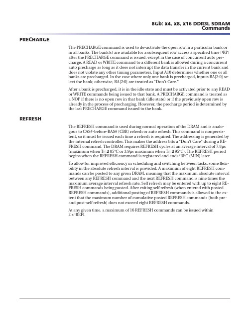
PRECHARGEThe PRECHARGE command is used to de-activate the open row in a particular bank orin all banks. The bank(s) are available for a subsequent row access a specified time (t RP)after the PRECHARGE command is issued, except in the case of concurrent auto pre-charge. A READ or WRITE command to a different bank is allowed during a concurrentauto precharge as long as it does not interrupt the data transfer in the current bank anddoes not violate any other timing parameters. Input A10 determines whether one or allbanks are precharged. In the case where only one bank is precharged, inputs BA[2:0] se-lect the bank; otherwise, BA[2:0] are treated as “Don’t Care.”After a bank is precharged, it is in the idle state and must be activated prior to any READor WRITE commands being issued to that bank. A PRECHARGE command is treated asa NOP if there is no open row in that bank (idle state) or if the previously open row isalready in the process of precharging. However, the precharge period is determined bythe last PRECHARGE command issued to the bank.REFRESHThe REFRESH command is used during normal operation of the DRAM and is analo-gous to CAS#-before-RAS# (CBR) refresh or auto refresh. This command is nonpersis-tent, so it must be issued each time a refresh is required. The addressing is generated bythe internal refresh controller. This makes the address bits a “Don’t Care” during a RE-FRESH command. The DRAM requires REFRESH cycles at an average interval of 7.8μs(maximum when T Cื 85°C or 3.9μs maximum when T Cื 95°C). The REFRESH periodbegins when the REFRESH command is registered and ends t RFC (MIN) later.To allow for improved efficiency in scheduling and switching between tasks, some flexi-bility in the absolute refresh interval is provided. A maximum of eight REFRESH com-mands can be posted to any given DRAM, meaning that the maximum absolute intervalbetween any REFRESH command and the next REFRESH command is nine times themaximum average interval refresh rate. Self refresh may be entered with up to eight RE-FRESH commands being posted. After exiting self refresh (when entered with postedREFRESH commands), additional posting of REFRESH commands is allowed to the ex-tent that the maximum number of cumulative posted REFRESH commands (both pre-and post-self refresh) does not exceed eight REFRESH commands.At any given time, a maximum of 16 REFRESH commands can be issued within2 x t REFI.Figure 38: Refresh ModeDon’t CareIndicates breakin time scale CK CK#Command CKE AddressA10BA[2:0]DQ 4DM 4DQS, DQS#4Notes: 1.NOP commands are shown for ease of illustration; other valid commands may be possi-ble at these times. CKE must be active during the PRECHARGE, ACTIVATE, and REFRESH commands, but may be inactive at other times (see Power-Down Mode (page 174)).2.The second REFRESH is not required, but two back-to-back REFRESH commands are shown.3.“Don’t Care” if A10 is HIGH at this point; however, A10 must be HIGH if more than one bank is active (must precharge all active banks).4.For operations shown, DM, DQ, and DQS signals are all “Don’t Care”/High-Z.5.Only NOP and DES commands are allowed after a REFRESH command and until t RFC (MIN) is satisfied.SELF REFRESHThe SELF REFRESH command is used to retain data in the DRAM, even if the rest of the system is powered down. When in self refresh mode, the DRAM retains data without ex-ternal clocking. Self refresh mode is also a convenient method used to enable/disable the DLL as well as to change the clock frequency within the allowed synchronous oper-ating range (see Input Clock Frequency Change (page 117)). All power supply inputs (including V REFCA and V REFDQ ) must be maintained at valid levels upon entry/exit and during self refresh mode operation. V REFDQ may float or not drive V DDQ /2 while in self refresh mode under the following conditions:•V SS < V REFDQ < V DD is maintained •V REFDQ is valid and stable prior to CKE going back HIGH •The first WRITE operation may not occur earlier than 512 clocks after V REFDQ is valid •All other self refresh mode exit timing requirements are met。
MEMORY存储芯片MT48LC4M16A2P-75C中文规格书

Power-Down ModeDDR2 SDRAM supports multiple power-down modes that allow significant power sav-ings over normal operating modes. CKE is used to enter and exit different power-down modes. Power-down entry and exit timings are shown in Figure 70 (page 120). Detailed power-down entry conditions are shown in Figure 71 (page 122)–Figure 78 (page 125).Table 44 (page 121) is the CKE Truth Table.DDR2 SDRAM requires CKE to be registered HIGH (active) at all times that an access is in progress—from the issuing of a READ or WRITE command until completion of the burst. Thus, a clock suspend is not supported. For READs, a burst completion is defined when the read postamble is satisfied; for WRITEs, a burst completion is defined when the write postamble and t WR (WRITE-to-PRECHARGE command) or t WTR (WRITE-to-READ command) are satisfied, as shown in Figure 73 (page 123) and Figure 74(page 123) on Figure 74 (page 123). The number of clock cycles required to meet t WTR is either two or t WTR/t CK, whichever is greater.Power-down mode (see Figure 70 (page 120)) is entered when CKE is registered low co-incident with an NOP or DESELECT command. CKE is not allowed to go LOW during a mode register or extended mode register command time, or while a READ or WRITE op-eration is in progress. If power-down occurs when all banks are idle, this mode is refer-red to as precharge power-down. If power-down occurs when there is a row active in any bank, this mode is referred to as active power-down. Entering power-down deacti-vates the input and output buffers, excluding CK, CK#, ODT, and CKE. For maximum power savings, the DLL is frozen during precharge power-down. Exiting active power-down requires the device to be at the same voltage and frequency as when it entered power-down. Exiting precharge power-down requires the device to be at the same volt-age as when it entered power-down; however, the clock frequency is allowed to change (see Precharge Power-Down Clock Frequency Change (page 126)).The maximum duration for either active or precharge power-down is limited by the re-fresh requirements of the device t RFC (MAX). The minimum duration for power-down entry and exit is limited by the t CKE (MIN) parameter. The following must be main-tained while in power-down mode: CKE LOW, a stable clock signal, and stable power supply signals at the inputs of the DDR2 SDRAM. All other input signals are “Don’t Care” except ODT. Detailed ODT timing diagrams for different power-down modes are shown in Figure 83 (page 131)–Figure 88 (page 135).The power-down state is synchronously exited when CKE is registered HIGH (in con-junction with a NOP or DESELECT command), as shown in Figure 70 (page 120).2Gb: x4, x8, x16 DDR2 SDRAM Power-Down ModeFigure 70: Power-DownCK CK#CommandAddress CKE DQDMDQS, DQS#Enterpower-downmode 6Exit power-down mode Don’t Care T1T2T3T4T5T6T7T8Notes: 1.If this command is a PRECHARGE (or if the device is already in the idle state), then thepower-down mode shown is precharge power-down. If this command is an ACTIVATE (or if at least one row is already active), then the power-down mode shown is active power-down.2.t CKE (MIN) of three clocks means CKE must be registered on three consecutive positive clock edges. CKE must remain at the valid input level the entire time it takes to achieve the three clocks of registration. Thus, after any CKE transition, CKE may not transition from its valid level during the time period of t IS + 2 × t CK + t IH. CKE must not transition during its t IS and t IH window.3.t XP timing is used for exit precharge power-down and active power-down to any non-READ command.4.t XARD timing is used for exit active power-down to READ command if fast exit is selec-ted via MR (bit 12 = 0).5.t XARDS timing is used for exit active power-down to READ command if slow exit is se-lected via MR (bit 12 = 1).6.No column accesses are allowed to be in progress at the time power-down is entered. If the DLL was not in a locked state when CKE went LOW, the DLL must be reset after exit-ing power-down mode for proper READ operation.2Gb: x4, x8, x16 DDR2 SDRAM Power-Down Mode。
MEMORY存储芯片MT48H16M32LFCM-75中文规格书

WRITE latency and AL, WL = AL + CWL (see Mode Register 2 (MR2) (page 135)). Exam-ples of READ and WRITE latencies are shown in Figure 53 (page 135) and Figure 55(page 136).Figure 53: READ Latency (AL = 5, CL = 6)CKCK#Command DQDQS, DQS#Don’t CareBC4Indicates breakin time scale Transitioning Data Mode Register 2 (MR2)The mode register 2 (MR2) controls additional functions and features not available in the other mode registers. These additional functions are CAS WRITE latency (CWL), AU-TO SELF REFRESH (ASR), SELF REFRESH TEMPERATURE (SRT), and DYNAMIC ODT (R TT(WR)). These functions are controlled via the bits shown in Figure 54. The MR2 is programmed via the MRS command and will retain the stored information until it is programmed again or until the device loses power. Reprogramming the MR2 register will not alter the contents of the memory array, provided it is performed correctly. The MR2 register must be loaded when all banks are idle and no data bursts are in progress,and the controller must wait the specified time t MRD and t MOD before initiating a sub-sequent operation.Address busNote: 1.MR2[18, 15:11, 8, and 2:0] are reserved for future use and must all be programmed to 0.CAS WRITE Latency (CWL)CWL is defined by MR2[5:3] and is the delay, in clock cycles, from the releasing of the internal write to the latching of the first data in. CWL must be correctly set to the corre-sponding operating clock frequency (see Figure 54 (page 136)). The overall WRITE la-tency (WL) is equal to CWL + AL (Figure 52 (page 132)).Figure 55: CAS WRITE LatencyCKCK#Command DQDQS, DQS#Don’t CareIndicates breakin time scale Transitioning Data AUTO SELF REFRESH (ASR)Mode register MR2[6] is used to disable/enable the ASR function. When ASR is disabled,the self refresh mode’s refresh rate is assumed to be at the normal 85°C limit (some-times referred to as 1x refresh rate). In the disabled mode, ASR requires the user to en-sure the DRAM never exceeds a T C of 85°C while in self refresh unless the user enables the SRT feature listed below when the T C is between 85°C and 95°C.Enabling ASR assumes the DRAM self refresh rate is changed automatically from 1x to 2x when the case temperature exceeds 85°C. This enables the user to operate the DRAM beyond the standard 85°C limit up to the optional extended temperature range of 95°C while in self refresh mode.The standard self refresh current test specifies test conditions to normal case tempera-ture (85°C) only, meaning if ASR is enabled, the standard self refresh current specifica-tions do not apply (see Extended Temperature Usage (page 173)).SELF REFRESH TEMPERATURE (SRT)Mode register MR2[7] is used to disable/enable the SRT function. When SRT is disabled,the self refresh mode’s refresh rate is assumed to be at the normal 85°C limit (some-times referred to as 1x refresh rate). In the disabled mode, SRT requires the user to en-sure the DRAM never exceeds a T C of 85°C while in self refresh mode unless the user en-ables ASR.When SRT is enabled, the DRAM self refresh is changed internally from 1x to 2x, regard-less of the case temperature. This enables the user to operate the DRAM beyond the standard 85°C limit up to the optional extended temperature range of 95°C while in self refresh mode. The standard self refresh current test specifies test conditions to normal case temperature (85°C) only, meaning if SRT is enabled, the standard self refresh cur-rent specifications do not apply (see Extended Temperature Usage (page 173)).SRT vs. ASRIf the normal case temperature limit of 85°C is not exceeded, then neither SRT nor ASR is required, and both can be disabled throughout operation. However, if the extended temperature option of 95°C is needed, the user is required to provide a 2x refresh rate during (manual) refresh and to enable either the SRT or the ASR to ensure self refresh is performed at the 2x rate.SRT forces the DRAM to switch the internal self refresh rate from 1x to 2x. Self refresh is performed at the 2x refresh rate regardless of the case temperature.ASR automatically switches the DRAM’s internal self refresh rate from 1x to 2x. Howev-er, while in self refresh mode, ASR enables the refresh rate to automatically adjust be-tween 1x to 2x over the supported temperature range. One other disadvantage with ASR is the DRAM cannot always switch from a 1x to a 2x refresh rate at an exact case temper-ature of 85°C. Although the DRAM will support data integrity when it switches from a 1x to a 2x refresh rate, it may switch at a lower temperature than 85°C.Since only one mode is necessary, SRT and ASR cannot be enabled at the same time.DYNAMIC ODTThe dynamic ODT (R TT(WR)) feature is defined by MR2[10, 9]. Dynamic ODT is enabled when a value is selected. This new DDR3 SDRAM feature enables the ODT termination value to change without issuing an MRS command, essentially changing the ODT ter-mination on-the-fly.With dynamic ODT (R TT(WR)) enabled, the DRAM switches from normal ODT (R TT,nom )to dynamic ODT (R TT(WR)) when beginning a WRITE burst and subsequently switches8Gb: x4, x8, x16 DDR3L SDRAM Mode Register 2 (MR2)。
- 1、下载文档前请自行甄别文档内容的完整性,平台不提供额外的编辑、内容补充、找答案等附加服务。
- 2、"仅部分预览"的文档,不可在线预览部分如存在完整性等问题,可反馈申请退款(可完整预览的文档不适用该条件!)。
- 3、如文档侵犯您的权益,请联系客服反馈,我们会尽快为您处理(人工客服工作时间:9:00-18:30)。
Capacitance (VCC=3.3V, f=1MHz, TA=0~70°C)
Symbol CCLK CI CIO CII Parameter Clock Capacitance Input Capacitance for CLK, CKE, Address, /CS, /RAS, /CAS, /WE, DQML, DQMU Output Capacitance Input Capacitance (A0 to A12) Min. Typ. Max. 4 5 6.5 5 Units pF pF pF pF
Note: Capacitance is sampled and not 100% tested.
Recommended DC Operating Conditions (TA=0°C ~70°C)
Symbol VDD VDDQ VIH Parameter Power Supply Voltage Power Supply Voltage (for I/O Buffer) Input Logic High Voltage Min. 3.0 3.0 2.0 -0.3 Typ. 3.3 3.3 Max. 3.6 3.6 VDD+0.3 0.8 Units V V V V
Grade
Commercial Commercial
Pb
Free Free
* EOREX reserves the right to change products or specification without notice.
Jul. 2006 1/17
元器件交易网
37
CKE
23~26, 22, 29~36
A0~A12
20, 21 18
BA0, BA1 /RAS
17
/CAS
16 39/15 2, 4, 5, 7, 8, 10, 11, 13, 42, 44, 45, 47, 48, 50, 51, 53 1,14,27/ 28,41,54 3, 9, 43, 49/ 6, 12, 46, 52 40
VIL Input Logic Low Voltage Note: * All voltages referred to VSS. * VIH (max.) = 5.6V for pulse width 3ns * VIL (min.) = -2.0V for pulse width 3ns
Jul. 2006 4/17
eorex
Pin Assignment
EM48AM1684VTC
54pin TSOP-II / (400mil × 875mil) / (0.8mm Pin pitch)
Jul. 2006 2/17
元器件交易网
eorex
Pin Description (Simplified)
EM48AM1684VTC
256Mb (4M×4Bank×16) Synchronous DRAM
Description
The EM48AM1684VTC is Synchronous Dynamic Random Access Memory (SDRAM) organized as 4Meg words x 4 banks by 16 bits. All inputs and outputs are synchronized with the positive edge of the clock. The 256Mb SDRAM uses synchronized pipelined architecture to achieve high speed data transfer rates and is designed to operate at 3.3V low power memory system. It also provides auto refresh with power saving / down mode. All inputs and outputs voltage levels are compatible with LVTTL. Available packages: TSOPII 54P 400mil.
Pin 38 19 Name CLK /CS
EM48AM1684VTC
Function (System Clock) Master clock input (Active on the positive rising edge) (Chip Select) Selects chip when active (Clock Enable) Activates the CLK when “H” and deactivates when “L”. CKE should be enabled at least one cycle prior to new command. Disable input buffers for power down in standby. (Address) Row address (A0 to A12) is determined by A0 to A12 level at the bank active command cycle CLK rising edge. CA (CA0 to CA8) is determined by A0 to A8 level at the read or write command cycle CLK rising edge. And this column address becomes burst access start address. A10 defines the pre-charge mode. When A10= High at the pre-charge command cycle, all banks are pre-charged. But when A10= Low at the pre-charge command cycle, only the bank that is selected by BA0/BA1 is pre-charged. (Bank Address) Selects which bank is to be active. (Row Address Strobe) Latches Row Addresses on the positive rising edge of the CLK with /RAS “L”. Enables row access & pre-charge. (Column Address Strobe) Latches Column Addresses on the positive rising edge of the CLK with /CAS low. Enables column access. (Write Enable) Latches Column Addresses on the positive rising edge of the CLK with /CAS low. Enables column access. (Data Input/Output Mask) DQM controls I/O buffers. (Data Input/Output) DQ pins have the same function as I/O pins on a conventional DRAM. (Power Supply/Ground) VDD and VSS are power supply pins for internal circuits. (Power Supply/Ground) VDDQ and VSSQ are power supply pins for the output buffers. (No Connection) This pin is recommended to be left No Connection on the device.
Ordering Information
Part No
EM48AM1684VTC-75F EM48AM1684VTC-7F
Organization
16M X 16 16M X 16
Max. Freq
133MHz @CL3 143MHz @CL3
Package
54pin TSOP(ll) 54pin TSOP(ll)
/WE UDQM/LDQM DQ0~DQ15 VDD/VSS VDDQ/VSSQ NC
Jul. 2006 3/17
元器件交易网
eorex
Absolute Maximum Rating
Symbol VIN, VOUT VDD, VDDQ TOP TSTG PD Item Input, Output Voltage Power Supply Voltage Operating Temperature Range Storage Temperature Range Power Dissipation
元器件交易网
eorex
Recommended DC Operating Conditions
(VDD=3.3V±0.3V, TA=0°C ~70°C) Symbol ICC1 ICC2P ICC2PS ICC2N Parameter Operating Current
元器件交易网
eorex
Features
• Fully Synchronous to Positive Clock Edge • Single 3.3V ±0.3V Power Supply • LVTTL Compatible with Multiplexed Address • Programmable Burst Length (B/L) - 1, 2, 4, 8 or Full Page • Programmable CAS Latency (C/L) - 2 or 3 • Data Mask (DQM) for Read / Write Masking • Programmable Wrap Sequence – Sequential (B/L = 1/2/4/8/full Page) – Interleave (B/L = 1/2/4/8) • Burst Read with Single-bit Write Operation • All Inputs are Sampled at the Rising Edge of the System Clock • Auto Refresh and Self Refresh • 8,192 Refresh Cycles / 64ms (7.8us)