TL1105GF160Q;中文规格书,Datasheet资料
EFM1011Q产品说明书(能效通)

SMA 无线接头母头
1) 串口波特率及无线发射功率设置 EFM1011Q 无线数据采集装置通过 SW1、 SW2、 SW3 设置串口波特率、 无线数据发射功率, 如表 4.3.1 所示:
10010 01010 11010 00110 10110 01110 11110 00001 10001 01001 11001 00101 10101 01101 11101 00011 10011 01011 11011 00111 10111 对应无线频率通道 通道 0 通道 1 通道 2 通道 3 通道 4 通道 5 通道 6 通道 7 通道 8
使用 EFM1011Q 产品,通过无线传输方式采集下行无线压力传感器、无线温湿度传感 器、无 线 液 位 传 感 器 等 测 量 参 数,并 将 采 集 到 的 数 据 按 照 顺 序 进 行 暂 存,支 持 Modbus-RTU 通信协议,通过 RS485 总线将采集到的数据上传至数据栈。 一台
2. 产品接线
SET
无线通讯指示灯 9 路指示灯
表 4.3.1 串口波特率及无线数据发射功率 SW1、 SW2、 SW3 000 100 010 110 001 101 011 111 对应串口波特率 9.6K 2.4K 4.8K 19.2K 9.6K 9.6K 9.6K 9.6K 对应无线数据发送功率 20dbm 20dbm 20dbm 20dbm 17dbm 14dbm 11dbm 8dbm
+24V/-24V A/B FG
4007-169-861
深圳市能效通网络有限公司
深圳市宝安区石岩镇吉安工业园 邮编 :518000 总机:0755-8618 5881 传真:0755-8618 5880 www.nxtone.net
美国Eaton公司GF15W型号轻型GFCI保护插座说明说明书

Page 1 of 1Electrical Sector 1123 Hwy 74 SPeachtree City, GA 30269United States /SlimGFCIEaton1000 Eaton Boulevard Cleveland, OH 44122United States Eaton is a registered trademark. All other trademarks are property of their respective owners.© 2023 EatonAll Rights Reserved Printed in USAPublication No. TD610152ENSeptember 2023AlmondTRIP INDICATORSEOL Indicator LightRESET Button Light DiagnosisOFF OFF Device is functioning properly, OR branch circuit may not have power OFF ON Device is in tripped stateBlinking or ONONDevice is in “end of life” state and must be replacedAPPLICATIONS• Arrow Hart GFCI receptacles are UL Listed and fully compliant with all of the latest UL943 Class A GFCI and UL498 requirements• GFCI protection is required wherever receptacles are near wet or damp locations, such as public bathrooms, garages, and food service areas, and all other areas mandated by the NEC DESIGN FEATURES• Slimmer design for easy installation, leaving more room for wires in the box • Automatically self‑tests periodically to ensure GFCI protection• GFCIs incorporate lock‑out functionality to protect against mis‑wired line‑load connections and GFCI circuitry damage • Wider button wells for easy TEST and RESET• Intuitive LED status indicators for trip and end of life states• Clean, modern industrial design with reduced top housing markings and neutral text direction on buttons • Meets and exceeds 10 kA short circuit testing and Underwriters Laboratories (UL) UL943 safety standards • Automatic grounding system eliminates need for bonding jumper in grounded metal enclosure, provides redundant measure of ground continuity where jumper is used • External backwire clamps provide visual confirmation of secure termination • Line side terminals are backed out and staked for fast installation COMPLEMENTARY PRODUCTSWallplatesPJS26, PJS262ADDITIONAL RESOURCESScan QR code for additionalmarketing collateralArrow Hart WebsiteBuyer’s Guide Product pageMATERIALS Housing Top: Thermoplastic, polycarbonate Bottom: Thermoplastic, PVC Strap 0.042” thick steel, zinc‑plated Line contacts 0.030” thick brass Terminal Brass/nickel‑plated steelSPECIFICATIONS ElectricalDielectric voltage: Withstands 2000V per UL 498Current interrupting: Yes, at full‑rated current Temperature rise: Max. 30ºC (86°F) after100 cycles of overload @ 150% of rated current (DC)Trip time: 0.025 seconds (Class A)Frequency: 60 Hz; Voltage: 125V; Amperage: 15A/20A, 20A feed‑throughShort circuit testing: Meets and exceeds 10 kA Maximum interrupting capacity: 20 Amps Testing & code compliance cULus Listed to UL 498 and UL 943, file no. E60120Meets all UL 943 (GFCI), UL 498 (receptacles) and applicable CSA requirements; NOM certified; Federal Specification W‑C‑596H for 20A models Environmental Flammability: Meets UL 94 requirements; V2 rated Temperature rating: ‑35ºC to 66ºC (‑31ºF to 150.8ºF)Mechanical Terminal accommodation: #14 ‑ 10 AWG Voltage ratings: Permanently marked on deviceDESCRIPTION2-pole, 3-wire grounding 15A, 125V/AC 20A, 125V/ACSTANDARD GFCI RECEPTACLES, BACK & SIDE WIRERating A V/ACNEMA Catalog no.Color suffixFeatures151255‑15R ☐GF15__B, BK, GY, LA, V, W 151255‑15R ☐GF15__–WP BK, WIncludes standard size wallplate201255‑20R ☐GF20__*B, BK, GY, LA, RD, V, WWallplate not included unless specifically stated; *FedSpec certification on 20A only.Project Name:Prepared By:Project Number:Date:Catalog Number:Type:。
电线电缆检测仪器配置标准

电线电缆检测仪器配置标准一、电线电缆各标准试验仪器1、GB/T 2951-2008、IEC60811-1-1:2001《电线和光缆绝缘和护套材料通用试验方法》仪器配置:2、GB/T3048-2008《电线电缆电性能试验方法》仪器配置:3、GB5023-2008、IEC60227-1:2003《额定电压450/750V及以下聚氯乙稀绝缘电缆》以及GB5013-2008、IEC60245-1:2003《额定电压450/750V及以下橡皮绝缘电缆》仪器配置:4、汽车和铁道用电缆仪器配置:QC/T730、QC/T413、QC/T29106、GB/T12528、GB/T5054。
1、GB14820、GB8410、TB/T1484、TB/T1507、5、特种线缆检测中心推荐设备配置:本配置方案依据GB12972、GB/T13033、JB/T2171、JB/T5332、JB/T6213、JB8734、GB/T9332、GB9333、GB/T20637等要求而编制。
6、架空绝缘电缆试验仪器配置:本配置方案依照GB12527-2008《额定电压1 kV及以下架空绝缘电缆》、GB14049-2008《额定电压10KV架空绝缘电缆》7、《航空电线电缆》试验仪器设备配置本配置方案依据国军标GJB17系列《航空电线电缆试验方法》、GJB150系列《军用装备实验室试验方法》、IEC540以及美国军用标准二、家用和类似用途电器检测中心推荐设备配置本配置方案依据GB4706、IEC60335-1《家用和类似用途电器的安全》等要求而编制。
主要针对标准中家用和类似用途电器的安全性能、电参数性能、产品设计合理性和产品结构的可靠耐用等几个方面进行测试评估,以便企业对产品进行设计和工艺改进提供依据,同时也三、家用和类似用途插头插座检测中心推荐设备配置本配置方案依据GB1002、GB1003、GB2099、IEC60884、VDE0620和UL817等要求而编制。
3680系列精密潜入杆电阻器产品说明书
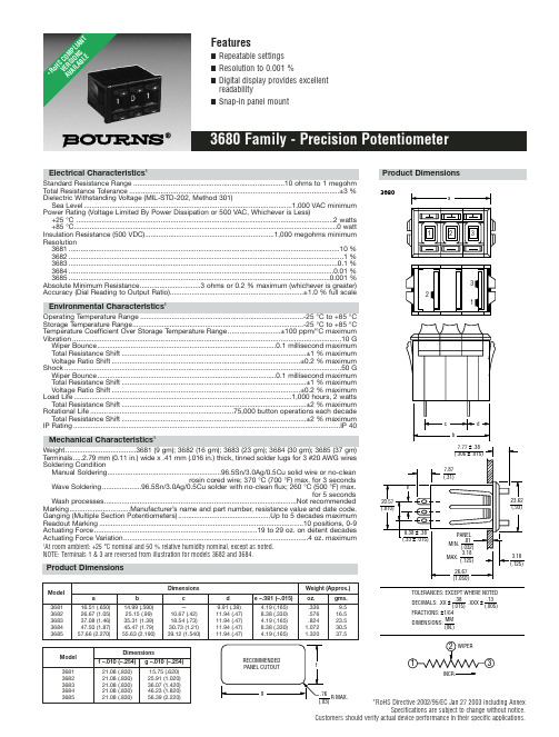
*RoHS Directive 2002/95/EC Jan 27 2003 including AnnexSpecifications are subject to change without notice.Customers should verify actual device performance in their specific applications.Electrical Characteristics 1Standard Resistance Range .............................................................................10 ohms to 1 megohm Total Resistance Tolerance...........................................................................................................±3 %Dielectric Withstanding Voltage (MIL-STD-202, Method 301)Sea Level..........................................................................................................1,000 VAC minimum Power Rating (Voltage Limited By Power Dissipation or 500 VAC, Whichever is Less)+25 °C ...................................................................................................................................2 watts +85 °C......................................................................................................................................0 watt Insulation Resistance (500 VDC)..................................................................1,000 megohms minimum Resolution3681..........................................................................................................................................10 %3682............................................................................................................................................1 %3683.........................................................................................................................................0.1 %3684.......................................................................................................................................0.01 %3685.....................................................................................................................................0.001 %Absolute Minimum Resistance...............................3 ohms or 0.2 % maximum (whichever is greater)Accuracy (Dial Reading to Output Ratio)....................................................................±1.0 % full scaleEnvironmental Characteristics1Operating Temperature Range ...................................................................................-25 °C to +85 °C Storage Temperature Range.......................................................................................-25 °C to +85 °C Temperature Coefficient Over Storage Temperature Range...........................±100 ppm/°C maximum Vibration.........................................................................................................................................10 G Wiper Bounce...........................................................................................0.1 millisecond maximum Total Resistance Shift..............................................................................................±1 % maximum Voltage Ratio Shift................................................................................................±0.2 % maximum Shock.............................................................................................................................................50 G Wiper Bounce...........................................................................................0.1 millisecond maximum Total Resistance Shift..............................................................................................±1 % maximum Voltage Ratio Shift................................................................................................±0.2 % maximum Load Life...............................................................................................................1,000 hours, 2 watts Total Resistance Shift..............................................................................................±2 % maximum Rotational Life.........................................................................75,000 button operations each decade Total Resistance Shift..............................................................................................±2 % maximum IP Rating........................................................................................................................................IP 40Mechanical Characteristics 1Weight....................................3681 (9 gm); 3682 (16 gm); 3683 (23 gm); 3684 (30 gm); 3685 (37 gm)T erminals.....2.79 mm (0.11 in.) wide x .41 mm (.016 in.) thick, tinned solder lugs for 3 #20 AWG wires Soldering ConditionManual Soldering..........................................................96.5Sn/3.0Ag/0.5Cu solid wire or no-cleanrosin cored wire; 370 °C (700 °F) max. for 3 secondsWave Soldering....................96.5Sn/3.0Ag/0.5Cu solder with no-clean flux; 260 °C (500 °F) max.for 5 secondsWash processes..................................................................................................Not recommended Marking...............................Manufacturer’s name and part number, resistance value and date code.Ganging (Multiple Section Potentiometers)...............................................Up to 5 decades maximum Readout Marking........................................................................................................10 positions, 0-9Actuating Force...................................................................................19 to 29 oz. on detent decades Actuating Force Variation..............................................................................................4 oz. maximum1At room ambient: +25 °C nominal and 50 % relative humidity nominal, except as noted.NOTE: Terminals 1 & 3 are reversed from illustration for models 3682 and 3684.3680INCR.Product DimensionsDimensionsWeight (Approx.)Model a b c d e –.381 (–.015)oz.gms.368116.51 (.650)14.99 (.590)—9.91 (.39) 4.19 (.165).3369.5368226.67 (1.05)25.15 (.99)10.67 (.42)11.94 (.47)8.38 (.330).57616.5368337.08 (1.46)35.31 (1.39)18.54 (.73)11.94 (.47) 4.19 (.165).82423.5368447.50 (1.87)45.47 (1.79)30.73 (1.21)11.94 (.47)8.38 (.330) 1.07230.5368557.66 (2.270)55.63 (2.190)39.12 (1.540)11.94 (.47)4.19 (.165)1.32037.5DimensionsModel f –.010 (–.254)g –.010 (–.254)368121.08 (.830)15.75 (.620)368221.08 (.830)25.91 (1.020)368321.08 (.830)36.07 (1.420)368421.08 (.830)46.23 (1.820)368521.08 (.830)56.39 (2.220)*Ro H S C O M P L I A N T V E R S I O N S A V A I L A B L ESpecifications are subject to change without notice.Customers should verify actual device performance in their specific applications.Recommended Part NumbersBOLDFACE LISTINGS ARE IN STOCK AND READILY AVAILABLE THROUGH DISTRIBUTION.FOR OTHER OPTIONS CONSULT FACTORY.RoHS IDENTIFIER:L =COMPLIANTBLANK =NON-COMPLIANTREV. 05/07。
ML110-ML160零件手册

MLG-110G MLG-132G MLG-160G PARTS MANUAL
零件手册
在安装或第一次起动压缩机之前,请仔细阅读本手册,清楚了解 压缩机的有关知识以及操作维修的注意事项。 请把本手册与机器一起移交使用者。 本技术手册内有重要的安全信息,应一直与压缩机一起保存。
ATC32201
第一章 引言
SECTION 1 INTRODUCTION
如何使用本零件手册 1.参考目录,找出所需章节。 2.翻到所需章节,并参照零件图的目录,找到该零件所属系统的所在页。 3.按序号辨别出该零件在图上的位置。 定购零件
HOW TO USE THIS PARTS MANUAL
1. Refer to the index and find the Section. 2. Turn to the Section and refer to the table of Connects to locate the
序号 No.
8 9 10 11 12 13 14 15 16 17 18 19 19A 20
零件号 CPN
ATC20080 99271033 S1111640 35255819
—— 39167150 39326483 S1111640 92539311 39253992 95239929 39112362 22060701 42870550 95022125 95022125 H0059310
MOTOR,GEARCASE AND GEAR SET
数量
说明
QTY. 1 6 1 1 1 1 1 1 1 1 2 1 1 14 1 1 1
desired illustrations. 3. Locate the part on the illustration by visual identification and the
FA11045_LC1-W;FA10653_LC1-RS;FA10654_LC1-REC;FA10655_LC1-D;FA10652_LC1-M;中文规格书,Datasheet资料

75 %
50 %
25 %
0% 60 50 40 30 20 10 0 -10 -20 -30 -40 -50 -60
EULUMDAT & IES FILES AVAILABLE BY REQUEST
© Ledil Oy – PRELIMINARY - Subject to change without prior notice Ledil Oy Tehdaskatu 13 FIN-24100 SALO, Finland
Relative Intensity of LC1-M 100 %
75 %
50 %
25 %
0% 40 30 20 10 0 Angle
© Ledil Oy – PRELIMINARY - Subject to change without prior notice Ledil Oy Tehdaskatu 13 FIN-24100 SALO, Finland
/
email: ledil@ FAX: +358-2-733 8001
2010-08-02
LEDIL F’FORM OPTICS
Relative Intensity of FA11045_LC1-W-Tape 100 %
/
-10
-20
-30
-40
email: ledil@ FAX: +358-2-733 8001
2010-08-02
LEDIL F’FORM OPTICS
Relative Intensity of LC1-REC 100 %
75 %
50 %
25 %
0% 30 20 10 0 -10 -20 -30
Endress+Hauser Liquiphant M FTL50, FTL50H, FTL51,

Products Solutions ServicesSafety Instructions Liquiphant M FTL50, FTL50H, FTL51, FTL51HATEX, IECEx:Ex ia IIC GaXA00064F-G/00/EN/16.21715404802021-08-30Liquiphant M FTL50, FTL50H, FTL51, FTL51H XA00064F-G Liquiphant M FTL50, FTL50H, FTL51, FTL51HTable of contentsAbout this document (4)Associated documentation (4)Supplementary documentation (4)Manufacturer's certificates (4)Manufacturer address (5)Other standards (5)Extended order code (5)Safety instructions: General (8)Safety instructions: Special conditions (9)Safety instructions: Installation (9)Temperature tables (13)Connection data (16)Endress+Hauser3XA00064F-G Liquiphant M FTL50, FTL50H, FTL51, FTL51H 4Endress+HauserAbout thisdocumentThis document has been translated into several languages. Legally determined is solely the English source text.The document translated into EU languages is available:•In the download area of the Endress+Hauser website: -> Downloads -> Manuals and Datasheets ->Type: Ex Safety Instruction (XA) -> Text Search: …•In the Device Viewer: -> Product tools ->Access device specific information -> Check device features If not yet available, the document can be ordered.Associated documentationThis document is an integral part of the following Operating Instructions:•KA00143F/00, KA00163F/00 (FTL50, FTL51)•KA00144F/00, KA00164F/00 (FTL50H, FTL51H)Supplementary documentationExplosion-protection brochure: CP00021Z/11The Explosion-protection brochure is available:•In the download area of the Endress+Hauser website: -> Downloads -> Brochures and Catalogs -> Text Search: CP00021Z •On the CD for devices with CD-based documentation Manufacturer's certificatesEU Declaration of Conformity Declaration Number:EG99021The EU Declaration of Conformity is available:In the download area of the Endress+Hauser website: -> Downloads -> Declaration -> Type: EU Declaration -> Product Code: ...EU type-examination certificate Certificate number:KEMA 99 ATEX 0523 X List of applied standards: See EU Declaration of Conformity.Liquiphant M FTL50, FTL50H, FTL51, FTL51H XA00064F-G Endress+Hauser 5IEC Declaration of Conformity Certificate number:IECEx DEK 15.0028X Affixing the certificate number certifies conformity with the following standards (depending on the device version):•IEC 60079-0 : 2017•IEC 60079-11 : 2011•IEC 60079-26 : 2021Manufacturer addressEndress+Hauser SE+Co. KG Hauptstraße 179689 Maulburg, Germany Address of the manufacturing plant: See nameplate.Other standardsAmong other things, the following standards shall be observed in their current version for proper installation:•IEC/EN 60079-14: "Explosive atmospheres - Part 14: Electrical installations design, selection and erection"•EN 1127-1: "Explosive atmospheres - Explosion prevention and protection - Part 1: Basic concepts and methodology"Extended order codeThe extended order code is indicated on the nameplate, which is affixed to the device in such a way that it is clearly visible. Additional information about the nameplate is provided in the associated Operating Instructions.Structure of the extended order code FTL5x(H)–*************+A*B*C*D*E*F*G*..(Device type)(Basic specifications)(Optional specifications)* =Placeholder At this position, an option (number or letter) selected from the specification is displayed instead of the placeholders.Basic specifications The features that are absolutely essential for the device (mandatory features) are specified in the basic specifications. The number ofXA00064F-G Liquiphant M FTL50, FTL50H, FTL51, FTL51H 6Endress+Hauserpositions depends on the number of features available.The selected option of a feature can consist of several positions.Optional specifications The optional specifications describe additional features for the device (optional features). The number of positions depends on the number of features available. The features have a 2-digit structure to aid identification (e.g. JA). The first digit (ID) stands for the feature group and consists of a number or a letter (e.g. J = Test, Certificate). The second digit constitutes the value that stands for the feature within the group (e.g. A = 3.1 material (wetted parts), inspection certificate).More detailed information about the device is provided in the following tables. These tables describe the individual positions and IDs in the extended order code which are relevant to hazardous locations.Extended order code: Liquiphant M The following specifications reproduce an extract from the product structure and are used to assign:•This documentation to the device (using the extended order code on the nameplate).•The device options cited in the document.Device type FTL50, FTL50H, FTL51, FTL51H Basic specificationsLiquiphant M FTL50, FTL50H, FTL51, FTL51H XA00064F-GEndress+Hauser7XA00064F-G Liquiphant M FTL50, FTL50H, FTL51, FTL51H 8Endress+HauserOptional specifications No options specific to hazardous locations are available.Safety instructions:General•The device is intended to be used in explosive atmospheres as defined in the scope of IEC 60079-0 or equivalent national standards. If no potentially explosive atmospheres are present or if additional protective measures have been taken: The device may be operated according to the manufacturer's specifications.•Staff must meet the following conditions for mounting, electrical installation, commissioning and maintenance of the device:•Be suitably qualified for their role and the tasks they perform •Be trained in explosion protection •Be familiar with national regulations •Install the device according to the manufacturer's instructions and national regulations.•Do not operate the device outside the specified electrical, thermal and mechanical parameters.•Only use the device in media to which the wetted materials have sufficient durability.•Avoid electrostatic charging:•Of plastic surfaces (e.g. enclosure, sensor element, special varnishing, attached additional plates, ..)•Of isolated capacities (e.g. isolated metallic plates)•Refer to the temperature tables for the relationship between the permitted ambient temperature for the sensor and/or transmitter,depending on the range of application and the temperature class.•Modifications to the device can affect the explosion protection and must be carried out by staff authorized to perform such work by Endress+Hauser.•The probe is made of stainless steel or high corrosion-resistant alloy of thickness ≥ 1 mm.Liquiphant M FTL50, FTL50H, FTL51, FTL51H XA00064F-G Endress+Hauser 9Safety instructions:Special conditions•Limitations of the maximum ambient temperature at the electronics enclosure may be required dependent on device configuration,process temperatures and temperature classification.•Details of limitations: → 13, "Temperature tables".•To avoid electrostatic charging: Do not rub surfaces with a dry cloth.•In the event of additional or alternative special varnishing on the enclosure or other metal parts or for adhesive plates:•Observe the danger of electrostatic charging and discharge.•Do not install in the vicinity of processes (≤ 0.5 m) generating strong electrostatic charges.Basic specification, Position 8, 9 = x6Covers with glass window not permitted.Basic specification, Position 8, 9 = x5, x7Avoid sparks caused by impact and friction.Safety instructions:InstallationBasic specification, Position 7 = D, 5, 6, 7, 81A Zone 01Tank; Zone 02Electronic insert 3Enclosure 4Basic specification, Position 7 = 5, 6, 7, 8:Associated intrinsically safe power supply units Basic specification, Position 7 = D:Only associated intrinsically safe power supply unit FML621 from Endress+HauserXA00064F-G Liquiphant M FTL50, FTL50H, FTL51, FTL51H 10Endress+Hauser Basic specification, Position 7 = A2A Zone 01Tank; Zone 02Electronic insert 3Enclosure 4Permitted terminating resistor Ex ia IIC 5Certified associated apparatus 6Power supply 7Potential equalization •Connect the device using suitable cable and wire entries of protection type "Intrinsic safety (Ex i)".•Continuous service temperature of the connecting cable: ≥ T a +5 K.•Perform the following to achieve the degree of protection IP66/67:•Screw the cover tight.•Mount the cable entry correctly.•Seal unused entry glands with approved sealing plugs that correspond to the type of protection.•Observe the pertinent guidelines when interconnecting intrinsically safe circuits.•Connection of intrinsically safe PROFIBUS devices: 10 devices.Liquiphant M FTL50, FTL50H, FTL51, FTL51H XA00064F-G Endress+Hauser 11•Observe the maximum process conditions according to the manufacturer's Operating Instructions.•At high medium temperatures, note flange pressure load capacity as a factor of temperature.•Install the device to exclude any mechanical damage or friction during the application. Pay particular attention to flow conditions and tank fittings.•Support extension tube of the device if a dynamic load is expected.Accessory: Sliding sleeve The sliding sleeve can be used for a continuous setting of the switch point (see Operating Instructions).Intrinsic safety •The device is only suitable for connection to certified, intrinsically safe equipment with explosion protection Ex ia.•The intrinsically safe input power circuit of the device is isolated from ground. The dielectric strength is at least 500 V rms .Potential equalization •Integrate the device into the local potential equalization.•Grounding the screen, see the following figure.XA00064F-G Liquiphant M FTL50, FTL50H, FTL51, FTL51H Basic specification, Position 7 = A3A Version 1: Use small capacitors (e.g. 1 nF, 1500 V dielectric strength,ceramic). Total capacitance connected to the screen may not exceed 10 nF.B Version 21Terminating resistor2Distributor/T box3Screen insulated4Supply unit/Segment coupler5Potential equalization (secured in high degree)6Field device12Endress+HauserLiquiphant M FTL50, FTL50H, FTL51, FTL51H XA00064F-G Endress+Hauser 13Temperature tablesDescription notesUnless otherwise indicated, the positions always refer to the basic specification.1st column: Position 5, 6 = Ax, Bx, ...2nd column: Temperature classes T6 (85 °C) to T1 (450 °C)Column P1 to P5: Position (temperature value) on the axes of the derating •T a : Ambient temperature in °C •T p : Process temperature in °CZone 0Zone 0Zone 0XA00064F-G Liquiphant M FTL50, FTL50H, FTL51, FTL51H14Endress+HauserOutside Zone 0Outside Zone 0OutsideZone 0Position 7 = A, D, 5, 71)Only in connection with Position 8, 9 = x6Liquiphant M FTL50, FTL50H, FTL51, FTL51H XA00064F-G Position 7 = 6, 81)Only in connection with Position 8, 9 = x6Endress+Hauser15XA00064F-G Liquiphant M FTL50, FTL50H, FTL51, FTL51H 16Endress+HauserConnection dataBasic specification, Position 7 = D, 5, 6, 7, 8Associated intrinsically safe power supply unit with max. electrical specifications below the characteristic values of the electronic insertsOnly associated intrinsically safe power supply unit FML621 from Endress+HauserLiquiphant M FTL50, FTL50H, FTL51, FTL51H XA00064F-G Endress+Hauser 17Basic specification, Position 7 = A Certified intrinsically safe fieldbus (PROFIBUS PA), in accordance with the FISCO Modell, with the following maximum valuesCertified intrinsically safe circuit with the following maximum values*71540480*71540480。
DATACARD SD160

DATACARD® SD160™ CARD – PRINTER SPECIFICATIONS*Ribbon type and number of panels; Y=Yellow, M=Magenta, C=Cyan, K=Black, T=Inline Topcoat, HQ=High QualityEntrust Datacard, CD800, StickiCard, ID Centre and Intelligent Supplies Technology are trademarks, registered trademarks and/or service marks of Entrust Datacard Corporation in the United States and/or other countries. Microsoft, Windows, Windows Server and Windows Vista are registered trademarks of Microsoft Corporation. iCLASS is a registered trademark of HID Global Corporation. Kensington is a registered trademark of ACCO Brands Corporation. EcoPure is a registered trademark owned by Bio-Tec Environmental LLC. Names and logos on cards are fictitious. Any similarity to actual names, trademarks or tradenames is coincidental. Entrust Datacard Corporation in the United States and/or other countries.©2019 Entrust Datacard Corporation. All rights reserved. DS20-1002-001SD160™ PRINTER STANDARD FEATURESPrint technologyDirect-to-card dye-sublimation/resin thermal transfer Print capabilities O ne-sided, edge-to-edge printingFull-color and monochrome printing capability Edge-to-edge rewritable printing capabilityAlphanumeric text, logos and digitized signatures Variety of bar codes: 1D/2D bar code images Printer pooling/sharing UV Printing Print resolution300 dots per inch, 256 shades per color panel High-quality mode: 300 x 600 dots per inch; enhanced text, bar code and graphics printing 300 x 1200 dots per inch; enhanced text and bar code printing Print qualityAbility to conform to sRGB standard Flexible color management options Print speedFull-color printing: up to 150 cards per hour, single-sided (YMCKT*)Monochrome printing: up to 500 cards per hour, one-sided (black HQ*)Rewritable printing up to 14 seconds per card Printer memory 128 MB standard Card capacityAutomatic feed: 100-card input for 0.030 in. (0.76 mm) cards; 25-card output standard Front exception card slot Printer displayPrinter status messages Multiple backlight settingsInternational languages available: English, Spanish, German, Italian and Japanese Printer driverAdjustable color controls with image preview Pre-set area to block printing on magnetic stripe, with escapes for custom areas UtilizesWindows® based technology for high-fidelity printingSecure disabling of card remakeSoftware Development Kit (SDK) for Windows operating system printer driverUser interface languages available: English, Spanish, German, Italian, Japanese, Traditional Chinese, Portuguese, Korean and Arabic User-friendly operationPrinter messages display on LCD panel Graphical display on Windows 7, 8, XP, SP3 and 2000 operating systemsEasy, fast installationUser-friendly operation Printer messages display on LCD panelGraphical display on Windows 7, 8, XP, SP3 and 2000 operating systems Easy, fast installationCard remake standard with cancel option Operator-replaceable printhead Front panel soft power buttonDatacard® Certified Supplies featuring Intelligent Supplies Technology™Automatic identification and validation for ribbons Adjustable low ribbon and cleaning cycle alerts Ribbon saver Warranties24-month standard depot warranty24-month printhead warranty (no pass restrictions) F or India and South Asia, 18-month standard depot warranty; 12-month print head warrantySD160 PRINTER OPTIONSMagnetic stripe encoding (field upgradable) ISO 7811 three-track option (high- and low-coercivity)JIS Type II single-track optionSupport for standard and custom data formats End-user upgradeable optionsExtended 100-card output hopper Extended 200-card input hopper KL-style security lock for printer Printer cleaning supplies Print ribbon kits - colorFull-color with resin black and topcoat panel, YMCKT*, 250 imagesFull-color short panel with resin black and topcoat panel, ymcKT*, 650 imagesResin black with inline double topcoat panel on front, topcoat panel on back, KTT*, 750 images Full color with resin black, topcoat and UV panel, YMCKFT, 300 imagesPrint ribbon kits - monochromeResin black HQ* (high quality), 500 imagesResin black HQ* (high quality), dark blue, white, red, green, silver, gold, metallic silver, metallic gold, 1500 imagesNew, improved scratch-off, 1500 imagesSD160 PRINTER SPECIFICATIONSPhysical dimensionsL 15.4 in. x W 6.9 in. x H 8.8 in. (39.1 cm x 17.5 cm x 22.4 cm)Weight8.1lbs (3.7kg)Electronic requirements 100/120V, 50/60 Hz 220/240V, 50/60 Hz Plastic cards acceptedISO ID-1/CR-80 size cards;3.370 in. x 2.125 in. (85.6 mm x 53.98 mm) PVC with glossy laminate surfaceSelect key fob cards (ISO ID-1/CR-80 size cards) D atacard® StickiCard™ adhesive-backed plastic cardsCard thickness accepted0.010 in. to 0.037 in. (0.254 mm to 0.939 mm)Operating environment60˚F to 95˚F (15˚C to 35˚C)20% to 80% non-condensing humidity Storage environment5˚F to 140˚F (-15˚C to 60˚C)10% to 90%, non-condensing humidity ConnectivityBidirectional USB 2.0 high speed Agency approvalscULus, FCC, I.C., CE, Ctick, VCCI, RoHS, WEEE, CCC, KCCEnvironment/energy-saving featuresBiodegradable supply cores made with EcoPure® additiveRecyclable enclosure plastics (marked with recycle symbol per Resin Identification Code) Recyclable packaging Included with SD160 printerPrinter driver CD, Quick Install Guide and warranty Complimentary TruCredential™ Express identifcation software Cleaning swab (5/pk) Cleaning roller spindle USB cable Power supplyPower cord (region-specific)Corporate Headquarters Phone: +1 952 933 1223 ************************。