GM8387C,GM8388C双像素LDI发送器与接收器
超米特电子有限公司产品说明书

1US Headquarters TEL +(1) 781-935-4850FAX +(1) 781-933-4318 • Europe TEL +(44) 1628 404000FAX +(44) 1628 404090Asia Pacific TEL +(852) 2 428 8008FAX +(852) 2 423 8253South America TEL +(55) 11 3917 1099FAX +(55) 11 3917 0817Superior elongation and tensilestrength help to prevent tearing in use due to mishandling. Typical properties for CHO-SEAL 1310 and 1273 materi-al are shown on pages 33 and 32respectively.High Shielding PerformanceCHO-SEAL 1310 material provides more than 80 dB of shielding effectiv-ness from 100 MHz to 10 GHz, while CHO-SEAL 1273 material provides more than 100 dB.Low Volume ResistivityBoth materials have exceptionally low volume resistivity, which makes them well suited for grounding appli-cations in which a flexible electrical contact is needed.Low Compression GasketSpacer gaskets are typicallydesigned to function under low deflec-tion forces. Chomerics uses design tools such as Finite Element Analysis (FEA) to accurately predict compres-sion-deflection behavior of various cross section options. Refer to page16.LCP Plastic SpacerLiquid crystal polymer (LCP)spacers, including those made with Vectra A130 material, provide aCHO-SEAL ®1310 or 1273Conductive ElastomersWith EMI spacer gaskets, shielding and grounding are provided by Chomerics’CHO-SEAL 1310 and 1273 conductive elastomers, specifi-cally formulated for custom shape molded parts. They provide excellent shielding and isolation against electro-magnetic interference (EMI), or act as a low impedance ground path between PCB traces and shielding media. Physically tough, these elas-tomers minimize the risk of gasket damage, in contrast to thin-walled extrusions or unsupported molded gaskets.Silicone-based CHO-SEAL 1310and 1273 materials offer excellent resistance to compression set over a wide temperature range, resulting in years of continuous service. CHO-SEAL 1310 material is filled with silver-plated-glass particles, while 1273 utilizes silver-plated-copper filler to provide higher levels of EMI shielding effectiveness.EMI Spacer GasketsThe unique design of Chomerics’EMI spacer gaskets features a thin plastic retainer frame onto which a conductive elastomer is molded. The elastomer can be located inside or outside the retainer frame, as well as on its top and bottom surface. EMI spacer gaskets provide a newapproach to designing EMI gaskets into handheld electronics such as dig-ital cellular phones. Board-to-board spacing is custom designed to fit broad application needs. Customized cross sections and spacer shapes allow for very low closure forcerequirements and a perfect fit in any design or device.Robotic InstallationSpacer gaskets can be installed quickly by robotic application. Integral locater pins in the plastic spacer help ensure accuratepositioning in both manual and pick-and-place assembly. Benefits include faster assembly and lower labor costs.The integrated conductive elastomer/plastic spacer gasket is a low cost,easily installed system for providing EMI shielding and grounding in small electronic enclosures.Figure 1Single Piece EMI Gasket/Locator PinsCHO-SEAL 1310 or 1273 Conductive Elastomer (Inside)Plastic Spacer Around Outsideor InsideApplications for EMI Spacer GasketsThe spacer gasket concept is especially suited to digital and dual board telephone handsets or other handheld electronic devices. It provides a low impedance path between peripheral ground traces on printed circuit boards and components such as:•the conductive coating on a plastic housing•another printed circuit board •the keypad assemblyTypical applications for EMI spacer gaskets include:•Digital cellular, handyphone and personal communications services (PCS) handsets •PCMCIA cards•Global Positioning Systems (GPS)•Radio receivers•Other handheld electronics, e.g.,personal digital assistants (PDAs)•Replacements for metal EMI shield-ing “fences” on printedcircuit boards in wireless tele-communications devicesstable platform for direct, highprecision molding of conductive elas-tomers. The Vectra A130 material described in Table 1 has excellent heat deflection temperature character-istics (489°F, 254°C). For weight con-siderations, the LCP has aspecific gravity of only 1.61. This plas-tic is also 100% recyclable.Typical EMI Spacer Gasket Design ParametersThe EMI spacer gasket concept can be considered using the design parameters shown in Table 2. Some typical spacer gasket profiles are shown below.Figure 2Typical Spacer Gasket Profiles3US Headquarters TEL +(1) 781-935-4850FAX +(1) 781-933-4318 • Europe TEL +(44) 1628 404000FAX +(44) 1628 404090Asia Pacific TEL +(852) 2 428 8008FAX +(852) 2 423 8253South America TEL +(55) 11 3917 1099FAX +(55) 11 3917 0817Finite Element AnalysisChomerics, a division of the Parker Hannifin Corporation’s Seal Group, is the headquarters of Parker Seal’s Elastomer Simulation Group. This unit specializes in elastomer finite element analysis (FEA) using MARC K6 series software as a foundation for FEA capability.Benefits of FEA include:•Quickly optimizing elastomer gasket designs•Allowing accurate predictions of alternate elastomer design concepts •Eliminating extensive trial and error prototype evaluationTypical use of FEA in EMI spacer gasket designs is to evaluate the force vs. deflection requirements of alternate designs.For example, onespacer design features a continuous bead of con-ductive elastomer molded onto a plastic spacer. An alternative designemploys an “interrupted bead,” where the interrup-tions (gaps left on the plastic frame) are sized to maintain the requiredlevel of EMI shielding. Figure 4illustrates these alternative designs.Gasket DeflectionFigure 5 compares the effect of continuous and interrupted elastomer gasket designs in terms of the force required to deflect the conductive elastomer. This actual cellular handset application required a spacer gasket with interrupted bead to meet desired deflection forces.Chomerics Designand Application ServicesChomerics will custom design a spacer for your application. Advice,analysis and design assistance will be provided by Chomerics Applications and Design engineers at no additional fee. Contact Chomerics directlyat the locations listed at the bottom of the page.Figure 3FEA Example of an EMISpacer Gasket Cross SectionFigure 4Continuous (top) and InterruptedElastomer GasketsFigure 5Typical Spacer Gasket Deflection。
GM3188数传电台技术手册-DM4800-9600

无线数传电台技术手册DATA COMMUNICATION RADIO USER’S GUIDE北京德利恒通通讯科技有限公司北京市丰台科技园区海鹰路5号赛欧创业孵化广场710室() TEL:010-FAX:010-Email:xianwei82@DM4800无线智能MODEM 技术手册GM3188无线数传电台技术手册1概述无线数传电台是全数字化智能数据通信终端设备,该产品采用数字信号处理和先进的数据通信技术,实现高速数据传输。
GM3188型数传电台是将DM4800/9600无线智能调制解调器嵌入到MOTOROLA的GM3188电台中,将现有的模拟VHF/UHF超短波电台升级为支持高速(4800/9600bps)数据传输的数字电台。
GM3188型无线数传电台可以和各种数据设备接口,包括各种远程终端设备RTU (Remote Terminal Units )、PLC (Programmable Logic Controllers ) 、计算机、工业仪表及GPS等,为这些设备提供可靠的无线数据通信链路。
2GM3188的应用2.1 应用领域2.2 应用模式GM3188的典型应用模式包括一个主站系统和多个子站系统。
这是一个典型的SCADA (Supervisory Control and Data Acquisition)系统。
在该系统中,GM3188和常规的FM 电台结合在一起,提供主站计算机与子站的远程终端设备RTU (Remote Terminal Units) 或是其它的数据采集设备之间的无线数据通信链路。
GM3188采用的是透明的数据传输协议,因而对中心计算机和RTU设备而言,相当于存在一条有线的串行电缆。
原来的为有线通信设计的协议不需要做大的改动。
基于无线数据通信的SCADA系统和传统的基于有线/专线的SCADA系统相比,有北京德利恒通通讯科技有限公司 第1页共7页一系列优点,如架设方便,维护方便,建造费用低,扩容方便等;其中最大的优点是大大节省了申请和使用电话专线所需的高额费用。
基于单片机的电话远程控制家电系统-毕业设计

黑龙江科技学院2011届本科毕业论文(设计)论文题目:基于单片机的电话远程控制系统目录1绪论 (4)2系统设计原理 (6)2.1 硬件功能分析 (6)2.2 软件模块分析 (8)3 系统硬件电路设计 (9)3.1振铃检测电路 (9)3.1.1电路工作原理 (9)3.1.2 电路图设计 (9)3.2 摘挂机控制电路 (9)3.2.1电路工作原理 (9)3.2.2 电路图设计 (10)3.2.3 核心AT89C2051芯片介绍 (11)3.3 双音频DTMF解码电路 (12)3.3.1 电路工作原理 (12)3.3.2 电路图设计 (13)3.3.3 核心MT8870芯片介绍 (13)3.3.4 MT8870解码表 (14)3.4 家用电器控制电路 (15)3.4.1 电路工作原理 (15)3.4.2 电路图设计 (15)3.4.3 核心74LS273芯片介绍 (16)3.5 信息反馈电路 (17)3.5.1 电路工作原理 (17)3.5.2 音乐集成电路芯片介绍 (18)3.5.3音乐集成电路使用中的注意事项 (18)4系统软件设计 (19)4.1 软件设计原理 (19)4.2 系统程序设计流程图 (19)5结束语 (20)参考文献 (21)附录一电路总图 (22)附录二程序清单 (23)基于单片机的电话远程控制系统摘要:随着通讯产业的迅速发展,电话机已经走进了千家万户,但是利用电话机进行远程控制的技术却没有多少实质性的进展.如何将电话远程控制用于日常生活中正是本文所要研究的课题,众所周知,近几年通信和电子信息技术行业有了长足发展,本文设计了一种电话远程控制系统,该系统以AT89C2051单片机和MT8870双音多频解码集成电路为核心,借助公共电话网络,通过电话实现对远程设备智能化控制。
文章介绍了系统的组成、工作原理及程序设计方法。
对“振铃检测、模拟摘挂机控制、双音频解码,语音提示及家用电器控制”等电路作了详细的说明。
斑马技术公司DS8108数字扫描仪产品参考指南说明书
ct8224c-3 规格书
ct8224c-3 规格书ct8224c-3是一款高性能的8通道光纤收发器,该产品采用数字光纤传输技术,支持高达2.5Gbps的宽带传输,可满足各种复杂的光纤传输应用需求,包括视频监控、音频传输、数据传输等。
产品特点1.支持8通道光纤传输,满足高通量数据传输需求2.支持点对点、点对多点、多点对多点等多种光纤拓扑结构的应用3.支持多种传输模式,如单模、多模等,并可自动适应不同光纤类型4.支持自动波长检测功能,减少光纤连接的频繁调整5.支持热插拔,方便现场安装、调试与维护6.支持自动负载均衡,实现数据传输的稳定、高效7.支持多种应用场景,如广播电视、数据中心、安防监控等8.支持可编程的参数配置,方便用户自定义设置技术规格1.光纤接口:SC接口2.传输速率:2.5 Gbps3.传输距离:10km4.传输模式:单模/多模自适应5.工作温度范围:-20℃至+70℃6.电源:AC100~240V7.功耗:≤5W8.颜色:黑色应用场景ct8224c-3光纤收发器广泛应用于各类高速数据传输场景,特别适用于广播电视、数据中心、安防监控等领域。
1.广播电视:可以实现高质量、高速的音视频传输,满足广播电视场景下的数据传输需求2.数据中心:可以实现数据中心内、数据中心间的高速数据传输,支持多种光纤拓扑结构的应用,可满足数据中心的需求3.安防监控:可以将监控摄像头与监控中心通过光纤互联,实现高清、高速的监控数据传输,可满足安防监控中心、公共安全场所等场景下的需求。
4.其他:ct8224c-3光纤收发器支持多种应用场景,如医疗器械、高速公路监控、航空航天等。
产品优势1.高速稳定:采用宽带传输技术,支持高达2.5Gbps的宽带传输,实现高速、稳定的数据传输。
2.可靠性强:支持多种光纤拓扑结构,自动适应不同光纤类型,具有快速恢复和自动负载均衡等特性,能够确保数据的可靠性。
3.易于安装:支持热插拔功能,可以方便地现场安装、调试与维护。
GM388电台咪接头定义及电台编程适配器研制
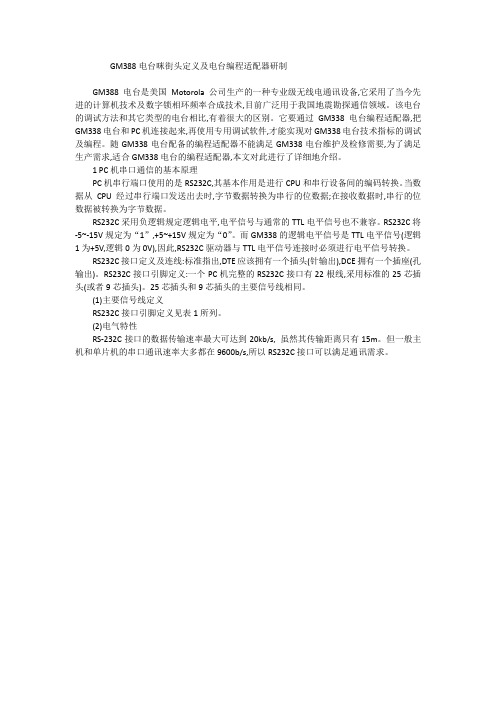
GM388电台咪街头定义及电台编程适配器研制GM388电台是美国Motorola公司生产的一种专业级无线电通讯设备,它采用了当今先进的计算机技术及数字锁相环频率合成技术,目前广泛用于我国地震勘探通信领域。
该电台的调试方法和其它类型的电台相比,有着很大的区别。
它要通过GM338电台编程适配器,把GM338电台和PC机连接起来,再使用专用调试软件,才能实现对GM338电台技术指标的调试及编程。
随GM338电台配备的编程适配器不能满足GM338电台维护及检修需要,为了满足生产需求,适合GM338电台的编程适配器,本文对此进行了详细地介绍。
1 PC机串口通信的基本原理PC机串行端口使用的是RS232C,其基本作用是进行CPU和串行设备间的编码转换。
当数据从CPU经过串行端口发送出去时,字节数据转换为串行的位数据;在接收数据时,串行的位数据被转换为字节数据。
RS232C采用负逻辑规定逻辑电平,电平信号与通常的TTL电平信号也不兼容。
RS232C将-5~-15V规定为“1”,+5~+15V规定为“0”。
而GM338的逻辑电平信号是TTL电平信号(逻辑1为+5V,逻辑0为0V),因此,RS232C驱动器与TTL电平信号连接时必须进行电平信号转换。
RS232C接口定义及连线:标准指出,DTE应该拥有一个插头(针输出),DCE拥有一个插座(孔输出)。
RS232C接口引脚定义:一个PC机完整的RS232C接口有22根线,采用标准的25芯插头(或者9芯插头)。
25芯插头和9芯插头的主要信号线相同。
(1)主要信号线定义RS232C接口引脚定义见表1所列。
(2)电气特性RS-232C接口的数据传输速率最大可达到20kb/s, 虽然其传输距离只有15m。
但一般主机和单片机的串口通讯速率大多都在9600b/s,所以RS232C接口可以满足通讯需求。
(3)接口的典型应用大多数计算机系统与终端单元之间只需使用少量几根信号线连接即可工作,见图1所示。
关于车载电台的选购

关于车载电台的选购一、车载电台的选购原则:1、车载电台的特点:关于车载电台与手台的区别以及车载电台的分类,我们将在另外的帖子里详细讨论。
在此,我们只简述一下适合我们车腿使用的车台的特点:A、功率大,通联距离远。
目前市场上适合我们车腿使用的车台在70厘米波段的发射功率一般在25-50W之间,比手台要大很多倍,通联范围也相应增大很多。
B、功能强大,技术指标好,坚固耐用。
一般车台都具有很多的实用功能,使用上方便灵活。
同时他们的技术指标和质量也高于一般手台(主要指国产手台),使用寿命很长。
C、固定安装,可以在车辆、家庭和办公场所使用。
车载电台不便于随身携带使用,适于在车辆和房间内固定安装使用。
D、需要大功率专业电源供电。
车载电台一般需要专业通讯电源提供13.8V的直流电,供电电流一般应大于20A。
在车内安装时可以直接接在12V汽车电平上使用。
E、车载电台自身不配备天线,但可以接驳任何类型的天线。
F、双段和多段车载电台一般具有很宽的接收范围和双段/多段发射能力,可以监听许多频段。
同时他们中大多数还具有双监听/双显示功能。
G、新一代的车载电台一般都具有机身/面板分离功能,可以方便地在车内任何地方安装、使用。
2、我们车腿的一般选购原则:A、具有业余无线电爱好者可以使用的收发频率范围。
比如,单段车台要能够在430-440MHZ的频率范围内收发。
当然如果是双段车台要可以在U/V段具有收发功能。
B、接收灵敏度好。
C、操作简便、使用灵活。
可以手制频。
D、适合的发射功率,一般在25W以上。
E、在较高的性价比范围内,具有尽量多的使用功能和好的应用口碑。
F、最好支持上中继、亚音、差转功能。
[[i] 本帖最后由疯骥于 2006-7-10 11:21 编辑 [/i]]疯骥 2006-7-10 09:56二、目前市场上的主流车载电台:1、 Yeasu(八重洲) FT-7800R:FT-7800R是目前市场上性价比最高的车载电台,也是车腿们最热门的基本配置。
SPVA 24 7操作多功能显示器说明书

SPVA1920 x 1080DVI-DMini D-sub 15 pin5 BNC (RGB/HV)DisplayPortComposite (BNC)S-VideoHDMIBNCStereo Mini JackRS-232C in/out for multiple monitor control, Ethernet, IR, DDC/CI15W Stereo / 8Ω10W Stereo / 8Ω41-104°F / 5-40°C20-80%55”4000:147.6 x 26.8 in. /1209.6 x 680.4 mm4.6 A@100-120V1.85 A@220-240V255W<0.5W0.73 in. / 0.73 in.,18.5 mm / 18.5 mm49.2 x 28.4 x 4.9 in. /1250.2 x 721 x 125.4 mm60.2 x 37.1 x 12.2 in.1530 x 942 x 311 mm88.2 lbs. / 40 kg111.3 lbs. / 50.5 kg400 x 400 mm (4 holes)46”0.530 mm3500:140.1 x 22.5 in. /1018.1 x 572.7 mm3.6 A@100V1.5 A@240V155W0.6 in. / 0.6 in.,16.5 mm / 16.5 mm41.6 x 24 x 4.1 in. /1055.4 x 608.6 x 103 mm47.6 x 30.8 x 10.3 in. /1210 x 782 x 261 mm52.5 lbs. / 23.8 kg67.9 lbs. / 30.8 kg40”0.461 mm3000:134.9 x 19.6 in. /885.6 x 498.2 mm3.5 A@100V1.45 A@240V145W0.6 in. / 0.6 in.,15.5 mm / 15.5 mm36.2 x 21 x 4.1 in. /919.7 x 532.2 x 103 mm42 x 26.9 x 10.3 in. /1066 x 682 x 261 mm45.9 lbs. / 20.8 kg59.1 lbs. / 26.8 kgViewable Size (Diagonal)Panel TechnologyNative ResolutionPixel PitchBrightness (Typical/Maximum)Contrast Ratio (Typical)Active Screen Area (W x H)Input TerminalsOutput TerminalsExternal ControlSpeaker OutputAdditional FeaturesPower RequirementsPower Consumption (Typical)Power Consumption (Standby Mode)Bezel Width (L/R, T/B)Dimensions (without stand; WxHxD)Packaging Dimensions (WxHxD)Net Weight (without stand)Gross Weight (with box)VESA Hole ConfigurationOperating TemperatureOperating HumidityIncludedOptionalRGB1 (Digital)RGB2 (Analog)RGB3 (Analog)RGB4 (Digital)Video 1Video 2Video 3Component Video 1 (DVD/HD)AudioRGB (Analog)RGB (Digital)VideoAudioExternal Speaker JackInternal SpeakerLCD MODULECONNECTIVITYFEATURESPOWERPHYSICAL SPECIFICATIONSENVIRONMENTAL CONDITIONSACCESSORIES70”0.807 mm420 cd/m² / 600 cd/m²2000:161.0 x 34.3 in. /1549.4 x 871.6 mm8.2 A@100-120V3.3 A@220-240V545W2.5 in. / 2.5 in.,62.4 mm / 63.4 mm66.1 x 39.5 x 7.8 in. /1680 x 1004 x 198 mm76.8 x 49.6 x 18.1 in. /1950 x 1260 x 460 mm208.3 lbs. / 94.5 kg251.3 lbs. / 114 kgAdvanced thermal capabilities, Sealed professional panel, Expansion slot, Ethernet control and Communication, CableComp+, TileMatrix (10x10),TileComp, Programmable lookup tables, Plug and Play (DDC/CI, DDC2B), PIP (remote), POP, 6-axis colour adjustment, Multi-level programmable zoom,Scheduler (w/ RTC), Sharpness/softness, Off-timer (countdown), Screen saver, Vacation switch, 10-bit gamma,AutoBright (signal input), Windows Vista-certified IR, Portrait-capable,Metal rear cabinet, Handles, Touch- and protective screen-ready, Ambient light sensor,Carbon footprint meter, Colour temperature adjustment (2600-10,000K)Stand (ST-4020),Speakers (SP-P4046PV),DVI Daisy Chain Board (SB-L008WU),SBC (NET-SBC-01/NET-SBC-02),Media Player Board (SB-L008KU),HD-SDI Board (SB-L007KK),Slot Adapter (SB-02AM),SBC (N8000-8830 / N8000-8822) *3Stand (ST-4620),Speakers (SP-P4046PV),Speakers (SP-RM1),DVI Daisy Chain Board (SB-L008WU),SBC (NET-SBC-01/NET-SBC-02),Media Player Board (SB-L008KU),HD-SDI Board (SB-L007KK),Slot Adapter (SB-02AM),SBC (N8000-8830 / N8000-8822) *3Power cord, Mini D-sub 15 pin cable, Wireless remote control, Batteries, Cable cover,Setup manual, Clamps, Screws, CD-ROM (user manual), Thumbscrew for optional stand (*1), Eyebolt (*2)300 x 300 mm (4 holes)0.630 mm500 cd/m² / 700 cd/m²500 cd/m² / 650 cd/m²<0.5WStand (ST-701), Speakers (SP-RM1),DVI Daisy Chain Board (SB-L008WU),SBC (NET-SBC-01/NET-SBC-02),Media Player Board (SB-L008KU),HD-SDI Board (SB-L007KK),Slot Adapter (SB-02AM),SBC (N8000-8830 / N8000-8822) *3Stand (ST-5220), Speakers (SP-RM1),DVI Daisy Chain Board (SB-L008WU),SBC (NET-SBC-01/NET-SBC-02),Media Player Board (SB-L008KU),HD-SDI Board (SB-L007KK),Slot Adapter (SB-02AM),SBC (N8000-8830 / N8000-8822) *3/ap/Large-Screen LCDDimensionsProfessional Series LCD Public Displays P702: 1680P702: 198P702: 60.5P72:14P72:877.2P402: 888.7P462: 1022.4P552: 1213.2P402: 919.7P462: 1055.4P552: 1250.2P402: 103P462: 103P552: 125.4P42:51.2P462:575.6P552:684P42:532.2P462:68.6P552:721P702: 1555.2All hardware and software names are brand namesand/or registered trademarks of the respective manufacturers.All rights reserved.All specifications are subject to change without notice.Feb 2012WLCD-1202-083D(mm)*1 : Excludes P702 *2 : Only for P702 *3:SB-02AM requiredSharing with 5 BNC (RGB/HV)Audio 1 & 2 (Stereo Mini Jack), Audio 3 Stereo (RCA), HDMINoDVI-D ( DVI-D IN, HDMI IN), DisplayPort ( DisplayPort IN)Stable and reliable 24/7 operation in full HDThe professional-grade construction of P Series panels contributes to 24/7 usage, an overalllonger panel life, lower likelihood of the Mura effect from localized heat, virtually no imageretention and the ability to use in landscape or portrait orientation. Thermal protection of thepanels starts with an extra thermal layer on the display panels to diffuse heat, followed bymulti-fan-based technology specially designed to work in both landscape and portrait modesand be controlled locally or remotely. Internal temperature sensors control self-protective circuits,while special self-diagnostics communicate the status of the thermal characteristics.The screen is equipped with an advanced slim bezel that has beenreduced to 15.5 mm. The bezel* is so slim and inconspicuous that itblends in well with the installation environment while highlighting thepicture.The discreet, slim bezel enables the stunningfull HD images to become the focus of the display*On the P402. The P552 and P462 have bezels of 18.5 mm and 16.5 mm, respectively.A built-in expansion slot for flexible functionality and installationFlexible installation opportunitiesThe expansion slot enables you to integrate an internal board, whichprovides greater flexibility to install displays in locations without space fordisplay devices like computers and display controllers. With a conversionadapter(SB-02AM: option), you can also use OPS*-compliant SBC.Expansion slot for enhanced functionalityThis series comes with an expansion slot, enabling you to expand or addfunctions to the display. You can integrate an internal board at any time,future proofing your investment.*OPS is a standard set up by Intel Corporation.*SB-02AM requiredW i th thi s fe atu re the b r i g htne s s leve l i s adju s te dautomatically, ensuring perfect brightness at all timesavoiding uncomfortable brightness levels and reducingunnecessary power consumption. The ambient light sensorcan be programmed by the user to perfectly adjust thesensor performance to the users needs.Ambient light mode adjusts the panel brightnessautomatically to match ambient light conditionsHigh reliability and user-friendly control function for professional useRS-232C enables multi-display control and daisy chain, allowingfor individual and group-addressable control, and simple,effective setup and monitoring of the display.Ethernet connectivity adds the same RS-232C control plusautomatic email notification for diagnostic purposes.SNMP function allows users to control and monitor items suchas power, brightness and screen mode via network.NaViSet™ software offers an intuitive graphical interface,allowing easy adjustment of display settings via mouse andkeyboard operations. NaViSet Administrator provides all theadvanced control to remotely located IT professionals.DDC/CI standard allows PC control of the display based on theVESA command set.HDMI connector Thinner and lighter (excludes P702)Board SBC (Single Board Controller)Media Player BoardSlot Adapter HD-SDI BoardNET-SBC-01 (with OS)NET-SBC-02 (without OS)N8000-8830/N8000-8822SB-L008KUSB-02AM SB-L007KKThe P Series boasts the industry’ s most extensive control, diagnostics and communication features, providing the highest level of remote display management.。
- 1、下载文档前请自行甄别文档内容的完整性,平台不提供额外的编辑、内容补充、找答案等附加服务。
- 2、"仅部分预览"的文档,不可在线预览部分如存在完整性等问题,可反馈申请退款(可完整预览的文档不适用该条件!)。
- 3、如文档侵犯您的权益,请联系客服反馈,我们会尽快为您处理(人工客服工作时间:9:00-18:30)。
R2 1
R2 2
R2 3
R2 4
R2 5
DCBAL
适合 VGA、SVGA、XGA、SXGA、QXGA 等格 式的数据从控制器到显示设备的传输 输入信号:TTL/CMOS、LVTTL/LVCMOS 信号 输出信号:满足 TIA/EIA-644 的 LVDS 信号 参考时钟频率:32.5MHz~112MHz 输入时钟采样模式为上升/下降沿可选 最大数据率 5376Mbps 48:8 的数据压缩率 可选预加重,支持长线驱动 可选直流平衡编码,减小码间干扰 封装形式:TQFP100 工作温度范围:-40℃~85℃
A5
G2 5 -1
DCBAL -1
G2 0
G2 1
G2 2
G2 3
G2 4
G2 5
DCBAL
A6
B2 5 -1
DCBAL -1
B2 0
B2 1
B2 2
B2 3
B2 4
B2 5
DCBAL
� � � � � � � � � �
A7
B2 7 -1
DCBAL -1
R2 6
R2 7
G2 6
G2 7
B2 6
B2 7
800 256 (双工) 2560 (双工) 2376 (双工)
BLVDS LVTTL , LVTTL, BLVDS , LVTTL LVTTL, BLVDS , LVTTL LVTTL, BLVDS
LVTTL BLVDS, LVTTL BLVDS, LVTTL BLVDS, LVTTL
BGA49
SerDes
产品介绍——GM8387C,GM8388C
国腾电子股份有限公司
器件选型表
Serializer / Deserializer / SerDes ) LVDS 串行解串器( 串行解串器(Serializer SerDes)
产品型号 类型 功能 时钟采 样方式 上升/ 下降沿 上升/ 下降沿 上升/ 下降沿 上升/ 下降沿 上升/ 下降沿 压缩/ 解压比 21:3 电源 时钟频率 最大数据率 输入 输出 (V) (MHz) (Mbps) 兼容性 兼容性 ~3.6 3.0 3.0~ 10~90 10~90 1890 LVTTL LVDS 封装 形式 LPQF48
G1 5 -1
DCBAL -1
G1 0
G1 1
G1 2
G1 3
G1 4
G1 5
DCBAL
B1 5 -1
DCBAL -1
B1 0
B1 1
B1 2
B1 3
B1 4
B1 5
DCBAL
A3 A4 A5
B1 7 -1
DCBAL -1
R1 6
R1 7
G1 6
G1 7
B1 6
B1 7
DCBAL
R2 5 -1
DCBAL -1
A0 A1 A2
R1 5 -1
时序图
C L K 1/2
前一周期
A0 A1 A2
R1 1 -1 R1 0 -1
当前周期
G1 0 R1 5 R1 4 R1 3 R1 2 R1 1 R1 0
G1 2 -1
G1 1 -1
B1 1
B1 0
G1 5
G1 4
G1 3
G1 2
G1 1
B1 3 -1
B1 2 -1
DE
无直流平衡编码时输出串行数据与输出时钟关系图
应用
� � � �
C L K 1/2
机载(液晶)显示设备 车载(液晶)显示设备 目标跟踪系统 目标识别系统
A0 A1 A2
R1 5 -1 G1 5 -1
前一周期 当前周期
DCBAL -1 R1 0 R1 1 R1 2 R1 3 R1 4 R1 5 DCBAL
QFP80
GM8387C:48 位双像素 LDI 发送器
产品概述
GM8387C 型 48 位双像素 LDI 发送器实现的功能是将 24 位(单像素工作模式)或 48 位(双像素工作模式)的并 行数据转换为 4 对或 8 对 LVDS 串行信号,同时并行输出 1 路 或 2 路 LVDS 时 钟 信 号 。 输 入 参 考 时 钟 频 率 范 围 32.5MHz~112MHz。 GM8387C 可支持在主机和平板显示器之间 QXGA 型 图象的传输;控制信号 Vsync、Hsync、DE 和两个用户定 义信号在消隐区间时传输。 GM8387C 具有单像素、双像素和单像素-双像素三种 工作模式,具有预加重和直流平衡编码功能。 单像素模式下, 芯片将输入的 48 位信号的低 24 位进行 读入编码, 输出 4 对 LVDS 数据信号和 1 路 LVDS 时钟信号, 其余通道为高阻态。双像素模式下,芯片将输入的 48 位信 号编码,输出 8 对 LVDS 数据信号和 2 路 LVDS 时钟信号。 单像素-双像素模式下, 芯片将输入的 48 位信号的取其低 24
B2 4
B2 5
DCBAL
B2 7 -1
DCBAL -1
R2 6
R2 7
G2 6
G2 7
B2 6
B2 7
DCBAL
直流平衡编码时输入串行数据与参考时钟关系图
时钟沿范围
特点
�
适合 VGA、SVGA、XGA、SXGA、QXGA 等格 式的数据从控制器到显示设备的传输 输入信号:LVDS 信号 输出信号:LVTTL/LVCMOS 信号 参考时钟频率:32.5MHz~112MHz 输出时钟采样模式为下降沿采样 最大数据率 5376Mbps 8:48 的数据解压率 可选直流平衡解码(由发送器决定) 偏斜校正,允许±1 bit 的 LVDS 数据偏斜 全集成锁相环,无需外部元件 封装形式:通用型 TQFP100 工作温度范围:-40℃~85℃
G2 3
G2 2
G2 1
A6 A7
B2 3 -1
B2 2 -1
DE *
B2 6 *
B2 7 *
B2 5
B2 4
B2 3
B2 2
R2 7 -1
R2 6 -1
B2 7 *
B2 7
B2 6
G2 7
G2 6
R2 7
R2 6
无直流平衡编码时输入串行数据与参考时钟关系图
C L K 1/2
前一周期 当前周期
DCBAL -1 R1 0 R1 1 R1 2 R1 3 R1 4 R1 5 DCBAL
G1 2 -1
G1 1 -1
B1 1
B1 0
G1 5
G1 4
G1 3
G1 2
G1 1
B1 3 -1
B1 2 -1
DE
VSYNC
HSYNC
B1 5
B1 4
B1 3
B1 2
A3 A4
R1 7 -1
R1 6 -1
B1 7 *
B1 7
B1 6
G1 7
G1 6
R1 7
R1 6
R2 1 -1
R2 0 -1
G2 0
控制信号 48 bits RG B data
� � � � � � � � � � �
tS U
R X O U Tn
tH
输出并行数据与同步时钟关系图
典型应用
G M H 9 0 C3 8 7
LVDS
100欧
G M H9 0 C F 3 8 8
串行数据流
48 bits RG B data
… …
100欧
… …
DCBAL
直流平衡编码时输出串行数据与输出时钟关系图
典型应用
G M H 9 0 C3 8 7
48 bits RG B data LVDS
100欧
G M H9 0 C F 3 8 8
串行数据流
48 bits RG B data
… …
100欧
… …
Deserializer
PL L
Serializer
控制信号
~3.6 上升沿 16:1,1:16 3.0 3.0~ ~3.6 上升沿 16:1,1:16 3.0 3.0~ ~3.6 上升沿 18:1,1:18 3.0 3.0~
3~8
QFP80
81 16 C GM GM81 8116 16C
SerDes
25~80 15~66
QFP80
GM8118C
SerDes
DCBAL -1
G1 0
G1 1
G1 2
G1 3
G1 4
G1 5
DCBAL
B1 5 -1
DCBAL -1
B1 0
B1 1
B1 2
B1 3
B1 4
B1 5
DCBAL
A3
B1 7 -1
DCBAL -1
R1 6
R1 7
G1 6
G1 7
B1 6
B1 7
D5 -1
DCBAL -1
R2 0
A5
G2 2 -1 G2 1 -1 B2 1 B2 0 G2 5 G2 4 G2 3 G2 2 G2 1
时序图
时钟沿范围 C LK I N
tS U
TTL IN
tH
输入并行数据与参考时钟关系图
C L K 1/2
前一周期
A0 A1 A2
R1 1 -1 R1 0 -1
当前周期
G1 0 R1 5 R1 4 R1 3 R1 2 R1 1 R1 0
Deserializer
PL L
Serializer
控制信号
CL K IN
LVDS 时钟信号 PL L
100欧
CLK O U T