RepetierHost安装中文手册
【打印虎原创】3D打印控制软件Repetier-Host使用基础图解教程

【打印虎原创】3D打印控制软件Repetier-Host使用基础图解教程玩3D打印机,特别是Reprap类3D打印机的朋友,一般都听说过Repetier-Host这个软件。
这个软件功能丰富,界面友好,是玩3D打印机入门的好选择。
今天我就给大家介绍一下这款软件。
Repetier-Host软件目前版本是0.95F(打印虎本地下载,百度云下载)。
我们在【打印虎原创】Prusa_i3_3D打印机软件安装图解教程中,介绍了如何安装、设置这个软件,还有如何连接3D打印机。
所以这里我就不再重复介绍了。
假如你已经安装好软件,并且设置好了与3D打印机的连接,我们就可以开始了。
Repetier-Host软件主界面是这个样子的:可以看出,Repetier-Host是一个很复杂的软件。
下面我逐步介绍给大家。
第一节,模型的载入和查看既然是玩3D打印机,那一定要有3D模型啊。
Repetier-Host软件可以载入已有的3D模型。
虽然没有3D建模软件3ds Max之类的强大功能,但它也可以对3D模型做一定的调整。
想了解Repetier-Host有哪些功能,可以跟着我一步一步做:第一步,载入一个模型按下窗口左上角的“载入”按钮,就可以打开文件选择对话框,载入一个模型文件了。
Repetier-Host支持很多种格式的3D模型文件格式。
其中最常见的还是.stl格式。
.stl格式是一种非常简单的3D模型文件格式,而且是基于文本的格式,可以直接用文本编辑工具打开查看、编辑。
.stl格式具体的怎样的,以后打印虎会再独立介绍。
现在,我们只要知道Repetier-Host是支持.stl格式的模型就可以了。
这里的例子是我从打印虎3D模型库下载的“坐着的猫”3D模型。
下载这个文件之后,就可以用Repetier-Host打开了:最容易发现的是,左侧的3D窗口里面,猫模型已经被载入了。
另外,右侧的模型列表中,也出现了相应的一项(红圈圈里面)。
有一点需要特别注意到,那就是左侧的3D窗口,与一般的3D建模软件有些不同,在于它的辅助平面上面有一个框框。
3D打印机使用说明书

3D 打印机使用手册
1.2 物品清单
3D 打印机 ×1 USB 数据线 ×1 PLA 打印耗材 1kg× 1 SD 卡 ×1(内附驱动、打印软件、使用手册及部分模型) 料架 ×1 料架支撑杆 ×1 耐高温美纹胶带 ×1
3
贵州省北斗卫星技术有限公司
铲刀 ×1 螺丝刀 ×1 电源适配器 ×1 钢琴丝×1 高硼硅玻璃板 ×1 夹子 ×2
3D 打印机使用手册
1.3 其他说明
1.除 3D 打印机机体、电源适配器外,其他配件均不在保修条款内; 2.打印材料均采用密封包装,密封包装开启后,不可进行退换; 3.本产品仅能对自身提供的打印耗材做出质量保证,如果您使用其他耗材造 成了打印机故障,请联系耗材提供商解决。
2 软件安装与配置
本产品支持使用 Cura、RepetierHost 进行转码及打印。
5.1 Cura 转码配置详解.............................................................................................................................. 19 5.2 3D 打印机建模要领........................................................................................................................... 22 6 FAQ ............................................................................................................................................................... 23
Repetier-Host安装及使用教程
Repetier-Host 使用教程概述Repetier-Host是Repetier公司开发的一款免费的3D打印综合软件,可以进行切片、查看修改G-Code、手动控制3D打印机、更改某些固件参数以及其他的一些小功能。
Repetier 公司并不提供切片引擎,而是在该软件中外部调用其他的切片软件进行切片,比如CuraEngine、Slic3r及Skeinforge等切片软件。
在同类软件(如Printrun,Repelicator-G)中使用起来是比较方便的一款。
安装Repetier-Host当前为1.0.6版,下载地址为/download/,选择相应的操作系统下载即可。
由于网站为外国网站,访问速度可能会比较慢,阿巴赛3D教育将该软件的Windows版本放在了百度云上,下载地址为下载完成后在下载目录中找到该文件,如图1,双击该文件即可开始安装。
图 1 可执行文件该软件支持多国语言,包括简体中文。
但在安装的时候无法选择中文,选择“英文”安装,完成后软件是简体中文版。
可能软件能够识别系统语言并自动匹配。
图 2 选择安装语言,默认即可接下来选择安装目录图 3 选择安装目录然后选择需要加载的切片引擎,默认加载CuraEngine和Slic3r,可选择加载Skeinforge,由于该切片引擎用起来很不爽,故笔者不建议选择。
若选择,须联网下载图 4 选择切片引擎下面选择“创建桌面图标”,图 5 创建桌面图标安装完成后,桌面出现快捷方式。
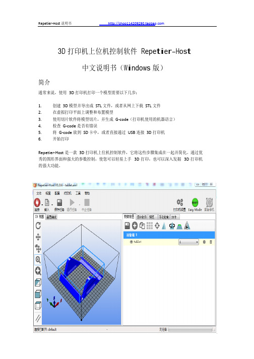
运行Repetier-Host软件,主界面如下图工具栏视图区功能区图 6 Repetier-Host主界面Repetier-Host软件主界面包括菜单栏,工具栏,视图区和功能区。
工具栏主要用于连接打印机,对打印机进行设置。
视图区主要用来查看模型、G-Code文件、观察温度变化曲线,另外包含一些查看视角快捷按钮。
功能区是该软件的核心区域,包含5个功能块:物体放置、切片软件、预览、手动控制和SD卡。
【打印虎】RepRap Prusa i3 3D打印机Melzi专用LCD控制器使用指南
【打印虎】RepRap Prusa i3 3D打印机Melzi专用LCD 控制器使用指南对于Prusa i3 3D打印机的玩家来说,有一个比较常见的问题,就是3D打印机本身没有可供用户交互的界面,必须通过USB连接,使用PC上的Repetier-host或同类的3D打印机控制软件,才能对3D打印机进行有效的控制。
这对于起步阶段的玩家,打印一些小玩意是没什么问题的。
但是,当你需要打印高精度、大尺寸的3D打印作品时,问题就来了。
不论是提高精度,还是加大3D打印对象的尺寸,都意味着打印时间的大幅增加。
这样你的PC机就必须长时间开机。
如果你用的是笔记本电脑,你的电脑也不能移动了,要一直保持USB的连接状态。
而且,万一因为USB线的质量不佳导致传输出现问题(对于大型作品,在长达几十个小时的打印时间里,还是很可能出现的),你的作品就会功亏一篑,令人抓狂。
想解决这样的问题也不难,只要给3D打印机增加一个LCD液晶显示屏模块,就可以解决在3D打印机上直接人机交互的问题。
再配合上SD卡,我们就不再需要使用USB连接,完全可以依靠3D打印机自身完成所有的工作。
同时,3D打印的稳定性也会上一个台阶。
市面上已经有一些这样的模块,不过打印虎针对Melzi主板做了一个更完善的方案:1. 可以与Melzi主板完美配合使用;2. 使用了大尺寸显示屏,同屏可以显示更多的信息;3. 基于Repetier-firmware 0.91固件,稳定可靠;4. 完整的、容易理解的全中文用户界面。
从以上几点可以看出,打印虎的Melzi LCD控制器方案还是有些特色的。
下面我们先来看看这个模块的外观,然后给大家详细讲解用户界面的使用方法:可以看出,这个模块的主体,是一块很大的LCD显示屏。
下面有几个按钮,可以用来操作。
模块侧面有一个小开关(图中被挡住了)用来控制LCD背光,允许用户在夜间使用时把蓝色灯光关闭。
在Melzi启动过程中,LCD上会显示出版权信息。
4打印机软件Repetier-Host中文说明书
3D 打印机上位机控制软件 Repetier-Host
中文说明书(Windows 版)
简介
通常来说,使用 3D 打印机打印一个模型需要以下几步:
1. 创建 3D 模型并导出成 STL 文件,或者从网上下载 STL 文件 2. 在虚拟打印平面上调整和布置模型 3. 使用切片软件将模型切片,并生成 G-code(打印机使用的机器语言) 4. 检查 G-code 是否有错误 5. 将 G-code 放到 SD 卡中,或者直接通过 USB 连接 3D 打印机 6. 开始打印
调整方向和大小 .............................................................................................................................. 8 复制对象 ..........................................................................................................................................9 选择和移动对象 .............................................................................................................................. 9 调整完后 .............................................................................................................................................. 9
GEEETECH GT2560用户手册说明书
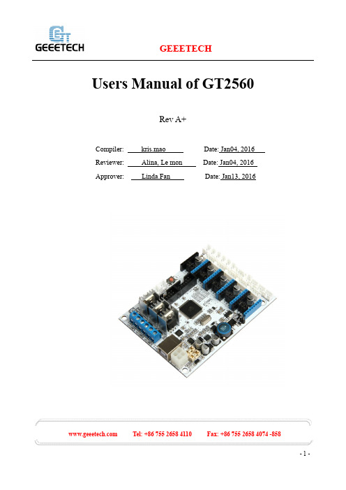
Users Manual of GT2560Rev A+Compiler: kris.mao Date: Jan04, 2016Reviewer: Alina, Le mon Date: Jan04, 2016Approver: Linda.Fan Date: Jan13, 2016 Tel: +86 755 2658 4110 Fax: +86 755 2658 4074 -858ContentsCopyright Declaration (3)Technical Support (3)1 Introduction (4)1.1Overview and Hardware Resources (6)1.2 Software Resources (8)1.3Source (8)2 Interfaces (9)2.1 Interface Layout (9)2.2 Interface specifications (9)2.3 subdivision of stepper motor (10)2.4 Fan connection (11)3 Development Environment setting (13)3.1 Interface Connecting and Setting (13)3.2 Software setting (14)3.3 File Burning (18)4Get Started (21)5 FAQ (25) Tel: +86 755 2658 4110 Fax: +86 755 2658 4074 -858Copyright DeclarationThe copyright of this specification belongs to the Shenzhen GETECH CO., LTD. (hereinafter referred to as the "Geeetech"), and all rights reserved. No part of this specification should be reproduced or extracted in any forms or means without the prior written consent of Geeetech by any company and individuals.Technical SupportIf you are interested in the technology of 3 D printing, flight control and U-home, welcome to Geeetech, we have series of made-up products, main boards, modules and a variety of peripherals for you. Or if you are looking for relevant information or technical support, please login our forum where you can find anything you want about open source. To know more about our new products, please visit , we will serve you wholeheartedly. Tel: +86 755 2658 4110 Fax: +86 755 2658 4074 -8581 IntroductionGT2560 is a compact board that is integrated with the mighty function of the Arduino Mega25 60+Ultimaker and Arduino Mega2560+ramps 1.4 on respect of both software and hardware and has more premium features: the streamlined interfaces effectively avoid the unnecessary troubles, well-regulated compaction of components highly integrated saves more space and easier to be mounted o n most applications.5 stepper motors, swappable driving modules, mighty ATmega2560 processor with 256k mem ory, 16MHz operating frequency, high-performance USB serial converter CH340C, all these make t he GT2560 an ideal option for a 3D printer control board. What’s more, GT2560 can run over 12V t o 24V which gives higher torque and higher rotation rate.Features:1.Integrated with the mighty function of the Arduino Mega2560+Ultimaker and Arduino Mega2560+ramps 1.4 kit, The GT2560 can not only take full place the them on respect of both software and hardware, but also features compact size, more convenient connection, and more stable.2. Adopt ATmega2560 as the main control chip, coupled with the high-performance USB serial converter CH340C.3. The power pack: operating voltage is 12V-24V; double power supply design feeds for heatbed and logical part separately. The current is 15A for heatbed and 10A for other parts.4. The main circuit adopts SMD fuse tube, the diode added to the power port can provide reverse protection to the whole circuit, in addition, the 5V USB is USB port protected with 500mA Recoverable fuse.5.3 12v fan output and one PWM output for LED or other lighting equipment. Tel: +86 755 2658 4110 Fax: +86 755 2658 4074 -8586. 3 55Amp MOSFET (with LED indicator, the actual output is restricted by the PCB board and the connector), all 3 MOSFET are equipped with heat sink to ensure sufficient heat dissipation and stable operation.7. Support 5 A4988 stepper drivers (3 for X/Y/Z axis, and 2 for extruders); the subdivision of stepper motor can be setup by dial switch, eliminating jumper caps, easier to operate.8. 3 temperature sensor input (100k thermistor is recommended)9. Extended LCD and SD card interface support both LCD2004 and LCD 12864, with which you can print without your PC.10. The firmware is the prevalent Marlin, which is known for stability, usability, and high-performance.Update log:1. A 3-pin straight pin is added to connect with 3D touch auto leveling sensor.2. The USB connector will not provide 5V for the board, if you need to refresh the firmware, please provide external power supply.3. The power port has been changed from hollow to solid one to provide higher current-carrying capability.4. The three heater connecter has been changed into blue ones: 2-pin RC3015.0mm 15A Tel: +86 755 2658 4110 Fax: +86 755 2658 4074 -8581.1Overview and Hardware Resources Tel: +86 755 2658 4110 Fax: +86 755 2658 4074 -858 Tel: +86 755 2658 4110 Fax: +86 755 2658 4074 -8581-1(front and back images) Hardware resources 12V/24V 15A and 12V/24V 10A power supply 1 power port for heatbed and 2 for extruder 5 stepper motor input, (3 for X/Y/Z axis, and 2 for extruders) Extended LCD & SD card interface6 endstop input(X-MIN ,Y-MIN ,Z-MIN 和X-MAX ,Y-MAX ,Z-MAX) 3 input for thermistor (TEMP1, TEMP2 and TEMP3)3 input for12V cooling fan1 PWM outputDimension: 109mm*80mm*22mmweight:87 g* The specifications of Pin connectors:Motor: XH (2.54mm-4pin)Fan: PH (2.00mm-3pin)Endstop and thermistor: XH (2.54mm-2pin)1.2 Software ResourcesCompiling environment: Arduino IDEFirmware: Marlin1.3SourceArduino IDE:/wiki/index.php/DownloadMarlin:/wiki/images/3/39/Marlin-Marlin_v1.zipRepetier-Host:/wiki/images/3/36/SetupRepetierHost_1_00.zip Tel: +86 755 2658 4110 Fax: +86 755 2658 4074 -8582 Interfaces2.1 Interface Layout2-12.2 Interface specifications1.DC IN:12V-24V 15A and 12V-24V 10A2. HOT_BED: heat bed3. HEATER1: power supply for extruder 14. HEATER2: power supply for extruder 2 Tel: +86 755 2658 4110 Fax: +86 755 2658 4074 -8585.LCD ENCODER:LCD panel6. SD Card7. X_MIN/X_MAX/Y_MIN /Y_MAX /Z_MIN /Z_MAX: 6 end stop input, XH2.54-2Pin8. TEMP1: temperature sensor for extruder 1, XH2.54-2Pin9. TEMP2: temperature sensor for extruder 2, XH2.54-2Pin10. TEMP3: temperature sensor for heatbed, XH2.54-2Pin11. X,Y,Z:Stepper motors for X, Y, Z axis, XH2.54-4Pin12. EXT1, EXT2(A):Stepper motors for extruder 1 and extruder 2, XH2.54-4Pin13. FAN1,FAN2,FAN3:3 12V cooling fans, PH2.0-3Pin14.1 PWM: PWM output for cooling fan, FAN: PH2.0-3Pin2.3 subdivision of stepper motorUse jumper caps to subdivide stepper motor. When jumper cap is plugged, it is ON.2-21. Subdivision on the base of A4988 stepper driving module: Tel: +86 755 2658 4110 Fax: +86 755 2658 4074 -8582. Subdivision on the base of Drv8825 stepper driving module:2.4 Fan connectionAs default, no matter the power supply is 12V or 24V; you need to connect the 12V fan as ther e is a separate chip that can provide power supply for the fan. If you choose the 24V fan and 24V po wer supply, you need to connect the JP2 with jumper cap. As shown in the picture. Tel: +86 755 2658 4110 Fax: +86 755 2658 4074 -858Note: this function is only available for versions after REV A. Tel: +86 755 2658 4110 Fax: +86 755 2658 4074 -8583 Development Environment setting3.1 Interface Connecting and Setting3-1Note:Pay attention to the Plus-n-Minus of the power connector, reverse connection can cause irrevocably damages. Tel: +86 755 2658 4110 Fax: +86 755 2658 4074 -858A4988 should also be connected to the right port, mismatches and revered directions can cause damage to the main board. You can the correct connections are as follow:3-2If you are using DRV8825 instead of A4988, The correct connections are as follow:3-33.You are suggested to connect all the Periphery modules before testing.3.2 Software settingCH340C Driving Installation:Connect the printer to computer with USB cable. The motherboard driver installer will automatically appear. Please check the following steps.1.When you connect your printer to computer with a USB cable. The following dialog box will Tel: +86 755 2658 4110 Fax: +86 755 2658 4074 -858appear.2.In the Arduino IDE when the CH340C is connected you will see a COM Port in [Devicemanager]. The COM number for your device may vary depending on your system.3.After successful installation, a pop-up box will appear as follows. Tel: +86 755 2658 4110 Fax: +86 755 2658 4074 -858 Tel: +86 755 2658 4110 Fax: +86 755 2658 4074 -858Note: If the driver fails to install automatically, you can finish the installation job manually. Here are the detailed steps.1. Download CH340C here, which is the driver of GT2560:/download/CH341SER_EXE.html (Windows OS) /download/CH341SER_MAC_ZIP.html (MAC OS) /download/CH341SER_LINUX_ZIP.html (LINUX OS) 2. Unzip the file.3. Run the installer which you unzipped.4. In the Arduino IDE when the CH340C is connected you will see a COM Port in [Devicemanager]. The COM number for your device may vary depending on your system. Tel: +86 755 2658 4110 Fax: +86 755 2658 4074 -8585. Click [Install] to continue.6. After successful installation, a pop-up box will appear. Tel: +86 755 2658 4110 Fax: +86 755 2658 4074 -8583.3 File BurningWindows users need install driver before uploading. The board: Tools > Board > Arduino Mega 2560 or Mega ADK, as shown below.3-10Configuring serial interface: Tools > Serial Port > the corresponding COM Port of GT2560 usuallythe last one. As shown below3-11Load in the file you need to burn, Click the “check ()” button to check if it is right and then click the “” button to upload firmware, as shown below. Tel: +86 755 2658 4110 Fax: +86 755 2658 4074 -858 Tel: +86 755 2658 4110 Fax: +86 755 2658 4074 -858图3-123-13Upon uploading, the LED indicator corresponding to the TX , RX and L on the GT2560 will blink, if they stop blinking, it means the file has been uploaded successfully. Tel: +86 755 2658 4110 Fax: +86 755 2658 4074 -8583-14After uploading, you can go on to the next step. If you cannot upload, check the dialog box below to identify the problem and solve it. The common mistakes are the wrong select of type of board or serial port etc.4 Get StartedGT2560 is the CPU of a 3D printer, manipulating the whole process of printing. GT2560 can’t be put in use directly without uploading firmware. 1. Firmware uploading- marlin. 2. Setting parameters of the firmwareThe parameters that need setting are as below, for those not mentioned just leave them as default.#define BAUDRATE 250000This parameter is for the baud rate of serial port. Note: a successful communication can be realizedonly when the Baud rate of upper computer is identical with that of Firmware. The Baud rate is not set in random. The common Baud rate are: 2400,9600,19200,38400,57600,115200,250000. The last three are frequently used for 3D Printer.#define MOTHERBOARD 7This parameter is set for board type. 3D Printer has many types of main board, and the settings of IOs are different, therefore, the parameter has to correspond to the type of your b oard, or it can’t operate normally. The parameter of GT2560 should be 7(single- nozzle). For other board, you can refer to the annotation on the board.#define TEMP_SENSOR_0 1#define TEMP_SENSOR_BED 1The two parameters are set for the type of temperature sensor respectively. They are the critical parameter to check if the sensor read temperature correctly. The printer can’t operate normally, even has potential risk (damage the device and even worse). You must modify depending on the temperature sensor you use.#define EXTRUDE_MINTEMP 170This parameter is set to avoid potential risks when the extruder operates before reaching the rated temperature. If you use other 3D Printer, such as printer to make Chocolates, 45℃is appropriate, so that the parameter configured to a lower value(such as 40℃).const bool X_ENDSTOPS_INVERTING = true; Tel: +86 755 2658 4110 Fax: +86 755 2658 4074 -858const bool Y_ENDSTOPS_INVERTING = true;const bool Z_ENDSTOPS_INVERTING = true.The three parameters are set for the end stops of three axes. If the configuration is true, the end stop outputs 1 in default condition, and outputs 0 when triggered. That is to say, mechanical end stop should connect to the NO (normally open) contactor. If it is connected to the NC (normally closed), true should be changed to false.#define INVERT_X_DIR false#define INVERT_Y_DIR trueMistakes are often made in the above two parameters. The parameters are different for different machinery. In principle, the origin should be at lower-left corner of the print platform (origin: [0, 0]), or at up-right corner (origin: [max, max]). Only in this way will the printing be correct, otherwise, the printing is the mirror image of one axis which is not what expected.#define X_HOME_DIR -1#define Y_HOME_DIR -1#define Z_HOME_DIR -1If the position of the origin is the minimum, the parameter is -1; if it is the maximum, the parameter is 1.#define X_MAX_POS 205#define X_MIN_POS 0#define Y_MAX_POS 205 Tel: +86 755 2658 4110 Fax: +86 755 2658 4074 -858#define Y_MIN_POS 0#define Z_MAX_POS 200#define Z_MIN_POS 0These parameters are crucial to the printing size. Fill in parameters by reference to the coordinate graphs. It is important to note that the origin is not the printing center and the real printing center usually lies at [(x.max - x.min)/2, (y.max -y.min/2)]. The coordinate of central will be used in the slice tool. The printing center’s coordinate must correspond to the parameter configuration, or it will print to the outside of the platform.#define HOMING_FEEDRATE {50*60, 50*60, 4*60, 0}The parameter means the homing speeds (mm/min). This parameter can be set as default if you use the x-axis and y-axis adopt synchronous belt drive and z-axis adopts screw drive.#define DEFAULT_AXIS_STEPS_PER_UNIT {85.3333, 85.3333, 2560, 158.8308}These parameters are crucial to the printing size. These parameters indicate the pulse the axis need when operating 1mm. they are corresponding to x, y, z axis and extruder respectively. In most cases these figure should be calculated by yourself, you can refer to:http://calculator.josefprusa.cz/#steppers.So far, the commonest parameters have been configured and the printer can work now. In addition, if the 2004 LCD needs verifying, you should delete the “//” from “//#define REPRAP_DISCOUNT_SMART_CONTROLLER” to ensure the normal working. Tel: +86 755 2658 4110 Fax: +86 755 2658 4074 -8585 FAQ1. How many extruders can GT2560 support?At most 2 extruders, GT2560 supports 5 A4988 stepper motor drivers, they are X/Y/Z axis and 2 extruders.2. What is the power required?You need to use the 12V-24V power supply, and if you are using the single extruder one, the total power is no less than 200W, if you are using the dual extruder one, the total power is no less than 2 40W.3. The stepper motor on for the extruder doesn’t turn?By default in the firmware, only when the temperature of the extruder reaches 170°C can the moto r turn. Tel: +86 755 2658 4110 Fax: +86 755 2658 4074 -858。
iSense安装说明书

PC requirements Processor RAM Screen resolution Hard disk Operating system
Interface
iCore 4 GB 1280 1024 or higher 250 MB available space MS-Windows 7 / 8 / 8.1 (at least XP SP 3 or later) USB and / or Bluetooth (depending on the accessory)
The firmware of iLink-RS 485 and iLink-RS 485 VP has to be updated for use with the new iSense.
Please read the iSense Manual on the CD for details on iSense instaG, Process Analytics Im Hackacker15, CH-8902 Urdorf, Switzerland Tel. +41 44 729 62 11. Fax +41 44 729 62 11
/ pro
iSense Installation Note
Subject to technical changes. © Mettler-Toledo AG. 06 / 14 Printed in Switzerland. 30 138 236
Mettler-Toledo AG, Process Analytics Im Hackacker15, CH-8902 Urdorf, Switzerland Tel. +41 44 729 62 11. Fax +41 44 729 62 11
4打印机软件Repetier-Host中文说明书

4打印机软件Repetier-Host中文说明书4打印机软件Repetier-Host中文说明书1、简介Repetier-Host是一款用于控制3D打印机的软件。
本文档将详细介绍该软件的安装、设置和使用方法。
2、系统要求在开始使用Repetier-Host之前,请确保您的计算机系统符合以下要求:- 操作系统:Windows 7及以上版本、Mac OS X 10.8及以上版本、Linux- 处理器:双核处理器及以上- 内存.4GB及以上- 硬盘空间:至少100MB可用空间3、安装Repetier-Host1) Repetier-Host安装程序。
2) 运行安装程序,并按照提示完成安装过程。
3) 安装完成后,启动Repetier-Host。
4、连接3D打印机1) 将3D打印机通过USB线缆连接到计算机。
2) 打开Repetier-Host,在主界面“连接”按钮。
3) 在弹出的对话框中选择正确的串口和波特率,“连接”按钮。
5、配置打印机参数1) 在主界面的左侧菜单栏中“配置”。
2) 在“机械”选项卡中,设置打印机的相关参数,如打印范围、步进电机细分等。
3) 在“温度”选项卡中,设置打印头和热床的温度。
4) 在“连接”选项卡中,可以设置打印机连接方式和通信参数。
5) 在“外观”选项卡中,可以设置软件的界面显示方式。
6) 完成配置后,“保存”按钮。
6、打印模型1) 在主界面的左下方“打开G代码”按钮,选择要打印的模型文件。
2) 在打开的模型文件中,通过鼠标操作调整模型的位置和大小。
3) “切片和预览”按钮,选择适当的切片参数,并G代码。
4) 在预览界面中,可以查看模型的打印轨迹和预估打印时间。
5) “开始打印”按钮,开始打印模型。
7、监控打印过程1) 在打印过程中,可以通过主界面的右侧监控窗口实时查看打印进度和温度信息。
2) 如果发现打印异常,可以通过右侧菜单栏中的“暂停”按钮暂停打印,并进行必要的调整。
- 1、下载文档前请自行甄别文档内容的完整性,平台不提供额外的编辑、内容补充、找答案等附加服务。
- 2、"仅部分预览"的文档,不可在线预览部分如存在完整性等问题,可反馈申请退款(可完整预览的文档不适用该条件!)。
- 3、如文档侵犯您的权益,请联系客服反馈,我们会尽快为您处理(人工客服工作时间:9:00-18:30)。
Repetier-Host文档安装安装条件在你开始安装本程序之前,你应该检查你的电脑是否符合安装要求。
一般来说现在使用的电脑安装不会存在任何问题。
如果你的电脑旧到仍在运行Windows XP 你可能会有困难。
这款软件将在之后开始支持Windows Xp和Linux(现在已经支持)。
如果你有一台Maxintosh(苹果1984年前后出产的电脑),你可以在此网站的Repetier-Host Mac 查找你所需要的信息。
如果你在Linux下安装,安装所需要的不过是.NET frame 4.0或者安装一个最新的Mono。
另外你的显卡需要支持OpenGL.如果你想获得一个更好的反馈效果,显示卡最好支持OpenGL1.5或者更高版本。
低于此版本你可能在图形处理的速度和图形的视觉效果上给你带来不佳的体验。
下载软件在下载页面搞到并下载适合你操作系统的最新版本Windows环境下的安装Windows版本的软件包中包含一个安装设置文件。
在下载完毕后直接点击安装设置文件工作就完成了。
配置文件中已经包含了Slice3r和Skeinforge来切片,python 和pypy,这些都需要运行SkeinforgeLinux环境下的安装Linux的安装文件是一个gzipped压缩的压缩包。
把它移动到你想放置的位置解压出里面的文件然后运行下面的脚本:tar -xzf repetierHostLinux_1_03.tgzcd RepetierHostsh configureFirst.sh在这之后,你应该在/usr/bin里将Repetier-Host 的安装文件链接进去,这样你就可以直接通过repetierHost命令来运行该程序。
确保你已经安装了所需要的Mono 库文件。
如果你不确定,可以安装Mono develop,里面包含有所有的程序运行所依赖的库文件。
有个一个绝大多数Linux发行版都会存在的问题就是,普通用户权限不能进行一些操作。
你需要把你的用户放进合适的组中,例如,在Debian中你可以这样调用:usermod -a -G dialout yourUserName来把你的用户放进dialout用户组中。
配置文件开始在运行开始的时候可能会弹出一个对话框来询问你,工作区域的路径是哪.在最新的Windows版本跳过了这一步,因为配置安装文件已经为你自动地创建了一个工作路径。
你可以设置任何路径,但是一般来说使用一个和安装目录分开的路径会好一些。
(you can select any directory, where you have write privileges, but it is advised to use a separate directory for this purpose.)工作区域的路径就是软件存放临时stl文件,切片结果,如果允许生成日志文件,也会将其存放在该路径中.配置你的打印机安装完成之后的下一步就应该是通过软件配置你的打印机,以便于你的软件可以连接你的电脑和打印机.在开始之前请确保你的打印机和电脑相连并且可以使用.一些打印机需要特殊的驱动程序来连接设备,所以确保这个设备的驱动程序也已经被安装.如果你已经升级了打印机的固件,那么该驱动程序早就被安装了.在菜单栏中找到”配置(Config)”->”打印机设置(Printer Setting )”或者点击按钮,你将看到类似于下面的窗口.在该窗口的顶部可以看到一个可以下拉的按钮,对应栏显示的是当前被软件选中的默认打印机.在开始的时候你只能选择一台默认的打印机.如果你想创建一个新的打印机,你需要更改打印机的名字,之后点击”应用(Apply)”按钮.新创建的打印机将会沿用最近被选中打印机的设置参数.在顶部下拉按钮下面,你会看到一个有4个可切换的窗口,他们中保存着打印机配置的绝大部分信息.除此之外,每一个配置都会存储有开始/结束/暂停/终止和5个用户定义的脚本.这些可以在个该-code编辑器中更改,这些内容将在下面一章提到.在第一个可切换的窗口(“Printer”)中,你可以设置怎么连接你的打印机.在”端口(Port)”中可以选择你打印机连接的端口.在开放的窗口中,所有可用的端口都自动被扫描并加载到列表中.如果你连接打印机时软件已经运行,可以点击”刷新端口(refresh Ports)”来检测新的端口.请选择正确的端口.之后选择传进固件的带宽速率(baud rate).停止位(stop bits)和奇偶校验(parity)的对于99.9%的打印机都使用,所以不要设置这些参数.传输协议决定软件(host)将如何和打印机进行通信.所有被支持的固件都在ASCII 模式下工作.Repetier-Firmware也支持二进制格式.二进制通信的优点如下所示:1.减少传输数据大小.采用二进制传输可以将普通的数据大小减少50%2.更强的错误校验能力3.固件解析数据所花的计算时间更少..你可以选择”自动检测(Auto detect)”,他将自动在检测到Repetier-Firmware后自动切换到二进制格式.对于其他固件,ASCLL码形式的交流也会被使用.接下来我们要讨论的是,怎么样将数据发送给固件.它的工作形式其实就像打乒乓球一样。
软件向固件发送一个命令并等待其返回一个ok信号。
这就造成了一个延时,也可能导致当你有一些小的移动时缓冲区为空的情况。
为了改进这种状况,你可以向缓冲器发送多个命令。
你的打印机有个输入缓冲区域。
只要你发送的命令没有超过缓冲器的大小。
所以你使“乒乓球”模式不可用后,软件将会发送“接收cache大小”的位数,在等待打印机返回ok之前,告诉它该命令已经被执行,如果你不切丁打印机缓冲器的大小,可以选择63,这个设置可以在所有的打印机上工作。
用Arduino1.0及更低版本的固件甚至允许你选择127位。
第二个可切换窗口定义了你需要的重要行为。
当你在使用人工控制挤出器移动的时候,移动喂食率(travel feed rate)和(Z-轴喂食率)。
温度设置在人工控制窗口中对应的位置,你可以在任何时候改变他们。
当你把挤出器打开的时候,你一定想要知道它的温度。
这些可以发送M105命令给打印机来完成。
如果你不想每隔一段时间就来检测这个选项。
你可以选择让软件多久检查一次温度。
其实每3秒检查一次是个不错的选择。
每一个请求你在你的日志中得到2项。
主机将显示读取温度在底部的状态栏,从日志删除这些消息使它更具可读性。
停驻位置(Park Position)是你最想让你的挤压头所在的地方,在人工控制的状态下你有一个按钮来讲挤压头移动到停驻位置。
你也可以告软件让其打印结束后,运行到这个位置。
下一个单选按钮定义打印机应该做什么,当一次打印结束并且SD卡可用时。
如果SD卡不可用,corresponding tab将不会被显示。
通过设置“添加到计算机,打印时间(Add to comp .printing time)”,将会告诉打印机怎么样修正已经被计算好的打印时间。
当软件从来自g-code的代码来计算时间时,它总是假设每一步都是按照喂给速率要求(feed rate)来的。
如果你打印的速度很慢,这将会非常精确,但是它忽略了加热挤压头/床的时间。
如果你使用快速打印模式,固件需要生成一个加速或者减速日志,这就增加了打印时间。
在你打印过一些东西之后,你会发现真是打印时间和计算打印时间是不相同的,你也会慢慢弄清楚实际你需要在计算的时间之外等多少时间。
不要期望你的经验能够适合每一次打印,打印的结构不同,打印的时间也会有所不同。
在最后,你可以在人工控制的状态下改变移动方向。
在名为“挤压头控制(Extruder)”的小窗口,你可以定义挤压头的数量,最大值,温度等在人工控制下可以改变的参数。
每秒最大量(The max volume per second)定义了挤压头每秒可以融化的最大数值,但是为mm³.对于每一个挤压头,你都可以定义一个名字,一个喷嘴直径(直径值只会被用于CuraEngine),一个温度补偿量,该补偿量会被叠加禁熔丝温度(filament temperture),如果这个挤压头被选中了(这也只在CuraEngine下发生),一个颜色设置,该颜色设置将会用于预览,和x轴,Y轴偏移补偿量,这些可以用来调节多挤压头的挤压头位置。
一些固件例如Repetier-firmware将会自动的修正偏移补偿量,如果是这样,请将其补偿量设置为0.“打印机外形(Printer Shape)”设置窗口可以定义你的打印机形状,或者可以更确切的说,是你用来打印的区域。
如果你的模型能在打印床上打印,软件将会通过这来限制打印机的移动并检查。
你也可以定义打印机在哪个位置(x和y)然后停止。
垃圾区域(Dump area)是在你打印床上的一个长方形洞,这个地方你可以将为溶熔解的熔丝扔在那,大多数原始的孟德尔打印机(Mendel)都有这个选项。
如果没有垃圾区域,请忽略该选项。
最后一个可切换小窗口是为高级设置准备的,你可能永远都用不上它。
当前版本它只包含一个目前它只包含一个后处理过滤器(Currently it only contains a post process filter)。
另外,当切片完成以后,你可以通过编写g-code让打印机进行额外的工作(你可以在打印开始之前通过g-code修改该项目)。
额外的工作必须将g-code以#outparame的形式保存在文件夹里。
单位设置软件内部使用毫米为单位。
不幸的是STL和OBJ形式的文件不支持比例缩放。
因此你需要为你所创造的模型选择一个单位。
通过这种方式软件可以正确的将你所选的单位转化为毫米。