HVAC系统调试大纲
美国标准(American Standard)HVAC系统设计指南:2006年版说明书

•providing insights for today’s hvac system designer© 2006 American StandardAll rights reserved●1volume 35–4energy-saving control strategies forRooftop VAV SystemsRooftop variable-air-volume (VAV)systems are used to provide comfort in a wide range of building types and climates. This system consists of a packaged rooftop air conditioner that serves several individually-controlled zones. Each zone has a VAV terminal unit that is controlled by a temperature sensor in the zone.This EN discusses HVAC systemcontrol strategies that can be used to save energy in rooftop VAV systems.Optimal Start/Stop. In somebuildings, a simple time clock or time-of-day schedule is used to start and stop the HVAC system. During hours when the building is expected to be unoccupied, the system is shut off and the temperature is allowed to drift away from the occupied setpoint. The time at which the system starts again in the morning is typically set to ensure that the indoor temperature reaches the desired occupied setpoint prior to occupancy on either the coldest or warmest morning of the year. As a result, for most days, the system starts much earlier than needed. In turn, this increases the number of operating hours and system energy use.An alternative approach is a strategy called optimal start . This strategy utilizes a building automation system (BAS) to determine the length of time required to bring each zone from current temperature to the occupied setpoint temperature. The system waits as long as possible before starting, so that the temperature in each zone reaches occupied setpoint just in time for occupancy (Figure 1). This optimal starting time is determined using the differencebetween actual zone temperature and occupied setpoint. It compares this difference with the historicalperformance of how quickly the zone has been able to warm up or cool down.The optimal start strategy reduces the number of system operating hours and saves energy by avoiding the need to maintain the indoor temperature at occupied setpoint even though the building is unoccupied.A related strategy is optimal stop . As mentioned earlier, at the end of the occupied period, the system is shut off and the temperature is allowed to drift away from occupied setpoint.However, the building occupants may not mind if the indoor temperature drifts just a few degrees before they leave for the day.Optimal stop uses the BAS to determine how early heating and cooling can be shut off for each zone, so that the indoor temperature drifts only a few degrees from occupiedsetpoint (Figure 1). In this case, only cooling and heating are shut off; the supply fan continues to operate and the outdoor-air damper remains open to continue ventilating the building.The optimal stop strategy also reduces the number of system operating hours, saving energy by allowing indoor temperatures to drift early.Fan-Pressure Optimization. As cooling loads change, the VAV terminals modulate to vary airflow supplied to the zones. This causes the pressure inside the supply ductwork to change. In many systems, a pressure sensor is located approximately two-thirds of the distance down the main supply duct. The rooftop unit varies the capacity of the supply fan to maintain the static pressure in this location at a constant setpoint. With this approach, however, the system usually generates more static pressure at part load than necessary.When communicating controllers are used on the VAV terminals, it is possible to optimize this static-pressure control function to minimize duct pressure, and save fan energy. Each VAV unit controller knows theoccupied setpoint temperature mid 6 AM noon 6 PM midFigure 1. Optimal start and optimal stop2●Trane Engineers Newsletter volume 35–4providing insights for today’s HVAC system designercurrent position of its air-modulation damper. The BAS continually pollsthese individual controllers, looking for the VAV terminal with the most-open damper (Figure 2). The setpoint for the supply fan is then reset to provide just enough pressure so that at least one damper is nearly wide open. This results in the supply fan generating only enough static pressure to push the required quantity of air through this "critical" VAV terminal unit.This control strategy, sometimes called fan-pressure optimization, has several benefits:•Reduced supply fan energy use . At part-load conditions, the supply fan is able to operate at a lower static pressure and consume less energy (Figure 3).•Lower sound levels . The supply fan does not generate as much static pressure and will typically generate less noise. In addition, with lower pressures in the supply duct, the dampers in the VAV terminals will be more open, resulting in less regenerated noise.•Reduced risk of fan surge . Byallowing the fan to operate at a lower pressure when delivering reduced airflow, the fan operating point is kept further away from the surge region (Figure 3).•Flexibility of sensor location. Since this strategy uses the position of VAV dampers to reset the pressure setpoint, the static-pressure sensor can be located anywhere in the supply duct. It can even be located at the discharge of the fan, allowingit to be installed inside the rooftop unit and tested at the factory. In this location, it can also serve as the duct high-pressure sensor, protecting the ductwork from damage in the event of a fire damper closing.Supply-Air-T emperature Reset . In a VAV system, it is tempting to raise the supply-air (SA) temperature at part-load conditions to save compressor and/or reheat energy. Increasing the supply-air temperature reduces compressor energy because it allows thecompressor to operate at a warmer suction temperature. Thecorresponding higher suction pressure reduces the compressor lift, reducing the power required.In addition, supply-air-temperature reset makes an airside economizer more beneficial. When the outdoor air is cooler than the SA temperature setpoint, the compressors are shut off, and the outdoor- and return-air dampers modulate to deliver the desired supply-air temperature. A warmer SA temperature setpointallows the compressors to be shut off sooner and increases the number of hours when the economizer is able to provide all the necessary cooling.For zones with very low cooling loads, when the supply airflow has been reduced to the minimum setting of the VAV terminal, raising the supply-air temperature also decreases the use of reheat at the zone level.However, because the supply air is warmer, zones that require cooling will need more air to satisfy the cooling load. This increases supply fan energy. Finally, in non-arid climates, warmer supply air means less dehumidification at the coil and higher humidity levels in the zones. If dehumidification is a concern, use caution when implementing this strategy.Supply-air-temperature reset should be implemented so that it minimizes overall system energy use. This requires considering the trade-off between compressor, reheat, and fanairflows t a t i c p r e s s u r eFigure 3. Benefits of fan-pressure optimizationFigure 2. Fan-pressure optimizationproviding insights for today’s HVAC system designerTrane Engineers Newsletter volume 35–4●3energy, as well as the impact on space humidity levels. Table 1 contains some general guidance to determine when this strategy might provide the most benefit.These competing issues are often best balanced by first reducing supply airflow, taking advantage of the significant energy savings fromunloading the fan. Once fan airflow has been reduced, raise the supply-airtemperature to minimize reheat energy and enhance the benefit of the airside economizer. While one could dream up numerous control schemes, the simplest approach is probably most common. Figure 4 shows an example of a supply-air-temperature reset strategy based on the changing outdoor dry-bulb temperature. When the outdoor temperature is warmer than 70°F , no reset takes place and the SA temperature setpoint remains at the design value of 55°F . When it is this warm outside, theoutdoor air provides little or no cooling benefit for economizing. The cooling load in most zones is likely highenough that reheat is not required to prevent overcooling. In addition, the colder (and drier) supply air allows the system to provide sufficiently dry air to the zones, improving part-load dehumidification.When the outdoor temperature is between 60°F and 70°F , the SAtemperature setpoint is reset at a 2-to-1 ratio. That is, for every 2°F change in outdoor temperature, the setpoint is reset 1°F . In this range, supply-air-temperature reset enhances the benefit provided by the economizerand it is likely that some zone-level reheat can be avoided.Finally, when the outdoor temperature is colder than 60°F , no further reset occurs, and the SA temperature setpoint remains at 60°F . Limiting the amount of reset to 60°F allows the system to satisfy the cooling loads in interior zones without needing to substantially oversize VAV terminals and ductwork.Alternatively, some systems reset the SA temperature setpoint based on the temperature in the "critical" zone. This is the zone that is most nearly at risk of overcooling, which would require activating local reheat. A buildingautomation system (BAS) monitors the temperature in all zones, finding the critical zone that is closest to heating setpoint. The rooftop unit then resets the SA temperature setpoint to prevent this critical zone from needing to activate reheat.When considering using supply-air-temperature reset in a rooftop VAV system:•First analyze the system to determine if the savings in compressor and reheat energy will outweigh the increase in fan energy.•If higher space humidity levels are a concern, consider either disabling reset when it is humid outside, or providing one or more humiditysensors to override the reset function whenever humidity in the zone exceeds some maximum limit.•For interior zones with near-constant cooling loads during occupiedperiods, calculate design airflows for those zones based on the warmer, reset supply-air temperature (60°F in the example from Figure 4). While this may require larger VAV terminals and ductwork, it allows the use ofsupply-air-temperature reset duringSource: California Energy Commission, Advanced Variable Air Volume System Design Guide, 2003.T able 1. Supply-air-temperature resetFigure 4. Supply-air-temperature reset based on OA temperature5560655080757061605958575655S A t e m p e r a t u r e s e t p o i n t , °Foutdoor dry-bulb temperature, °Fcooler weather, while still providing the necessary cooling to thoseweather-independent, interiorzones.•Design the air distribution system for low pressure losses and use the fan-pressure optimization strategyto minimize the fan energy penalty that accompanies a warmer SAtemperature.Ventilation Optimization . In a typical VAV system, the rooftop unit delivers fresh outdoor air to several, individually-controlled zones. Demand-controlled ventilation (DCV) involves resetting intake airflow in response to variations in zone population. Whilecommonly implemented using carbon dioxide (CO2) sensors, occupancy sensors, or time-of-day (TOD) schedules can also be used.Ventilation reset involves resetting intake airflow based on variations in system ventilation efficiency.One approach to optimizing ventilation in a multiple-zone VAV system is to combine the various DCV strategies at the zone level (using each where it best fits) with ventilation reset at the system level.With this strategy, CO2 sensors are installed only in those zones that are densely occupied and experience widely varying patterns of occupancy. For the example building in Figure 5, CO2 sensors are installed only in the conference room and the lounge. These zones are the best candidates for CO2 sensors, and provide "the biggest bang for the buck." These sensors reset the ventilation requirement for their respective zones based on measured CO2.However, zones that are less densely occupied or have a population that varies only a little (such as private offices, open plan office spaces, or many classrooms) are probably better suited for occupancy sensors. In Figure 5, each of the private offices has an occupancy sensor to indicate when the occupant is present. Whenunoccupied, the controller lowers theventilation requirement for the zone.Occupancy sensors are relativelyinexpensive, do not need to becalibrated, and are already used inmany zones to control the lights.Finally, zones that are sparselyoccupied or have predictableoccupancy patterns may be bestcontrolled using a time-of-dayschedule. This schedule can eitherindicate when the zone will normallybe occupied vs. unoccupied, or can beused to vary the zone ventilationrequirement based on anticipatedpopulation.These various zone-level DCVstrategies can be used to reset theventilation requirement for theirrespective zones for any given hour.This zone-level control is then tiedtogether using ventilation reset at thesystem level (Figure 6).In addition to resetting the zoneventilation requirement, the controlleron each VAV terminal continuouslymonitors primary airflow beingdelivered to the zone. The BASFigure 5. Demand-controlled ventilation at the zone levelUnoccupied Humidity ControlA VAV system typically dehumidifieseffectively over a wide range of operatingconditions because it continues to delivercold, dry air at part-load conditions. Aslong as supply-air-temperature reset isused with caution, and reheat is availablefor those VAV terminals that have highminimum airflow settings or experiencevery low cooling loads, a VAV system willtypically provide supply air at a dew pointthat's low enough to prevent elevatedindoor humidity levels during occupiedperiods.However, controlling humidity levels isn'tonly a priority when the building isoccupied. When indoor humidity rises toohigh during unoccupied times, one optionis to turn on the rooftop unit anddehumidify recirculated air to 55°F or so.However, there is typically very littlesensible load in the zones during theseperiods, so delivering this cold air willresult in overcooling. Reheat coils in theVAV terminals, and possibly a boiler andhot water pumps, will need to beactivated.An energy-saving alternative is to equipthe rooftop unit with hot gas reheat. Whenafter-hours dehumidification is needed,the rooftop unit turns on and diverts hotrefrigerant vapor leaving the compressorthrough a refrigerant-to-air heatexchanger that is located in the airstream,following the evaporator coil. Sensibleheat is transferred from the hot refrigerantto reheat the dehumidified air leaving theevaporator.This strategy uses heat recovered fromthe refrigeration circuit to reheat centrally,and saves energy by avoiding the use ofnew energy to reheat remotely at the VAVterminals.4●Trane Engineers Newsletter volume 35–4providing insights for today’s HVAC system designerproviding insights for today’s HVAC system designerTrane Engineers Newsletter volume 35–4●5periodically gathers this data from all VAV terminals and solves theventilation reset equations (prescribed by ASHRAE Standard 62) to determine how much outdoor air must be brought in at the rooftop unit to satisfy all zones served. Finally, the BAS sends this outdoor airflow setpoint to the rooftop unit which modulates a flow-measuring outdoor-air damper to maintain this new setpoint.In a DDC/VAV system, this strategy is fairly easy to implement because the necessary real-time information is already available digitally. Combining DCV at the zone level with ventilation reset at the system level has the following benefits:•Assures that each zone is properly ventilated without requiring a CO 2 sensor in every zone . CO 2 sensors are used only in those zones in which they will bring the most benefit. This minimizes installed cost and avoids the periodic calibration and cleaning required to assure proper sensor operation. For the other zones,occupancy sensors and time-of-day schedules are used to reduce ventilation.•Enables documentation of actual ventilation system performance . The VAV controllers communicate the ventilation airflow for every zone to the BAS, even for those zones that do not have a CO 2 sensor. The BAS can be used to generate reports showingventilation airflow (cfm) in every zone for every hour.•Uses system-level ventilation reset equations that are explicitly defined in an industry-wide standard . Using equations from ASHRAE 62 improves the "defend-ability" of the control strategy.Summary. The impact of any energy-saving strategy on the operating cost of a specific building depends on climate, building usage, and utility costs. Building analysis tools (like TRACE™ 700) can be used to analyze these strategies and convert energy savings to operating cost dollars that can be used to make financial decisions.Figure 7 shows the potential energy savings of using these variousstrategies in an office building that has a typical rooftop VAV system. The optimized system uses the optimal start, supply-air-temperature reset, and ventilation optimization strategies discussed in this EN. In addition, the supply fan is controlled based on fan-pressure optimization, rather than on a constant setpoint in the ductwork.The optimized rooftop VAV system reduced the HVAC energy use by about 30% for the building in both Atlanta and Los Angeles, and by 33% in Minneapolis.There is a real potential to save energy in rooftop VAV systems throughoptimized system control strategies. This savings reduces operating costs for the building owner and can help in achieving points toward LEED ® certification.Article by John Murphy, applicationsengineer,Trane. Y ou can find this and previous issues of the Engineers Newsletter at /engineersnewsletter. To comment,***********************.Figure 6. Ventilation reset at the system levelFigure 7. Energy-saving potential of optimized controlMinneapolisLos AngelesAtlanta20406080100H V A Ce n e r g y c o n s u m p t i o n , % of b a s eoptimized system controlsbase systemT raneA business of American Standard CompaniesFor more information, contact your local Trane***********************************Trane believes the facts and suggestions presented here to be accurate. However, final design andapplication decisions are your responsibility. Trane disclaims any responsibility for actions taken onthe material presented.6●Trane Engineers Newsletter volume 35–4ADM-APN022-EN (October 2006)。
HVAC的施工、调试以及设计确认
HVAC的施工、调试以及设计确认今天继续说说空调系统的施工、调试以及设计确认。
洁净厂房与空调净化系统施工工艺及施工过程控制将直接影响系统运行稳定性,影响系统性能的优劣,而且绝大部分的影响在工程竣工后将不可更改。
结合工程管理和验证活动中的经验,洁净厂房与空调净化系统的施工过程中应重点关注以下内容,形成正式记录并存档。
1. 应保存各种部件的原始资料,包括材质证明以及其他合格证明材料。
1)壁板、顶板、门、窗、地面等洁净室主要部件相关资料2)风管、风阀、过滤器等主要部件的相关资料3)送风空调机组、排风空调机组等设备的相关资料4)洁净室内安装的各附属物相关资料,如洁净灯具、洁净电话等2. 保存各种施工及验收记录1)风管制作清洗记录2)风管漏风、漏光检测记录。
3)空调系统空吹记录。
4)高效过滤器安装记录。
5)其他记录。
6)保存各种设计及施工变更资料。
施工过程中出现的各类设计变更与施工变更应同样遵循项目变更控制的要求进行管理。
(点评:工程阶段的变更与空调系统交付后的变更管理起来还是有所不同的,工程变更相对来说会更加灵活一些,不过工程变更往往也是项目进度受影响或者成本增加的重要的因素,宁愿多花点儿时间在前期的设计阶段,而不要等到施工阶段再去变更)在系统调试或运行过程中,当某项参数有较大变化时,在非自控条件下可能会带来的影响。
例如,过滤器发生堵塞,使得房间风量、换气次数持续降低,对房间洁净度及微生物控制产生不利影响,同时洁净区内的自净时间也会延长;总风量降低后,虽然新风比可能没有较大变化,但新风量会随之锐减,进而影响系统整体静压差及温湿度控制。
(点评:指南上还有一张各参数的影响图,但并不是十分清楚,现在大多数的系统应该也是自控的了吧,所以就把这张图省略了)正是由于空调系统各参数之间的影响关系错综复杂,所以在调试过程中应全面统筹考虑,每一个参数的微小调整都可能会造成整个系统参数或大或小的变动,进而影响系统整体性能。
美国标准 HVAC 制冷制热系统设计指南说明书

•providing insights for today’s hvac system designer© 2006 American Standard All rights reserved●1volume 35–3maintaining a comfortable environment inPlaces of AssemblyDesigning comfort systems for places of assembly (auditoriums,gymnasiums, arenas, houses of worship) presents some vexingchallenges. Such facilities often have acoustical requirements that place limits on equipment location and air distribution design. Many places of assembly experience extremely diverse loads and occupancyschedules, complicating part-load system control. But perhaps thebiggest challenge is occupancy itself, and its impact on ventilation and humidity control. Design guidelines that are commonly applied incommercial office space mayget us into trouble here.A simple example can illustrate some of these issues: a school gymnasium during a band concert. As this is a good high school band, both the bleachers and the floor are full. Occupancy is at the fire marshal’s rated seatingcapacity. The 18,000 ft 2 gymnasium is designed for 1200 people, including use of the gym floor. A load calculation reveals the following space loads:Roof 69,600 Btu/hr Wall 43,000 Btu/hr Glass 10,500 Btu/hr Lights 122,900 Btu/hrPeople 300,000 Btu/hr (sensible)240,000 Btu/hr (latent)Totals546,000 Btu/hr (sensible)240,000 Btu/hr (latent)Occupancy a Major FactorPeople constitute a significant portion of the space sensible cooling load, over 50 percent. However, it is the impact on humidity that makes occupancy a difficult load to manage. The space sensible heat ratio for this example is only 0.69 (Figure 1).If the target space comfort condition is 75°F and 50 percent relative humidity (RH), and the air distribution system is designed for 55°F supply air, the required supply airflow is over 4 cfmper square foot of floor area -- a huge amount! How did that happen?Humidity ratio tells the story. Humidity ratio is grains of water vapor per pound of air. The humidity ratio at 75°F dry bulb and 50 percent RH, the desired space condition, is 64.7 grains of water vapor per pound of air. The 55°F supply air has a humidity ratio of 60.4 gr/lb. At these conditions, each pound of supply air we introduce into the space can remove 4.3 grains of water vapor. If each occupant contributes 200 Btu/hr to the latent load, 1200 people add 230 pounds of water vapor (1,610,000 grains) to the air in the gymnasium. If each pound of supply air can remove only 4.3 grains of water vapor, it will take 374,000 pounds of supply air per hour. This equates to approximately 83,000 cfm, or 4.6 cfm/ft 2. That's a lot of air!Figure 1. Design sensible and latent loadsHumidity is the Driver.In this example, 83,000 cfm is required to handle humidity, but only 18,000 cfm of this must be outdoor air for ventilation (assuming 15 cfm of OA per person*). With a space sensible cooling load of 546,000 Btu/hr and a supply-air temperature of 55°F; approximately 25,000 cfm is required to maintain the space temperature at 75°F. In this case, 72% of the supply air must be outdoor air. While this is a high fraction of outdoor air, it is manageable. Ventilation air is not the culprit.This 25,000 cfm of supply air equates to 1.4 cfm/ft2. This is a large, but manageable supply air quantity. But we still need 83,000 cfm of supply air to control humidity. How do we better equip the supply air to handle the high latent load associated with this many people? Obviously the supply air needs to be drier. The drier the supply air (the lower the dew point), the more water vapor it will remove from the space. What supply air dew point is required to handle the space latent load?*While many local codes may still require 15 cfm/ person for ventilation, the most recent version of ASHRAE Standard 62.1-2004 has revised the minimum required ventilation rates for places of assembly.Calculating Specific Humidity. The key is another humidity measurement called specific humidity. Specific humidity is expressed as pounds of water vapor per pound of air. Suppose we choose to design the air distribution system for our example gymnasium for 25,000 cfm (114,000 pounds per hour). The 1200 people generate 227 pounds of water vapor each hour. Removing 227 pounds of water vapor with 114,000 pounds of air requires that the specific humidity of the supply air be 0.0020 lbw/lba drier than the space. The specific humidity at 75°F and 50 percent RH is 0.0092 lbw/lba. So the specific humidity of the supply air must be 0.0072 lbw/lba to offset the latent load of the people. This corresponds to a supply air dew point of about 48°F.So how do we create this 48°F dewpoint supply air? One common methodis to cool all the supply air to a dry-bulbtemperature of about 49°F to 50°F.Thisshould dehumidify the supply air to the48°F dew point required to offset thelatent load due to people.Supplying 50°F air to the gymnasiumprovides additional benefits. It reducesthe required airflow needed to offsetthe space sensible cooling load from25,000 cfm to only 20,000 cfm (1.1cfm/ft2). This concept is called cold airdistribution, and is a common designapproach when aggressive humiditycontrol is required or the design teamis seeking ways to reduce fan power orair handler footprint.1 All of thesebenefits may be attractive whendesigning for places of assembly. Coldair also requires careful diffuserselection, careful temperature control,and reliable control of buildingpressure. In addition, supply-airtemperatures below 50°F maypreclude the use of conventional,direct expansion (DX) equipment.The Desiccant Approach. But do weneed colder air, or do we need drier air?The truth is, we don't need air that iscolder; we only need air that is drier.Recent research in desiccants hasresulted in a Type III desiccant wheelthat is able to regenerate at lowtemperatures, often without the needto add heat. This allows the wheel tobe configured in series with a coolingcoil. This activated alumina desiccantwheel is available in a Trane systemcalled CDQ™ (Cool, Dry, Quiet).2 Theaddition of the CDQ wheel allows thesystem to deliver supply air at 48°Fdew point, while the cooling coil onlyneeds to cool the air to 54°F. With CDQthere is no need to design a cold airdistribution system. Since there is noneed to produce 50°F supply air, therequired capacity of the cooling load issubstantially reduced.With the cold air system, the requiredcooling coil capacity is about 150 tons(based on 1200 people and 18,000 cfmof outdoor air) and supply fan power isonly 10 kW. The CDQ system reducescooling coil capacity to about 140 tons,but increases fan power to 16 kWbecause of the higher airflow andadditional static pressure from thedesiccant wheel. Both are viableoptions. It is noteworthy that CDQ maybe an excellent means to achieve lowsupply air dew points withconventional DX equipment.Don't Forget Part Load Situations.Places of assembly often experiencevery diverse loads. It would be wise toevaluate the performance of these Figure 2. Air handling unit with a T ype III series desiccant wheel (T rane CDQ)2●Trane Engineers Newsletter volume 35–3providing insights for today’s HVAC system designersystems at part load. There are two part-load conditions we should evaluate. One is quite obvious, which is what happens when most of the people leave. Perhaps the remaining occupancy is only 40 people instead of 1200. This is an easy part-load condition to accommodate. The sensible loads drop to 256,000 Btu/hr and the latent load due to people drops to only 8000 Btu/hr. The resulting space sensible heat ratio increases to 0.97.If we supply air at 50°F with the cold air system, the required supply airflow is only 9400 cfm. This system is called "single zone VAV." Supply airflow is reduced to match the reduced sensible cooling load in the space. Single zone VAV is easy to control. The supply fan airflow is modulated based on space temperature. The 9400 cfm of 50°F air will remove the 256,000 Btu/hr of sensible heat and has the potential to remove 116 pounds of water vapor. However, at this reduced occupancy, the people add only 7.6 pounds of water vapor. The result is that space humidity is lowered to 40 percent RH. At this condition, the supply-air temperature could be reset upward to save some compressor energy. Problem with Constant Volume Systems. What happens if the cold air system is a constant volume design rather than VAV? The reduced sensible cooling load requires a warmer supply-air temperature, about 63°F for this example. At this supply-air temperature, the 20,000 cfm of supply air will remove 256,000 Btu/hr of sensible heat, but less than 7.6 pounds of water vapor. Space humidity rises to 65 percent RH, well above our target of 50 percent. Not only does a constant volume system use more fan energy at part load, but it is less adept at removing moisture. By comparison, a single zone VAV system reduces fan energy while adequately removing moisture. Single zone VAV with cold air provides humidity control at most load conditions, while simultaneouslysaving fan energy.How does CDQ fare with reducedoccupancy? If the supply fan delivers aconstant volume of air, the reducedsensible load requires the supply-airtemperature to increase to over 65°F.However, the CDQ desiccant wheelcan still deliver the supply air at 55°Fdew point (Figure 2). The resultingspace humidity rises to only 52 percentRH. Constant volume CDQ is certainlyadept at controlling space RH at loweroccupancy, but the benefits of VAV canbe applied to CDQ systems too.When Sensible Loads are Lighter.There is another part-load conditionthat can be even more sinister;reduced building-related sensible loadswhile the space is fully occupied. Whathappens with full occupancy (1200people) when there is envelope orglass loads? If the only loads in thespace are due to lighting and people,the sensible heat ratio drops to 0.63. Ifwe dim the lights, the situation getseven worse.This reduction in the space sensiblecooling load creates a sensible heatratio more severe than what thesystem was originally designed toaccommodate. Increasing the supply-air temperature or reducing supplyairflow in response to the reducedsensible load will hinder the ability toremove moisture. Reheat can helpwhen the sensible heat ratio is lowerthan design. Both cold air and CDQhave the ability to reduce sensiblecooling capacity while maintaining alower supply air dew point. Table 1compares these systems, with andwithout reheat, when all envelopeconduction and solar loads are absent.Both cold air and CDQ systemsperform well at this part-load condition.Single zone VAV results in a slightlyelevated space relative humidity, butstill well within the comfort zone. Thiscomfortable condition is achievedwithout reheat and uses less fanenergy. Some reheat and additional fanenergy may be needed if more precisehumidity control is desired.Each Situation Unique. Well, it was agreat concert, but this was a highschool concert band, not a rock band.Add smoke from a pyrotechnic display,or moisture from an Olympic sizeswimming pool, and designing acomfort system for "places ofassembly" can be even morechallenging. In addition to reheat, coldair distribution and the CDQ desiccantwheel, give us additional tools to dealwith high space latent loads. Simpleairside control schemes like singlezone VAV provide an easy means ofadapting to diverse part-load conditionswhile providing some energy savings.Article by Don Eppelheimer, applicationsengineer,Trane. Y ou can find this and previousissues of the Engineers Newsletter at/engineersnewsletter. Tocomment,***********************.1.A 2000 Engineers Newsletter (volume 29-2,"Cold Air makes Good $ense") provides moredetail on the benefits and design issues relatedcold air distribution systems.2A 2005 Engineers Newsletter (volume 34-4,"Advances in Desiccant-Based Dehumidification")provides more detail on the series configuration ofa Type III desiccant wheel (Trane CDQ).T able 1. System comparison at part load (no envelope conduction or solar loads)providing insights for today’s HVAC system designer Trane Engineers Newsletter volume 35–3●34●Trane Engineers Newsletter volume 35–3providing insights for today’s HVAC system designerT raneA business of American Standard CompaniesFor more information, contact your local Trane***********************************Tr a ne bel i eves the f ac ts a nd suggest i ons presented here to be acc ur a te. However, f i n a l des i gn a nda ppl ica t i on de ci s i ons a re your respons ib i l i ty. Tr a ne d i sc l ai ms a ny respons i b i l i ty for ac t i ons t a ken onthe m a ter ia l presented.5●Trane Engineers Newsletter volume 35–3ADM-APN021-EN (September 2006)6●Trane Engineers Newsletter volume 35–3providing insights for today’s HVAC system designer。
HVAC_Operation_Manual(使用手册)

工程机械用空调系统使用说明书KB Autotech Co., Ltd.Ⅰ. 产品的主要作用1. HVAC UNIT ASS'Y1) 蒸发器蒸发器使液态制冷剂经膨胀阀节流膨胀后吸收车厢内的空气热量,并利用蒸发风机将冷气打入车厢内的装置。
2) 温度传感器温度传感器是感知蒸发器室的出回风温度,控制压缩机离合器的吸合,使室内温度保持在设定的温度范围,并防止蒸发器结冰。
注)传感器应附着规定的位置。
(空调厂家设计的位置)3) 膨胀阀①膨胀阀是将高温高压制冷剂的液体节流降压,成为易蒸发的低温低压雾状制冷剂进入蒸发器(即:分开了制冷剂的高压侧与低压侧)②自动调节制冷剂流量③控制制冷剂流量,防止液击和异常过热发生4) 暖气暖气是将发热的发动机冷却水注入加热器芯体通过室内的冷空气使室内变热的热交换器5) 内外气滤网吸入内外气时起着阻挡灰尘等异物的作用。
注)应定期性清扫或更换滤网2. 压缩机压缩机是经过发动机皮带驱动获得动力,从蒸发器吸入被汽化的低温低压冷媒,经压缩转换成高温高压的气态冷媒并发送到冷凝器的作用。
3. 冷凝器冷凝器是利用发动机水箱风机散热将高温高压的制冷剂气体,转换成高温低压的制冷剂液体的热交换器。
4. 干燥瓶干燥瓶是将冷凝器中液化的冷媒通过干燥瓶吸收系统中的湿气,过滤冷媒中的杂质并贮存制冷剂的作用。
, Max Warm)时压缩机开始运作(因空调开关的启动压缩机有可能停止运作)Ⅲ. 空调装置及整备1. 安全注意事项1)R-134a 冷媒是具有强挥发性的化学物质,接触皮肤时会导致冻伤,因此操作冷媒时应带手套。
2)如果冷媒进入眼睛时应立即用清水清洗。
为了保护眼睛必须要带防护眼镜和手套(切记不要用手或手绢搓揉眼睛)3) R-134a 冷媒为高压物品,因此在操作时附近不能有明火、易燃品以及不得将冷媒容器放置在燥热的地方。
确认储藏地方是否为52℃以下(注:冷媒容器放置在燥热的环境下可能会导致破裂或者爆炸)。
9.HVAC+空调系统的全年运行调节 (1)

调 节 送 风 量 ( 变 风 量 )
调 节 送 风 量 ( 变 风 量 )
喷蒸汽加湿调节法
固体吸湿剂调节方法
液体吸湿剂调节方法
一系统多房间调节方法(同O)
一系统多房间调节方法(不同O)
四. 空调自控简介
定露点法自动控制系统例图
室内负荷变化时的调节方法
• 调 再 热 量 变 露 点
室内负荷变化时的调节方法
• 调 混 合 比 变 露 点
室内负荷变化时的调节方法
• 调 一 、 二 回 风 比
室内负荷变化时的调节方法
• 调 一 二 次 回 风 变 露 点
调节旁通风与处理风混合比
调节旁通风与处理风混合比
调节旁通风与处理风混合比
各分区最佳运行工况
各分区最佳运行工况
三. 室内负荷变化时的调节
• 冷 热 负 荷 变、 湿 负 荷 不 变
三. 室内负荷变化时的调节
• 冷 热 负 荷 及 湿 负 荷 都 变
室内负荷变化时的调节方法
•调 再 热 量
室内负荷变化时的调节方法
• 调 再 热 量
室内负荷变化时的调节方法
• 调 再 热 量
1. 集中式一次回风全年定露点调节
• 第 一 区 的 调 节
加热量调节方法
• 第 二 区 的 调 节
第Ⅱ’区的调节
一次回风喷水室处理空气全年运行调节
2
. 无 露 点 控 制 调 节 法
分八区确定最佳运行工况的原则
各分区最佳运行工况
各分区最佳运行工况
第9章 空调系统的全年运行调节
一. 运行调节的意义
1.调节?设计工况负荷-----运行工况负荷
若不调 A. N 发生变化; B.费能费钱。 2. 欲达目的:a. 保证N b. 节能 c. 管理调节简便
VolkswagenTechConnect HVAC系统维修指南说明书
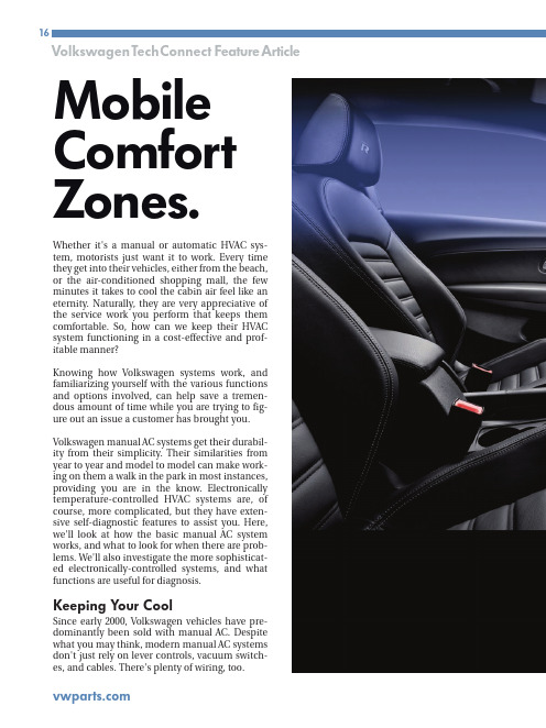
Whether it's a manual or automatic HVAC sys-tem, motorists just want it to work. Every time they get into their vehicles, either from the beach,or the air-conditioned shopping mall, the few minutes it takes to cool the cabin air feel like an eternity. Naturally, they are very appreciative of the service work you perform that keeps them comfortable. So, how can we keep their HVAC system functioning in a cost-effective and prof-itable manner?Knowing how Volkswagen systems work, and familiarizing yourself with the various functions and options involved, can help save a tremen-dous amount of time while you are trying to fig-ure out an issue a customer has brought you. Volkswagen manual AC systems get their durabil-ity from their simplicity. Their similarities from year to year and model to model can make work-ing on them a walk in the park in most instances,providing you are in the know. Electronically temperature-controlled HVAC systems are, of course, more complicated, but they have exten-sive self-diagnostic features to assist you. Here,we'll look at how the basic manual AC system works, and what to look for when there are prob-lems. We'll also investigate the more sophisticat-ed electronically-controlled systems, and what functions are useful for diagnosis.Keeping Y our CoolSince early 2000, Volkswagen vehicles have pre-dominantly been sold with manual AC. Despite what you may think, modern manual AC systems don't just rely on lever controls, vacuum switch-es, and cables. There's plenty of wiring, too.Mobile Comfort Zones.Manual AC systems are called that these days because there is no computer-controlled feed-back to adjust cabin temperature. The passengers simply set a temperature and the system puts out what it can to achieve it. Some electrical inputs are used to protect compressor operation. There is an ambient temperature sensor, a refrigerant pressure sensor, and coolant temperature sensor to make sure conditions are right to turn it on.Starting in the early 2000 model year, a cooling fan control unit monitors all these sensor inputs and manages the compressor clutch circuit as well as the cooling fans.With a manual system, all of these inputs need to be working properly to activate the compressor. If any input were to fail, the compressor clutch cir-cuit would open. Without a control unit with self-diagnostic capability, this means each input has to be checked using pin voltages. Whether you want to check the voltage signals at the cooling fan control unit, or each individual sensor, is up to you. The control unit is usually mounted on the driver’s side front frame rail. On a New Beetle,that would be under the battery tray, not all that easy to get to. Some cooling fan control units have strip-type fuses secured to the top, some do not, depending on the application.Testing InputConsider a 2002 J etta VR6 with manual AC. Itscoolant fan control unit has two connectors, oneA happy customer is a comfortable one. Y ouperform essential services to keep them rolling, but one indulgence they really enjoy is climate control.Here's how to keep them as comfortable in their vehicles as they are in their homes.four-pin, and a larger 14-pin. On the four-pin connector, you have the relay’s power supplies, a 6.0 millimeter solid Red in pin #1, and a 2.5mil-limeter R/Wtracer in pin #3. They should have battery voltage at all times. In pin #2 (a 2.5 mil-limeter R/W tracer) is the power supply out of the relay for low-speed fan operation. The final 6.0millimeter R/W tracer is the power supply output for the high-speed fan.The 14-pin connector is where the internal relays get activated, not only for the cooling fan, but also for the AC compressor clutch. Pin #6 is a Brown ground wire, and constant battery voltage comes in on pin #4, a R/Gr tracer. Power from the ignition switch comes in on in pin #9, usually a Bk/Bl tracer.In order for the compressor to turn on, inputs are needed. The first check is on pin #8, a Bl/R tracer. When the AC button is pressed and the blower is commanded on, you should see bat-tery voltage. Next, look at pin #2, a W wire. This is an unusual signal in that it is a five-volt square wave created by the refrigerant pressure sensor.The duty cycle of the signal will change with the refrigerant charge. This is to indicate if the charge is too low or too high to turn on/off and damage the compressor.Another signal that may inhibit compressor acti-vation is that of the ambient temperature switch. Test for voltage between pins #5 (Bl/R)and #14 (Gn/Bl). If the signal indicates the air temperature is too low, it will not allow the com-pressor to run. Check these inputs to the cooling fan control unit whenever the compressor clutch won't engage.A Brief Description of Climate ControlThe phrase "Automatic Climate Control" means that after setting the temperature in the cabin,an electronic unit monitors both outside and cabin temperature conditions and uses a pro-grammed plan for how best to achieve and maintain the chosen setting. These settings vary from full defrost heat to MAX AC. Once a tem-perature is set, the control unit will automatical-ly manipulate mode doors, temperature blend doors, and the recirculation door. There are manual overrides the passengers can select to control the mode doors' position, cabin air recirculation, and AC compressor operation.Since the electronics are overseeing system operation, Volkswagen has implemented the same self-diagnostic features found in other on-board control units.This is an ambient air temperature sensor found on an automatic climate control system, and is not to be confused with the ambient air temperature switch found on manual system. This sensor will only flag a code and affect temperature control. It will not suspend compressor operation.You may not realize what your current scan tool is capable of. You may not even realize how much useful information you have at your fin-gertips. You should hone your skills, reduce yourdiagnostic time and maybe get ahead of the “cost-effective diagnosis” game.Volkswagen/Audi Automatic Climate Controlled Systems are endowed with similar self-diagnostic features to powertrain control systems. While the scan-based diagnostic features in the Auto-HVAC systems are extensive, the interface is propri-etary, so without knowing what you are looking for it will be difficult to interpret the data being displayed. So how does this work?For those of you familiar with VAG scan-based diagnostics, this will be a review. For those not familiar with it, welcome to the future. VAG is the factory proprietary scan tool for Volkswagen and Audi vehicles. If you purchase the European bun-dle for your aftermarket scan tool, you should be able to display this “factory” software, which allows you to communicate with all of the various control units in the vehicle. Each control unit is programmed to use the same software architec-ture, so what we're about to describe will work onABS, as well as SRS.As you can see, there are many “address words”for all of the possible self-diagnostic systems on the vehicle. Select address word 08 – HVAC and you can talk to an automatic climate control sys-tem (not a manual system).The famous three dials of the Volkswagen HVAC system tell us when the AC button is pushed and the blow-er motor is turned on. The switch provides voltage to pin #8 on the cooling fan control unit indicating that AC has been requested.• Function 4 provides ‘basic settings.”• Function 5 clears codes.• Function 6 ends communication with the control unit.• Function 7 allows you to code the control unit to the particular car it is in.• Function 8 is for reading data.There are a few other functions to choose from,but we are going to focus on the most important ones.Starting with function 01, you will see that this merely identifies the control unit in the vehicle as well as its version coding. This information is useful if you feel the coding may have been changed in error, or a used control unit was installed and may not match the requirements of communicating with all of the other various con-trol units in the vehicle. Each control unit is pro-grammed to use the same software architecture,so what we're about to describe will work on ABSas well as SRS. You can enter the self-diagnosticOn the side of the cooling fan control unit, the pins are identified with their functions. You may be able to use them for testing once you learn what they are. Note that both strip and ATC fuses can be blown and prevent AC and cooling fan operation.You can enter the self-diagnostic feature with your scan tool by simply picking the address word you need. So, what’s an address word? With the factory scan tool, a series of numbers is used to identify the various systems we can enter. These numbers are called “address words” in your tech-nical literature.FunctionsEach system has its own address word. On the Volkswagen/Audi factory tester, you need to know what address word represents each system.Aftermarket diagnostic tools give the address word as well as a description of the system. In the case of automatic climate control, the address word is 08 (Auto – HVAC). Once you’ve selected the system, you will now be asked to select what function you would like to perform. You have numerous choices:• Function 01 identifies the control unit.• Function 2 is for pulling codes.• Function 3 is for actuation mode.feature with your scan tool by simply picking the address word.Providing the control unit is the proper one, you can correct coding if necessary. Function 02 is pretty self-explanatory. Auto-HVAC units are capable of self-diagnosis, and can identify faults in one or more components. These com-ponents are either sensor inputs, or actuator outputs. In the case of actuator outputs, you don't always have to access the component and start our testing there. The other option is scan tool activation.Function 03 is the mode in which you can take advantage of the scan tool and request that the HVAC control unit activate various outputs. You can listen for the activation, and/or perform elec-trical testing on the component being activated. This allows you to verify that the control unit’sdriver is capable of turning on any component in which you may suspect a fault.Moving along to function 04, this is referred to as “Basic Settings.” In general, this provides a “reset” or ‘re-sync” of computer-controlled fea-tures. The automatic climate control system needs to know the positions of the various tem-perature and mode doors in order to manipulate them if a change is requested by the occupant, or sensed by a temperature sensor. "Basic Settings" runs the control unit through the re-learn process, but more on this later.Function 05 simply clears codes, and once you are done communicating with the HVAC control unit, you need to shut down this communication by selecting Function 06. This prevents corrup-tion of software in the unit. Function 07 allows you to change the version coding, which is a way for you to tailor the control unit to the vehicle it is in. Vehicles come with more than one option. Each control unit must be made aware of these options in order to perform properly. This comes in especially handy when installing used parts. Although the replacement control unit may have the same part number, the coding must be changed to accommodate the requirements of the vehicle being repaired.Finally, Function 08 (sometimes referred to as data blocks, or measuring blocks) allows you to look at data, such as a temperature sensor read-ing, or actuator position. The tricky part is that these data blocks are also identified with num-bers and are displayed in blocks of four. You must look up in a table what the data blocks indicate for each display group.ResetOnce you have pulled codes, diagnosed a prob-lem, and done a repair, you may need to reset the climate control system, especially if a mode door motor was replaced. This can be achieved through the “Basic Settings” feature. You will be prompted to enter a three-digit code. Leave the code "000" in the display and enter this mode. The positions of the doors are recorded, and they will then cycle to their respective end stops. Now, the control unit knows what the maximum and minimum positions are for each mode/blend door. When it needs to make a temperature adjustment as a result of changing conditions, it can make the cor-rect change. Without knowing the proper position of the doors, it will make the wrong adjustment and output the wrong temperature.Knowing the system helps cut down on wasted diagnostic time, and can make you money on all but the most difficult problems. You will end up with fewer comebacks, less stress, and a cool,happy customerHere are your options once you have selected an address word. In 08, you can select “Basic Settings,” enter “000,” and the system will run through the initialization process. This should be performed after every mode door and tempera-ture blend door replacement.。
HVAC系统验证标准操作规程

标准操作规程STANDARD OPERATING PROCEDURE目的:检查并确认HVAC系统,确保其达到设计技术规范要求。
适用范围:HVAC系统的验证。
责任者:工程维修部、质量保证部程序:空气净化(HVAC)系统是由空气处理装置(包括热源)、空气输送和分配设备等组成的一个完整的系统,它能将空气处理成要求的状态后,送入指定的区域内,以满足该区域对室内温度、相对湿度、空气的气流速度及洁净度的要求。
1、HVAC系统测试仪器的校验1.1测量温度的仪表:(1)玻璃管液体温度计;(2)热电偶温度计1.2测量空气相对湿度的仪表:普通干湿球温度计1.3测量风速的仪表:(1)叶轮风速仪;(2)转杯式风速仪1.4测量风压的仪表:(1)U型压力计;(2)补偿式微压计1.5 HVAC常用的电工仪表:(1)转数表,用采测量风机、电机等设备的旋转速度:(2)空调常用的电工仪表(万用表.电压表.电流表.钳形电流表特表、单相调压器.标准电阻箱.微调电阻箱.惠斯发电桥等)1.6高效过滤器检漏用仪器:(1)检漏仪(光度计)加上DOP(邻苯二甲酸二辛酯)气溶胶发生器;共8页第2页(2)悬浮粒子计数器加上大气尘1.7洁净室洁净度测定用仪器:粒子计数器1.8细菌采样用的仪器:沉降菌采样仪器主要是Ф90mmxl5mm硼硅酸玻璃培养皿和普通肉汤琼脂培养基或其它药典认可的培养基。
1.9为保证设备运行正常、测试可靠,首先要检验测试仪器动作是否准确。
凡属仪表都必须进行校正,按照国家《计量法》的规定和验证的要求对计量仪表定期进行捡定,即使是标明符合国家标准的器具也不例外。
所有仪器仪表的校正必须在设备确认及环境监控前完成,并记录在案,作为整个验证的一个重要组成部分。
2、HVAC系统的安装确认(1Q)2.1 HVAC系统安装确认所需的文件(1)由质量部门及技术部门认可、批准的洁净室(区)平面布置图及空气流向图(包括各房间的洁净度,气流流向、压差,送、排风方式,温湿度要求,人流和物流流向。
HVAC系统培训资料

HVAC系统培训资料GMP增补培训课程空气处理系统HVAC是 Heating Ventilation and Air Conditioning 首字母的缩写,通称为供热,通风和空气调节.空气处理系统目的理解以下内容: 1. 制药行业中空气处理系统的需求和原因;2. 3. 4.空气处理系统的技术要求; 空气处理系统的不同类型; 确认和监控要求.第一部分第3 章第一部分:介绍和概况 1 of 20介绍和概况WHO - EDM第3 章第一部分:介绍和概况2 of 20WHO - EDM空气处理系统影响产品质量的因素:1. 2. 3. 4. 5. 6. 7.空气处理系统影响产品质量的因素已验证工艺程序人员原材料和包装材料已验证的工艺人员程序设备厂房的设计和质量制造环境原材料设备包装材料如果不能充分满足以上因素,将会导致产品质量不合标准.第3 章第一部分:介绍和概况 3 of 20WHO - EDM厂房环境第3 章第一部分:介绍和概况4 of 20WHO - EDM空气处理系统生产环境对于产品质量至关重要:1.空气处理系统什么是污染?污染是:1. 2. 3. 4. 5.照明温度湿度空气流动微生物污染微粒污染不受控制的环境会导致产品质量降级产品污染产品和利润的损失5 of 20WHO - EDM2. 3. 4. 5. 6. 7.所生产的产品以外的其它产品或物质外来产品微粒微生物内毒素 (微生物代谢产物之一)交叉污染是污染的一种特例.第3 章第一部分:介绍和概况 6 of 20WHO - EDM第3 章第一部分:介绍和概况空气处理系统交叉污染(1)什么是交叉污染? 交叉污染的定义: 在生产过程中,一种原材料,中间产品,成品与另外一种原材料或产品之间的污染现象. (世界卫生组织) 附件 1, 术语空气处理系统交叉污染(2)交叉污染的起源?1. 2. 3. 4.空气处理系统和除尘系统设计不当空气处理系统和除尘系统操作或保养不当人员和设备的操作程序不适当设备未充分清洁第3 章第一部分:介绍和概况7 of 20WHO - EDM第3 章第一部分:介绍和概况8 of 20WHO - EDM空气处理系统交叉污染(3)来自环境/操作者自身的污染物污染来自设备的污染物空气处理系统交叉污染(4)可以通过以下方法可将交叉污染降到最少:1. 2. 3. 4.人员的行为规范足够的厂房面积采用密闭式生产系统恰当并且经过验证的清洁方法适当的产品保护正确的气压气流分布10 of 20WHO - EDM来自环境/操作者自身的产品交叉污染来自设备的产品5. 6.第3 章第一部分:介绍和概况9 of 20WHO - EDM第3 章第一部分:介绍和概况空气处理系统保护等级的概念1.空气处理系统确定环境要求帮助防止污染和交叉污染使产品处于最佳的卫生环境重视产品对污染的敏感程度治疗风险生产环境要求其它级洁净等级级 C 洁净等级 A/B 级2. 3. 4.洁净等级 D治疗风险第3 章第一部分:介绍和概况 11 of 20WHO - EDM第3 章第一部分:介绍和概况12 of 20WHO - EDM空气处理系统保护等级几个参数:1.空气处理系统保护等级洁净厂房等级分类: 国际WHO 国家EC,PIC/S,TGA等US FDA ISPE 企业附件1, 17.3, 17.4 附件1, 17.3, 17.4空气洁净度要求 (过滤器类型和位置,空气换气次数,气流形式,差压,微粒和微生物的污染等级) 人流和物流方法生产操作允许的洁净等级建筑物的设计和装饰A,B,C,D A,B,C,D 重要的和受控的 1,2,3级或洁净区等级不尽相同2. 3. 4.第3 章第一部分:介绍和概况13 of 20WHO - EDM第3 章第一部分:介绍和概况14 of 20WHO - EDM空气处理系统保护等级制药设施内的所有运行与洁净厂房的洁净等级是密切相关的,并一起纳入了卫生概念之中. 例如:容器的清洗最终灭菌产品的溶液配置无菌灌装产品的溶液配置容器的去热原处理最终灭菌产品的灌装无菌产品的灌装其它 X X X X X X X空气处理系统保护等级根据洁净厂房的洁净级别要求,必须建立不同的保护等级,其中包括: 工艺操作和洁净级别的关联性在各保护等级区内允许的操作类型洁净厂房的洁净等级A B C D X洁净厂房的洁净级别定义(参数,建筑材料,房间要求,空调系统) 在不同级别的洁净厂房内,人员和物料的要求(服装,培训,物料类型等) 人员和物料入口状态的要求(更衣的步骤)附件 1, 17.3, 17.4, 17.515 of 20WHO - EDM第3 章第一部分:介绍和概况第3 章第一部分:介绍和概况16 of 20WHO - EDM空气处理系统影响保护等级的参数(1)空气处理系统空气处理系统影响保护等级的参数(2)1 2 3 4空气中的微粒数空气中和设备表面上的微生物数量每个房间的换气次数空气流速气流形态过滤器 (类型,位置) 房间之间的差压温湿度18 of 20WHO - EDM送风有确定要求的生产房间排风5 6 7附件 1, 17.48第3 章第一部分:介绍和概况17 of 20WHO - EDM第3 章第一部分:介绍和概况空气处理系统影响保护等级的参数(3)空气处理系统影响保护等级的参数(4)按关键参数定义的洁净厂房等级空气处理系统: 是达到所需参数的主要工具但是仅仅有它还不够完整还必需附加一些措施适当的更衣(衣服的类型,合适的更衣间) 经验证的清洁和消毒处理程序合适的人员和物料传输程序附件 1, 17.10 至 17.16空气处理系统附加措施第3 章第一部分:介绍和概况19 of 20WHO - EDM第3 章第一部分:介绍和概况20 of 20WHO - EDMGMP增补培训课程空气处理系统HVAC是 Heating Ventilation and Air Conditioning 首字母的缩写,通称为供热,通风和空气调节.空气处理系统空气处理系统的目的空气处理系统第二部分第3 章第二部分:构成 21 of 20构成WHO - EDM送风具有规定要求的生产房间排风第3 章第一部分:介绍和概况22 of 20WHO - EDM空气处理系统目的通过以下内容,我们来学习空气处理系统的构成:1. 2. 3. 排风空气处理系统主要的子系统熟悉系统构成了解它们的功能知道可能的问题空气处理单元补充新风+ 生产房间末端空气处理生产房间第3 章第一部分:介绍和概况23 of 20WHO - EDM第3 章第一部分:介绍和概况24 of 20WHO - EDM空气处理系统构造概况排风格栅消音器流量控制器风机过滤器空气处理系统构件(1)防水百叶风口防止昆虫,树叶,灰尘和雨水进入降低空气循环/气流产生的噪声自动调整风量(根据昼夜,压力等来控制) 固定的风量调节阀防水百叶风口控制风阀加热器消声器末端过滤器+预过滤器加湿器流量控制器控制风阀冷盘管及二级过滤器挡水板热盘管再循环空气生产房间第3 章第一部分:介绍和概况25 of 20WHO - EDM第3 章第一部分:介绍和概况26 of 20WHO - EDM空气处理系统构件(2)加热单元制冷单元/ 除湿器加湿器过滤器风管加热空气到适当温度冷却空气到要求的温度或除去空气中的水分流速控制器控制风阀加湿器如果空气湿度太低,将空气加到适当湿度冷盘管除去预定尺寸的颗粒和/或微生物过滤器输送空气风管27 of 20WHO - EDM空气处理系统部件常出现的问题堵塞调节不良,压差系统不正常水/汽质量不好/排水不畅不能去除空气露水/排水不畅选用等级不正确/损坏/安装不当不适当的材料/内部保温处的泄漏第3 章第一部分:介绍和概况第3 章第一部分:介绍和概况28 of 20WHO - EDM空气处理系统空气类型粒子数 / 立方米空气处理系统国际洁净区级别比较US 209D 英制≥ 0 .5 m 1 3 ,5 10 35 100 353 1 .0 0 0 3 .5 3 0 US 209E 1992 公制欧盟 cG M P 附件 I 1997 德国 VDI 2083 1990 英国 BS 5295 1989 日本 J IS B 9920 1989 IS O 1 4 6 4 4 -10 1 10 100 M M M M M M 1 1 .5 2 2 .5 3 3 .5 1 2 A, BA= 单向流 B= 乱流2 3 4 E or F 52 3 4 5新风 (补充新风)送风+排风3生产房间回风再循环1 0 .0 0 0 3 5 .3 0 0 1 0 0 .0 0 0 3 5 3 .0 0 0 1 .0 0 0 .0 0 0 3 .5 3 0 .0 0 0 1 0 .0 0 0 .0 0 01 .0 0 0 1 0 .0 0 0 1 0 0 .0 0 0M M M M M M M4 4 .5 5 5 .56 6 .5 74 C D5 6G or H J K6 7 86 7 8第3 章第一部分:介绍和概况29 of 20WHO - EDM第3 章第一部分:介绍和概况30 of 20WHO - EDM空气处理系统过滤器分类标准空气过滤器气溶胶测试F9空气处理系统过滤器的分类(按照过滤效率划分)平均效率整体效率捕获率% 穿透率85 95 99.5 99.95 99.995 0.15 0.05 5x10⁻³ 5x10⁻⁴ 5x10⁻⁵ 97.5 99.75 99.975 25x10-3 25x10-4 25x10-5 最大捕捉率逐点效率效率穿透率初效Dp > 10 m中效10 m > Dp > 1 m高效Dp < 1 m超高效H11 H12G1 - G4F5 - F9H 11 - 13U 14- 17H13 U14EN 779 标准EN 1822 标准第3 章第一部分:介绍和概况31 of 20WHO - EDM第3 章第一部分:介绍和概况32 of 20WHO - EDM空气处理系统加湿器高效/第三级过滤器空气处理系统消音器加热和冷却单元初效平板式过滤器中效/第二级过滤器第3 章第一部分:介绍和概况 33 of 20 WHO - EDM第3 章第一部分:介绍和概况34 of 20WHO - EDM空气处理系统1 2空气处理系统带终端过滤器的漩流型散流器空气流量调节阀潮湿的房间空气吸附轮干空气AHU风机的变速控制器3 4再生空气潮湿的房间空气过滤器压差表空气加热器除湿机第3 章第一部分:介绍和概况 35 of 20空气处理单元WHO - EDM1 2 3 4过滤器固定框架通风口通风口大小调节螺丝36 of 20WHO - EDM第3 章第一部分:介绍和概况空气处理系统办公用柯恩达效应散流器漩流散流器空气处理系统房间压力调整-压差概念减少诱导气流诱导房间空气与送风混合回风回风回风回风房间压力表高诱导办公型散流器 (避免)第3 章第一部分:介绍和概况 37 of 20 低诱导漩流型散流器 (首选)WHO - EDM房间压力表面板附录 1, 17.26第3 章第一部分:介绍和概况 38 of 20 WHO - EDM空气处理系统注射剂压力梯度的设置以防止微粒和微生物的进入1#房间1#房间30 Pa 60 Pa空气处理系统固体制剂压力梯度的设置以防止交叉污染2#房间15 Pa3#房间15 Pa2#房间3#房间45 Pa15 PaLFD气闸室45 Pa气闸室B C气闸室气闸室气闸室30 Pa15 Pa 30 PaD过道气闸室0 PaE0 Pa 15 Pa过道备注:房门开启方向与压差有关附件1, 17.24, 17.25WHO - EDM备注: 房门开启方向与压差有关第3 章第一部分:介绍和概况39 of 20第3 章第一部分:介绍和概况40 of 20WHO - EDMHongwu Guo: Hongwu Guo: Hongwu Guo: Hongwu Guo:GMP增补培训课程空气处理系统Hongwu Guo: Hongwu Guo:空气处理系统空气处理系统特性在下面内容中,我们将学习空气处理系统的一些要点: 乱流和单向流过滤器位置空气再循环与新风回风系统(位置) 正压要求HVAC是英文 Heating Ventilation and Air Conditioning 首字母的缩写, 通称为供热,通风和空气调节.第三部分第3 章第三部分:设计,确认和维护设计,确认和维护41 of 27WHO - EDM第3 章第一部分:介绍和概况42 of 20WHO - EDM空气处理系统气流组织方式(1)乱流稀释玷污的空气单向流/层流置换玷污的空气空气处理系统气流组织方式(2)净化空气进入生产房间或覆盖生产过程时可以是: 乱流单向流(层流) GMP方面经济方面新技术:隔离器技术0,30 m/s附件 1, 17.3第3 章第一部分:介绍和概况 43 of 20WHO - EDM附件 1, 17.3, 17.4第3 章第一部分:介绍和概况 44 of 20 WHO - EDM空气处理系统气流组织方式(3)预过滤器附件 1, 17.3空气处理系统气流组织方式(4)工作台(垂直层流) 通风柜吊顶安装空气处理单元主过滤器123乱流单向流乱流第3 章第一部分:介绍和概况45 of 20WHO - EDM第3 章第一部分:介绍和概况46 of 20WHO - EDM空气处理系统过滤器安装位置(1)空气处理单元内安装的末道过滤器终端过滤器高效过滤器空气处理系统过滤器安装位置(2)预过滤器空气处理单元主过滤器 +1生产房间高效过滤器生产房间吊顶排风口 2 3低位排风口第3 章第一部分:介绍和概况 47 of 20WHO - EDM第3 章第一部分:介绍和概况48 of 20WHO - EDM空气处理系统过滤器安装位置(3)空气处理单元预过滤器终过滤器空气处理系统空气再循环送入生产房间的净化空气可以被: 100% 排放一定比例再循环GMP方面经济方面附件 1, 15.10, 17.24149 of 202WHO - EDM第3 章第一部分:介绍和概况第3 章第一部分:介绍和概况50 of 20空气处理系统100%新风通风系统(无空气再循环)排风机组清洗设备(可选) 排风机组空气处理系统再循环风+新风的通风系统W中央空气处理机组生产车间中央空气处理机组附件 1, 17.24第3 章第一部分:介绍和概况 51 of 20WHO - EDM回风第3 章第一部分:介绍和概况 52 of 20WHO - EDM空气处理系统状态定义空态空气空气处理系统确认/验证要点动态好的设计是基本的,但是还必须补充以下部分:空气静态空气空气处理系统确认生产过程验证维护和周期性再验证足够的支持文档第3 章第一部分:介绍和概况53 of 20第3 章第一部分:介绍和概况54 of 20WHO - EDM空气处理系统(OQ,PQ)确认(1)测试过滤器压差房间压差气流速率/均匀性流量 / 总量平行性气流形态 IQ 测试未在此提及 2 N/A 2, 3 2 2 2 单向流 / LAF 2 2, 3 可选 2 N/A 3 1 = 空态 (执行IQ) 2 = 静态 (执行OQ) 3 = 动态 (执行PQ) 恢复时间房间级别 (空气微粒) 温度湿度测试乱流/ 混合流描述空气处理系统(OQ,PQ)确认(2)单向流 / LAF N/A 2 N/A 2乱流/ 混合流 1 = 空态 (执行IQ) 2 = 静态 (执行OQ) 3 = 动态 (执行PQ)描述2,3 2,3附件 1, 17. 4附件 1, 17. 4IQ 测试未在本页中提及第3 章第一部分:介绍和概况55 of 20WHO - EDM第3 章第一部分:介绍和概况56 of 20WHO - EDM空气处理系统微生物验证1. 2. 3.空气处理系统洁净室监控程序(1)洁净室要监测微生物和空气微粒行动限定义洁净区域报警/行动界限确定和标记采样点定义运输,储存和培养条件行动限报警限报警限空气请考虑此问题:"何为报警和行动界限, 如果这些限制点被超过要采取哪些行动? "设计条件正常运行范围运行范围-经验证的可接受标准采样点第3 章第一部分:介绍和概况57 of 20WHO - EDM第3 章第一部分:介绍和概况58 of 20WHO - EDM空气处理系统洁净室监控程序(2)日常的检测程序是质量保证的一部分附加的监控和行动条件1. 2. 3. 4.空气处理系统洁净室维护程序(1)证明持续符合的测试时间表测试参数微粒计数测试洁净度 A, B <= ISO 5 C, D > ISO 5 所有级别所有级别最大时间间隔 6月 12 月 12 月 12 月测试程序 ISO 14644 -1 附录 A ISO 14644 -1 附录 A ISO 14644 -1 附录 B5 ISO 14644 -1 附录 B4停机过滤器元件更换空调系统维护超过既定的界限压差测试空气流量测试附件 1, 17.37第3 章第一部分:介绍和概况59 of 20WHO - EDM第3 章第一部分:介绍和概况60 of 20WHO - EDM空气处理系统洁净室维护程序(2)附加可选测试时间表测试参数已安装过滤器的泄漏测试密闭性泄漏测试恢复气流可视化测试洁净度所有级别所有级别所有级别所有级别最大间隔 24 月 24 月 24 月 24 月测试程序 ISO 14644-1 附录 B6 ISO 14644-1 附录 B4 ISO 14644-1 附录 B13 ISO 14644-1 附录 B7空气处理系统文件要求安装和功能描述技术规范明细操作程序性能控制手册维修手册和档案维护记录人员培训 (计划和记录)第3 章第一部分:介绍和概况61 of 20WHO - EDM第3 章第一部分:介绍和概况62 of 20WHO - EDM空气处理系统检查空气处理设备1.空气处理系统结论空气处理系统: 在制药质量方面扮演主要角色必须有专业人员进行合理设计必须作为重要系统对待检查设计文件,包括:安装和功能描述要求的详细说明2. 3. 4. 5. 6. 7. 8.操作程序维修手册维修记录培训日志环境记录数值超限后的纠偏行动讨论巡视整个工厂63 of 20WHO - EDM第3 章第一部分:介绍和概况第3 章第一部分:介绍和概况64 of 20WHO - EDM空气处理系统进一步行动完成了一系列的解释,现在要做的是: 小组讨论,做一个简单练习测验气闸室1 风淋室仓库取样间空气处理系统小组讨论服务走廊(包含真空和RO水供应)气闸室2称重间压片间1压片间2液体混合间软胶囊包装级区走廊应急出口男更衣室2 无菌滴眼液配料和无菌灌装女更衣室2 已包装产品隔离间滴眼液 2级人员入口内外包装气闸室3设备清洗间男更衣室1女更衣室1气闸室4服务间第3 章第一部分:介绍和概况65 of 20WHO - EDM第3 章第一部分:介绍和概况66 of 20WHO - EDM空气处理系统小组讨论–调整后的平面布局20Pa取样室0Pa 30Pa服务走廊(包含真空和RO水供应) 30Pa风淋室20Pa 10Pa称量间传递间20Pa 30Pa仓库0Pa物料缓冲1ISO 9级或 E级区物料缓冲2压片间115Pa压片间215Pa液体混合间30Pa软胶囊包装气闸室15Pa 30Pa级区走廊应急出口人员缓冲物料缓冲340Pa 40Pa20Pa20Pa男更衣室2女更衣室210Pa无菌滴眼液配料和无菌灌装10Pa 10Pa 60Pa已包装产品隔离间外包装20Pa内包装30Pa15Pa物料缓冲450Pa更衣室50Pa设备清洗间男更衣室1女更衣室1气闸室0Pa服务间0Pa0Pa第3 章第一部分:介绍和概况67 of 20WHO - EDM。
- 1、下载文档前请自行甄别文档内容的完整性,平台不提供额外的编辑、内容补充、找答案等附加服务。
- 2、"仅部分预览"的文档,不可在线预览部分如存在完整性等问题,可反馈申请退款(可完整预览的文档不适用该条件!)。
- 3、如文档侵犯您的权益,请联系客服反馈,我们会尽快为您处理(人工客服工作时间:9:00-18:30)。
江阴利港发电股份有限公司4×600MW超临界机组#5、6机组H V A C系统调试大纲编写:郭军、周君华审批:江阴利港发电股份有限公司华北调试所二〇〇五年九月报告名称:江阴利港发电股份有限公司三期扩建工程HVAC系统调试大纲报告编号:2005-汽机-21调试单位:江阴利港发电股份有限公司华北电力调试所#3CC无锡新启元空调工程公司麦克维尔制冷空调有限公司无锡居里SIEMENS楼宇自控项目部山东北辰集团有限公司江苏江平空调设备有限公司浙江联丰风机有限公司报告日期:2005年9月4日星期日调试日期:2005年9月~10月目录一、系统调试概要二、调试系统设备三、调试、试转条件四、调试仪器、仪表五、系统单项分步试转六、风量标定和风量平衡试验七、BAS系统的联调八、HVAC系统整体功能验收江阴利港发电股份有限公司五、六号机组HVAC系统调试技术措施一、系统调试概要1、主体工程概要:江苏利港电力有限公司一二期工程安装了4台350MW燃煤汽轮发电机组。
其中一期工程2×350MW机组于1993年建成投产,二期工程2×350MW机组于1998年建成投产。
本期工程计划安装4×600MW超临界燃煤汽轮发电机组。
1.1厂址江苏利港电力有限公司厂址位于江苏省无锡市江阴市区以西利港镇境内,厂址北临长江,位于长江江阴河段相对稳定处,长江深水航道靠近南岸。
从长江大堤向南约2km为利港镇。
电厂距主要负荷中心城市江阴市约17km,距无锡市约55km,距常州市约20km。
厂址周围地势平坦,平均海拔高度为4.1m~4.3m(吴淞高程)。
主厂房零米海拔高度为4.6m(吴淞高程)。
1.2 厂区的岩土工程条件根据地质资料,厂区第四系冲积层厚约180m,下卧基岩为白垩系红砂岩。
所揭露的地层自上而下为:人工填土、粉质粘土、淤泥质粉质粘土、粉土、粉砂、细砂、粗砂等。
1.3 地震烈度根据中国地震动参数区划图GB18306—2001,建筑抗震设计规范GB50011—2001,厂址抗震设防烈度为6度;地震动峰值加速度(设计基本地震加速度)为0.05g;设计地震为第一组。
1.4 运输利港电厂对外交通运输条件较好,本期工程的交通运输以水路为主,公路运输为辅,铁路运输可在邻近的常州站及镇江站卸货后经公路中转。
本期工程的大件设备运输利用一、二期工程的大件码头卸货。
厂址公路运输十分便利,沿江公路距厂址约1公里,电厂距江阴市约17km,距无锡市约55km,距常州市约20km。
1.5 燃料:燃用神华混煤、淮南煤。
1.6 水源:电厂循环冷却用水以长江水作为水源。
电厂厂址位于长江江阴河段,该河段水量充沛,河床和岸线基本稳定。
1.7 电厂厂用电源种类和参数:1.7.1 不停电电源:交流单相220-230V1.7.2控制电源:交流单相220V +10%,-15%1.7.3动力用直流电源:220V ,+10%,-15%1.7.4 厂用电动机电源:小于200kW 电压380-400V大于等于200kW 6000-6300V电压2、HVAC工程概要2.1设计气象参数冬季采暖室外计算温度-2℃冬季通风室外计算温度2℃冬季空调室外计算温度-5℃极端最低温度-11.4℃日平均温度低于+5℃的天数67d最冷月平均相对湿度74%冬季室外平均风速 4.3m/s最大冻土层深度7cm夏季通风室外计算温度32℃夏季空调室外计算温度33.8℃夏季空调室外计算湿球温度28.4℃空气调节日平均温度31℃极端最高温度38℃最热月平均相对湿度84%夏季通风室外计算相对湿度71%夏季室外平均风速 3.7m/s 年平均温度15.2℃2.2 空调室内设计工况2.3系统设计概要江阴利港发电股份有限公司三期扩建工程HVAC系统包括:●集中制冷、冷却系统●集中空调系统●集中通风系统●通风、防排烟系统●采暖加热系统●汽机房自然通风系统●BAS楼宇自动控制系统(SIEMENS楼宇系统)2.3.1集中制冷、冷却系统集中制冷站设置在集控楼内,采用2台单螺杆冷水机组,每台制冷机的容量为1200KW,为空调机组、通风降温机组、风机盘管提供7~12℃的冷冻水;冷却塔为闭式冷却塔,冷却水量为300T/H,冷却能力为1745KW。
制冷系统如下工艺设备:2台螺杆压缩制冷机、2台冷却水泵、2台冷冻水泵、2台冷却塔系统、2台全自动除垢仪、补水箱、8个电动调节阀、20个电动蝶阀及管网等构成。
冷却塔系统由如下工艺设备构成:3台风机、2台循环水泵、一个水箱及数个电动阀门构成。
运行方式均为一投一备。
2.3.2 集中空调系统集中空调系统工艺流程:2台组合式空调机组、数个防火阀及数个电动阀门等构成。
回风机兼做消防后排烟用。
空调系统采用上送,上回地气流组织方式。
空调机组的构成包括回风机段、带调节挡板的新风段和回风混合段、初效过滤器段、中间段、中效过滤器、表冷段、电加热器段、中间段、热水加热段、加湿段、送风机段以及必要的检修门和必要的检修照明组成。
空调机组的工艺设备:1台送风机、1台回风机、1台电加热器、1台加湿泵、1个新风电动调节阀、1个排风电动调节阀、1个混合风电动调节阀、1个表冷电动调节阀、1个加热电动调节阀、1个加湿电动调节阀、1个送风电动门、1个回风电动门等;其中新风由新风机组提供。
新风机组的工艺设备:3台送风机、3个送风电动门。
运行方式均为一投一备。
2.3.3集中通风系统集中通风系统工艺流程系统为集中送风和就地排风设计,组合通风降温机组采用板块结构,它由送风机段,过滤段,表冷段,新风段组成。
由2台组合式通风机组、数个防火阀及数个电动阀门等构成。
通风降温机的组工艺设备:1台送风机、1个新风电动阀、1个表冷电动调节阀、1个送风电动门;运行方式为:一台为集控楼OM配电间送风,就地排风机排风;另一台为集控楼6.9M配电间,就地排风机排风;2.3.4通风、防排烟系统电缆夹层设自然进风,机械排风系统。
柴油机房,仪用空压机房、化学水处理、化学配电间和HVAC机房为自然进风,机械排风;冬季时设散热器以维持室内要求。
2.3.5 汽机房自然通风系统汽机房采用自然通风为主的通风方式。
自然通风系统由汽机房0M、6.9M层电动百叶窗和汽机房顶屋顶通风器及排氢风帽构成。
每台汽机房的自然通风系统有如下工艺设备:1台屋顶通风器(每台约75米)、数个电动百叶窗等,电动百叶窗成组控制。
每台屋顶通风器有13或14个电动阀,屋顶通风器分奇/偶数控制。
2.3.6 BAS楼宇自动控制系统(SIEMENS楼宇系统)系统采用楼宇级网路BLN和现场总线结构,其中楼宇级网路(BLN)是BAS系统的核心。
BLN网路中设计MBC01~07共7个就地盘,控制就地系统地运行,在控制室内设置INSIGHT主机监视和操作各区域地运行。
控制软件(INSIGHT3.6)由SIEMENS供货,上海SIEMENS和无锡居里公司共同设计。
BLN网路采用RS-485类型。
2.3.7其他汽机房电气设备间、电除尘配电间、蓄电池、网控继电器室、储煤筒仓配电间:设置分体空调机为主和自然进风、机械排风为辅的方式;化学控制室设计为屋顶空调机组的小型中央空调系统。
输煤综合楼采用多联空调系统达到设计要求制氢站控制室设有分体柜式小型空调机组,二、HVAC系统主要设备三、试转条件1、工作现场整洁,场地平整,风道孔洞盖板齐全,道路畅通,照明充足;2、现场备有足够的消防器材;3、HVAC系统安装完毕;4、临时水源――除盐水及冷凝水疏水完善;5、提供500KW的临时动力电源;提供电源表:6、提供一路380V~电源:6.9MHVAC控制室启用,受电。
并向BAS提供控制盘电源220V~。
7、冷、热水管路必须进行冲洗、试压,所有手动阀门、电动调门在静态位置。
8、水管道、风管道保温完毕;9、风管道内所有的调风挡板、消防挡板、手动、电动挡板在正常运行位置;10、电气一次、二次系统的接线完好,各项性能符合设计要求;11、控制系统所有的温度、压力表计及其开关,温度,湿度传感器,低温极限开关,电动通断门,电动调门,流量开关,各新风、回风、混合挡板执行器等的信号、动作准确;各表计校验合格;12、控制主机与各就地盘MBC01~07、制冷机控制PLC、换热机组控制PLC的分布式数字通讯系统连接准确。
13、制冷机组安装位置、标高符合设计要求,地基、支架牢固。
连接管路的材质、规格、尺寸符合设计要求。
14、安装单位提供电机的绝缘、空转电流数据单,电加热器、其他电气回路的绝缘,管路试压、冲洗报告。
15、调试人员备有必须的操作工具和通讯工具。
四、调试用仪器、仪表1、485数字温湿度计2、测震仪3、钳型电流表4、万用表5、毕托管6、测转速仪7、471风速流量计8、475压差测量仪五、系统单项试车前检查5.1冷却水/冷冻水系统冲洗和排污技术措施5.1.1冷却水系统冲洗和排污技术措施5.1.1.1安全措施:●断开制冷机A/B动力电源,并挂”禁止合闸”操作牌;●断开冷却塔A~F风机/循环泵电源并挂”禁止合闸”操作牌;●确认冷却水泵电源与信号均正常;●确认冷却水变频补水装置电源已经送上,信号已经正常;●确认冷却水多功能除污器电源已经送上,信号已经正常;5.1.1.2冷却水管路冲洗:5.1.1.2.1临时措施:●关闭A/B侧冷却塔12个进出水电动门,关闭制冷机A/B冷却水进回水门(4只电动);●在A组进出水门间加一路临时旁路;在A制冷机冷却水进回水门间加一路临时旁路;5.1.1.2.2冲洗排污:●启动冷却水变频补水装置系统冲压,打开冷却塔进回水排污门或松开进回水门前螺栓进行排污至清澈;●检查多功能除污器滤网压差及自动除污工作情况,保证工作正常;●如果除污器工作正常,检查冷却水管路:●补水装置运行正常;●冷却塔、制冷机进出水阀门可靠关闭;●临时旁路正常,排污门、口及临时解除的排污口关闭,各仪表口、漏点已经消除;●执行冷却水泵A/B预启动检查卡;●消除预检查卡中的缺陷或问题后,执行冷却水泵A/B启动检查卡,启动冷却水泵,彻底检查冷却水系统,加强自动除污器的运行检查,必要时手动排污合清理杂物。
5.1.1.2.3清理恢复:●停冷却水泵、补水装置及冷却水系统:解开下列门,全面清理门前的杂物,A/B侧冷却塔12个进出水电动门,制冷机A/B冷却水进回水门(4只电动)●清理完毕后恢复临时措施,启用冷却水系统进行冷却水回路正常循环,全面检查系统漏点、除污器、补水装置工作情况,冷却水投入正常状态。
5.1.2冷冻水系统冲洗和排污技术措施5.1.2.1安全措施:●断开制冷机A/B动力电源,并挂”禁止合闸”操作牌;●确认冷冻水泵电源与信号均正常;●确认冷冻水变频补水装置电源已经送上,信号已经正常;●确认冷冻水多功能除污器电源已经送上,信号已经正常;5.1.2.2冷冻水管路冲洗:5.1.2.2.1临时措施:●关闭制冷机A/B冷冻水进回水门(4只电动);●关闭进入空调机组、通风降温机组和风机盘管的进出水门,当无门时加堵板及临时旁路;●在A组进出水门间加一路临时旁路;在A制冷机冷却水进回水门间加一路临时旁路;5.1.2.2.2冲洗排污:●启动冷冻水变频补水装置系统冲压,打开集水器、分水器排污门或松开进回水门前螺栓进行排污至清澈;打开集水器和分水器之间的旁路门;●检查多功能除污器滤网压差及自动除污工作情况,保证工作正常;●如果除污器工作正常,检查冷冻水管路:●补水装置运行正常;●空调机组、通风降温机组、制冷机进出水阀门可靠关闭;●临时旁路正常,排污门、口及临时解除的排污口关闭,各仪表口、漏点已经消除;●执行冷却冻泵A/B预启动检查卡;●消除预检查卡中的缺陷或问题后,执行冷冻水泵A/B启动检查卡,启动冷冻水泵,彻底检查冷冻水系统,加强自动除污器的运行检查,必要时手动排污合清理杂物。