KMM372V213CK中文资料
N9二极管规格 1SS372(SOT-323)
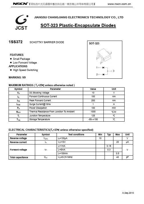
SOT-323
FEATURES Small Package Low Forward Voltage APPLICATIONS High Speed Switching
MARKING: N9
MAXIMUM RATINGS ( Ta=25℃ unless otherwise noted )
Symbol
Parameter Reverse voltage Reverse current
Forward voltage
Total capacitance
Symbol V(BR) IR
VF
Ctot
Test conditions IR=100μA VR=10V IF=1mA IF=5mA IF=100mA VR=0V,f=1MHz
Parameter
VR
DC Blocking Voltage
IO
Forward Continuous Current
IFM
Peak Forward Current
IFSM
Surge Current@10ms
PD
Power Dissipation
RθJA
Thermal Resistance From Junction To Ambient
Tj
Junction Temperature
Tstg
Storage Temperature
Value 10 100 200 1 100
1000 125 -55~+150
Unit V mA mA A
mW ℃/W
℃ ℃
ELECTRICAL CHARACTERISTICS(Ta=25℃ unless otherwise specified)
UT371 372 操作手册说明书

Model UT371/372 OPERATING MANUALTABLE OF CONTENTSTITLE PAGE 334567891113131517Overview Unpacking Inspection Safety Information Rules For Safe Operation International Electrical Symbols The Meter Structure Functional Buttons Setup Display Symbols Measurement Operation A. RPM Measurement B. Counts C. Data Transferring and USB 1TABLE OF CONTENTSTITLE PAGE 181819202020212122Specifications A. General Specifications B. Environmental Requirements Accuracy Specifications A. RPM B. Counts Maintenance A. General Service B. Replacing the Battery 2Model UT371 and UT372 is a stable, safe and reliable digital non-contact Tachometer.This Tachometer can measure RPM and counts. RPM range is 10 ~ 99999 while counts range is 0 ~ 99999.Open the package case and take out the Meter. Check the following items carefully to see any missing or damaged part:Description English Operating Manual Reflecting Tape USB Interface Cable (UT372 only)Software(UT372 only)1.5V Battery (LR6)OverviewThis Operating Manual covers information on safety and cautions. Please read the relevant information carefully and observe all the Warnings and Notes strictly.Item 12345Qty1 piece10 pieces 1piece1 piece4 piecesUnpacking Inspection3In the event you find any missing or damage, please contact your dealer immediately. Safety InformationThis Meter complies with the standards IEC61010-031, IEC61326, : in pollution degree 2Use the Meter only as specified in this operating manual, otherwise the protection provided by the Meter may be impaired.In this manual, a Warning identifies conditions and actions that pose hazards to the user, or may damage the Meter or the equipment under test.A Note identifies the information that user should pay attention to.International electrical symbols used on the Meter and in this Operating Manual are explained on page 6.4Rules For Safe OperationBefore using the Meter inspect the case. Do not use the Meter if it is damaged or the case (or part of the case) is removed. Look for cracks or missing plastic.Do not use or store the Meter in an environment of high temperature, humidity,explosive, inflammable and strong magnetic field. The performance of the Meter may deteriorate after dampened.Do not point laser directly at eye.Replace the battery as soon as the battery indicator appears. When thebattery is between 4.5V ~4.8V, the battery indicator appears. When thebattery is between 4.3V ~ 4.5V, battery indicator blinking, the Meter will be turned off after 1 minute.When opening the battery door, must make sure the Meter is power off.When servicing the Meter, use only the same model number or identical electrical specifications replacement parts.The internal circuit of the Meter shall not be altered at will to avoid damage of the Meter and any accident.5Soft cloth and mild detergent should be used to clean the surface of the Meter when servicing. No abrasive and solvent should be used to prevent the surface of the Meter from corrosion, damage and accident.Turn the Meter off when it is not in use and take out the battery when not using for a long time.Constantly check the battery as it may leak when it has been using for some time, replace the battery as soon as leaking appears. A leaking battery will damage the Meter.International Electrical Symbols6Figure 1The Meter Structure (see figure 1)Tachometer Light Source.LCD Display.USB Port (UT372 only)HousingFunctional Buttons7Functional ButtonsBelow table indicated for information about the functional button operations.Button Operation Performedl Press once to turn the meter on.l Press and hold for 1 minute to turn it off.l When measuring RPM and Counts, press once to enter the Hold mode. Press it againto exit hold mode.l When measuring RPM and Counts, press it to toggle between RPM and Counts feature.l Press and hold for 1 minute to enter setup feature, the LCD displays USB. After that,each press to step through LED / SR / AOFF / CLK / exiting setup feature to enter RPMor Count. You could press ON/OFF button to exit setup mode and returning to normalmeasurement mode at any time.l Press this button to choose maximum reading, minimum reading, average reading,zerong, Tunel Under Tach measurement mode, press M/M/A button to select MAX/MIN/AVE andnormal value measurement,After entering USB/LED/SR/AOFF/CLK mode, press this button to setup 0 or 1 and time.l In the RPM or COUNT mode.press and hold the button for more than second therelative time will be clear and execute HOLD function In the COUNT mode pressing thebutton will be clear.ON/OFF R/C M/M/A 8SetupA. USB setupPress R/C button to select USB feature after turning on the Meter. Then press M/M/A button to setup 0 or 1. 0 means turn the USB off. 1 means enable the USB feature.B. LED setupPress R/C button to select LED feature after turning on the Meter. Then press M/M/A button to setup 0 or 1. 0 means turn the LED laser off. 1 means enable the LED laser feature.C. SR sampling rate setupPress R/C button to select SR feature after turning on the Meter. Then press M/M/A button to setup 005 ~ 255. Press and hold M/M/A button to access quick setting.D. AOFF setupPress R/C button to select AOFF feature after turning on the Meter. Then press M/M/A button to setup 0 or 1. 0 is disable auto power off feature. 1 means enable auto power off feature,After enable auto power off feature, the Meter will be auto power off after ten minutes9if you do not press any button for 10 minutes. You could press ON/OFF button to turn on the Meter again after the Meter is off.E. CLK setupPress R/C button to select CLK feature after turning on the Meter. Then press M/M/A button to setup 0 or 1. 0 is hours and minutes format. 1 is minutes and seconds format.10Display Symbols (see figure 2)Figure 2111 2 3 4 5 6 7 8 9 10 11 12Unit of TachometerUnit of CountsTimeThe battery is low.Indicator of Sleep Mode Measurement of RPM and Counts Data Hold is onDisplay of Maximum reading Display of Minimum reading Display of Average readingUSB is onDisplay of Measurement reading lNumber Meaning 12Warning WarningTo reserve battery, the USB feature will be automatically off when the Meter is restarted. The other setting remains unchanged.The Time will be off after the HOLD feature is enabled. The time will be on again after existing HOLD mode.l l A. RPM Measurement (see figure 3)l Do not point laser directly at eye.l When carrying out measurement, the distance must be more than 50mm.l To avoid hurt yourself or damage to the meter, do not let speedy rotary object to touch the Meter.Measurement Operation13Figure 3To carry out RPM measuremnet, follow thefollowing procedure:Apply a piece of reflecting tape to the objectunder test.Position the Meter on a flat place. Hold the Meter50~200mm from the Tachometer light source tothe object under test.Press ON/OFF button, the Meter is default toenter the RPM measurement mode. Point theTachometer light source to reflective tape, thevertical angle of the reflecting tape is not greaterthan 30°.The LCD displays the RPM reading.Note:When measuring RPM, the LCD displays “0.0000”if there is no signal for continuous 7 seconds.When the RPM reading is greater than 99999.the LCD displays OL.1.2.3.4.1.2.14Figure 4B. CountsSelf-lighted Counts (see figure 4)1. Position the Meter on a flat place. Hold theMeter 50~200mm and at the vertical angel notgreater than 30° from the Tachometer light sourceto the object under test.2. Press the ON/OFF button3. Press the R/C button to select Count mode.4. Point he Tachometer light source to the objectunder count5. The LED scans the object under count, theMeter accumulates the counts and displays thequantity.Note:1.The object under count must be reflective,otherwise Counts feature cannot be used 15Receiving Light Source Outside (see figure 5)Figure 5Position the Meter on a flat place. Hold the Meter50~200mm and at the vertical angel not greater than30° from the Tachometer light source to the object undertest.Set up the Meter, object under counts and outside lightsource as figure 5Press ON/OFF buttonTurn the LED off, refer to page 9 point B.Then press R/C button to select Counts mode.The object under count passes through between theMeter and the outside light source, the Meter accumulatesthe counts and displays quantity.Note:Under the count mode, when the quantity is greaterthan 99999 RPM, the Meter displays OL and hold thedata.Press M/M/A button zeroing the Counts.Press ON/OFF to re-start Counting.1.2.3.4.5.6.1.2.3.16C. Data Transferring and USB (UT372 only, see figure 6)Connect the USB interface cable, the Meter and the computer as per the figure 6.Figure 617A. General Specificationsl Display: 5 digits LCD display, Maximum display 99999.l Overloading: Display OL .lBattery Deficiency: Display .l Sampling Rate: 5 mini-second to 255 mini seconds adjustable.l Transducer Tyype: Photo Diode and Laserl Measurement Distance: 50mm ~ 200mml Drop Test: one meterl Power: 4pcs x 1.5V batteries (AA)l Dimensions: 184 x 56 x 34mml Weight: Approximate 100g (excluding battery)Specifications18B. Environmental Requirementsl For indoor use only.l Altitude: 2000ml Temperature and humidity:ØOperating:0o C~30o C(85%R.H)30o C~40o C (75%R.H)40o C~50o C (45%R.H)ØStorage:-20o C~ +60o C(85%R.H)l Safety/ Compliances: IEC61010-031, IEC61326, IEC 61010-1pollution degree 2.l19Accurate Specificationso COperating temperature: 23oOperating humidity: 80%RHTemperature Coefficient: 0.1 x (accuracy) /o CA. RPMRange Resolution Maximum input frequency 0~ 99999 1 digits 10kHz, Pulse Width 5% 20MAINTENANCEThis section provides basic maintenance information including battery replacement instruction.WarningDo not attempt to repair or service your Meter unless you are qualified to do so and have the relevant calibration, performance test, and service information.Do not attempt to open the back housing to avoid damaging to the Meter or affecting accuracy.A. General Servicel Periodically wipe the case with a damp cloth and mild detergent. Do notuse abrasives or solvents.l Turn the Meter power off when it is not in use.l Take out the battery when it is not using for a long time.l Do not use or store the Meter in a place of humidity, high temperature,explosive, inflammable and strong magnetic field.21B. Replacing the Battery(see figure 7)Figure 71. Press ON/OFF to turn the Meter off.2. Turn the Meter’s front case down.3. Remove the screw from the battery door, and separate the battery door from the case bottom.4. Take out the old battery and replace with 4 x1.5V battery (AA).5. Rejoin the case bottom and the batterycompartment, and reinstall the screw.22* END *This operating manual is subject to change without notice.23All rights reserved.Manufacturer:Uni-Trend Technology (Dongguan) LimitedDong Fang Da DaoBei Shan Dong Fang Industrial Development District Hu Men Town, Dongguan CityGuang Dong ProvinceChinaPostal Code: 523 925Headquarters:Uni-Trend Group LimitedRm901, 9/F, Nanyang Plaza57 Hung To Road Kwun TongKowloon, Hong KongTel: (852) 2950 9168Fax: (852) 2950 9303Email:******************24。
samson 3725 定位器

Series 3725Electropneumatic Positioner Type 3725ApplicationSingle-acting positioner for attachment to pneumatic globe and rotary valves.Self-calibrating,automatic adaptation to valve and actuator.Reference variable 4 to 20 mA Travels 3.75 to 50 mm Opening angles 24 to 100°The positioner ensures a predetermined assignment of the valve stem position (controlled variable x)to the electric input signal (reference variable w).It compares the control signal received from a controller to the travel or opening angle of the control valve and issues a corresponding output signal pressure (output variable y).Special features•Simple direct attachment to SAMSON Type 3277Actuator (120 to 700 cm², Fig. 1)•Attachment according to NAMUR (IEC 60534-6-1)•Attachment to rotary actuators according to VDI/VDE 3845(Fig. 3)•Attachment to SAMSON Type 3372Actuator from the V2001 valve series (Fig. 2)•Easy operation with intuitive navigation menu using three ca-pacitive keys•LCD easy to read in any mounting position due to selectable reading direction•Variable, automatic start-up•Preset parameters –only values deviating from the standard need to be adjusted•All parameters saved in EEPROM (protection against power failure)•Two-wire system with a small electrical load of 300W •Tight-closing function can be activated •Continuous monitoring of zero point •Non-contact position sensing•Unaffected by environmental effects and steam hammeringVersion–Type 3725·Electropneumatic postioner with local opera-tion and LCDAssociated Information Sheet T 8350EN Edition December 2011Data SheetT 8394 ENFig.1Type 3725,direct attach-ment to Type 3277Pneumatic ActuatorFig.3Type 3725,attachment to rotary actuator according to VDI/VDE3845Fig.2Type 3725,attachment to Type 3372ActuatorPrinciple of operationThe electropneumatic positioner is mounted on pneumatic con-trol valves.It is used to assign the valve stem position(controlled variable x)to the input signal(reference variable w).The input signal received from a control system is compared to the travel or opening angle of the control valve and an output signal pres-sure (output variable y) is produced.The positioner consists of an anisotropic magnetoresistive (AMR)sensor(2),an analog i/p converter(6)with a down-stream booster(7)and the electronics unit with microcontroller (4).The travel or opening angle is measured by the pick-up lever connected to a magnet and an AMR sensor installed in the hous-ing.The motion of the pick-up lever causes the direction of the magnetic field to change.This change is sensed by the AMR sensor.The microprocessor determines the momentary valve position from this information.When a deviation occurs,the actuator is pressurized or vented. If required,the changes in the signal pressure can be slowed down by a volume restriction.The i/p module(6)is supplied with a constant upstream pressu-re by the pressure regulator(8)to make it independent of the supply air pressure.OperationA user-friendly,intuitive concept using three capacitive keys and a LCD has been developed:Users select parameters by touching the arrow keys and confirm the settings with the confir-mation key.In the menu,all parameters are listed in one level, meaning there is no need to search through submenus.All pa-rameter settings can be read and changed on site.All values are displayed on the LCD.The reading direction of the LCD can be rotated by 180°.2T8394ENTable 1·Technical data3T8394ENPositioner attachmentThe Type 3725Electropneumatic Positioner can be attached di-rectly to the Type 3277 Actuator over a connection block.When attached to the Type 3277-5Actuator (120cm²),the sig-nal pressure is routed over an internal bore in the actuator yoke to the actuator.In actuators with fail-safe action “Actuator stem retracts”and in actuators with effective diaphragm areas of 240cm²or larger,the signal pressure is routed to the actuator over ready-made external piping.Ordering textType 3725 Positioner–Without pneumatic connecting rail (only for direct attachment to Type 3277 Actuator)–Direct attachment to Type 3277 Actuator (120 to 700 cm²)–Attachment according to IEC 60534-6-1 (NAMUR)–Attachment to rotary actuators acc. to VDI/VDE 3845–Attachment to Type 3278 Rotary Actuator (160/320 cm²)–With pneumatic connecting rail G ¼–With pneumatic connecting rail ¼ NPT–Without/with pressure gauge up to max. 6 barT 8394ENSAMSON AG ·MESS- UND REGELTECHNIKWeismüllerstraße 3·60314 Frankfurt am Main · Germany Phone: +49 69 4009-0·Fax: +49 69 4009-1507Internet:http://www.samson.de2012-02Summary of explosion protection certificates (issued)Article codeII 2G Ex ia IIC T4according to ATEX11。
国内外压敏电阻型号及参数
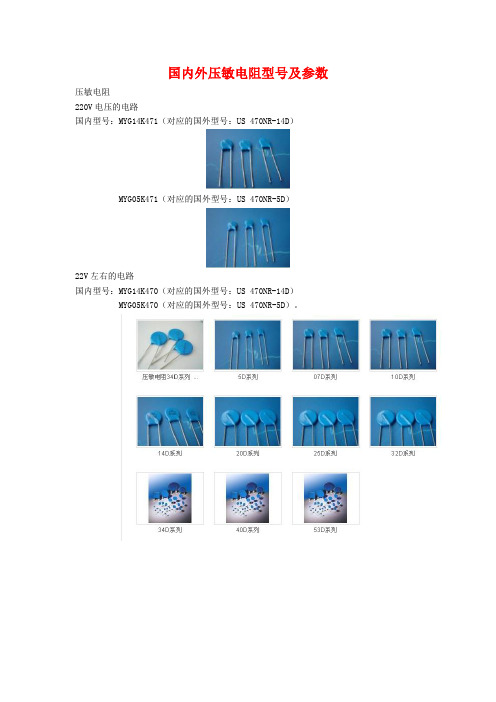
国内外压敏电阻型号及参数压敏电阻220V电压的电路国内型号:MYG14K471(对应的国外型号:US 470NR-14D)MYG05K471(对应的国外型号:US 470NR-5D)22V左右的电路国内型号:MYG14K470(对应的国外型号:US 470NR-14D)MYG05K470(对应的国外型号:US 470NR-5D)。
压敏电阻型号及参数压敏电阻百科名片压敏电阻“压敏电阻"是中国大陆的名词,意思是在一定电流电压范围内电阻值随电压而变,或者是说"电阻值对电压敏感"的阻器。
英文名称叫“Voltage Dependent Resistor”简写为“VDR”,或者叫做“Varistor"。
压敏电阻器的电阻体材料是半导体,所以它是半导体电阻器的一个品种。
现在大量使用的"氧化锌"(ZnO)压敏电阻器,它的主体材料有二价元素(Zn)和六价元素氧(O)所构成。
所以从材料的角度来看,氧化锌压敏电阻器是一种“Ⅱ-Ⅵ族氧化物半导体”。
在中国台湾,压敏电阻器称为"突波吸收器",有时也称为“电冲击(浪涌)抑制器(吸收器)”。
目录[隐藏]1、压敏电阻电路的“安全阀”作用2、压敏电阻的应用类型3、保护用压敏电阻的基本性能4. 压敏电阻的基本参数1、压敏电阻电路的“安全阀”作用2、压敏电阻的应用类型3、保护用压敏电阻的基本性能4. 压敏电阻的基本参数[编辑本段]1、压敏电阻电路的“安全阀”作用压敏电阻有什么用?压敏电阻的最大特点是当加在它上面的电压低于它的阀值" UN"时,流过它的电流极小,相当于一只关死的阀门,当电压超过UN时,流过它的电流激增,相当于阀门打开。
利用这一功能,可以抑制电路中经常出现的异常过电压,保护电路免受过电压的损害。
[编辑本段]2、压敏电阻的应用类型不同的使用场合,应用压敏电阻的目的,作用在压敏电阻上的电压/电流应力并不相同,因而对压敏电阻的要求也不相同,注意区分这种差异,对于正确使用是十分重要的。
BK3722M

驱动器接线、尺寸示意图 6. 6.驱动器接线、尺寸示意图
:mm) (单位 单位:
10mm
4mm
21mm
BK3722M
POW ALM
D6 D5 D4 D3 D2 D1 D4 D3 D2 D1
DP-2
DP-1
Hale Waihona Puke RS-2325PU+ PU5DR+ DRIN1+ IN1IN2+ IN2-
电机运转,绿灯闪烁,但伴随异常 的啸叫声
驱动器工作模式与电机不能适 配 电机负载过大 控制器或 PLC 控制过程的初速度 太大或加/减速时间太短造成的 失步
位置不准
细分数不对 控制器或 PLC 控制程序有误
“漏电”现象
驱动器、电机没有可靠接地
mm (方形 )三相 130 mm (圆形) 系列 9.BK3722M 适配电机:三相 130 130mm mm( 方形) 130mm mm( 圆形)系列
高低电压模式: ON, 驱动低压电机 OFF, 驱动高压电机
单双脉冲模式:ON, 双脉冲模式:CW/CCW OFF, 单脉冲模式:PR 脉冲信号,DR 方向信号
自动检测开关(OFF 时接收外部脉冲,ON 时驱动器内部以 30 转/分的速度运行)
2
深圳市步控机电有限公司
端口定义 针脚 号 1 RS-232 2 8 1 RX TX GND 5PU+ 标记符号 功能 接收数据 发送数据 地线 输入信号光电隔离输入正端 脉冲信号光电隔离输入负端 2 PUD5 开关为单双脉冲模式下: D5=ON 双脉冲:PU 为正向步进脉冲信号 D5=OFF 单脉冲:PU 为步进脉冲信号 3 5DR+ 方向信号光电隔离输入正端 脉冲信号光电隔离输入负端 4 DRD5 开关为单双脉冲模式下: D5=ON 双脉冲:PU 为反向步进脉冲信号 D5=OFF 单脉冲:PU 为方向控制信号 DB15 14 15 5 6 7 8 9 10 11 12 13 1、2 3 4 24PU+ 24DR+ IN1+ IN1IN2+ IN2OUT1+ OUT1OUT2+ OUT2NC L、N PE U 电源 地线 电源:AC110-220V 大地(内接驱动器外壳) 功能保留 请保持悬空 24V 脉冲信号光电隔离输入正端 24V 方向信号光电隔离输入正端 接+24V 供电电源 接+24V 供电电源 用于改变电机转向。输入电阻 220Ω,要求:低电 平 0-0.5V ,高电平 4-5V,脉冲宽度 >2.5μS 注释 接上位机串口 RX(部分型号支持) 接上位机串口 TX(部分型号支持) 接上位机串口地(部分型号支持) 接+5V 供电电源 下降沿有效,每当脉冲由高变低时电机走一步,输 入电阻 220Ω, 要求: 低电平 0-0.5V, 高电平 4-5V, 脉冲宽度>2.5μS 接+5V 供电电源
KMM372C883CK资料

元器件交易网
DRAM MODULE
ABSOLUTE MAXIMUM RATINGS *
Item Voltage on any pin relative VSS Voltage on VCC supply relative to VSS Storage Temperature Power Dissipation Short Circuit Output Current Symbol VIN, VOUT VCC Tstg PD IOS
FEATURES • Part Identification
Part number KMM372C803CK KMM372C803CS KMM372C883CK KMM372C883CS • • • • • • • • PKG SOJ TSOP SOJ TSOP 8K 4K/64ms 8K/64ms Ref. 4K CBR Ref. ROR Ref. 4K/64ms
Pins marked ′* ′ are not used in this module.
PD & ID Table
Pin PD1 PD2 PD3 PD4 PD5 PD6 PD7 PD8 ID0 50NS 1 0 1 1 0 0 0 0 0 60NS 1 0 1 1 0 1 1 0 0 0
NOTE : A12 is used for only KMM372C883CK/CS (8K Ref.)
ID1 0 PD Note :PD & ID Terminals must each be pulled up through a resistor to VCC at the next higher level assembly. PDs will be either open (NC) or driven to VSS via on-board buffer circuits. PD : 0 for Vol of Drive IC & 1 for N.C ID Note : IDs will be either open (NC) or connected directly to VSS without a buffer. ID : 0 for Vss & 1 for N.C
MK3721中文资料

Block DiagramDescriptionFeaturesThe MK3721 is ICS/MicroClock’s lowest cost, low jitter, high performance 3.3 volt VCXO designed to replace expensive VCXO modules. The on-chip Voltage Controlled Crystal Oscillator accepts a 0 to 3.3 V input voltage to cause the output clocks to vary by ±100 ppm. UsingICS/MicroClock’s patented VCXO techniques, the device uses an inexpensive external pullable crystal in the range of 16.2 - 28 MHz to produce a VCXO output clock at that same frequency. ICS/MicroClock manufactures the largest variety of Set-Top Box and multimedia clock synthesizers for all applications. If more clock outputs are needed, see the MK3732 or MK377x family of parts. Consult ICS/MicroClock to eliminateVCXOs, crystals and oscillators from your board.• Packaged in 8 pin SOIC • 3.3 V operating voltage• 16.2 MHz to 28 MHz operation • Uses an inexpensive external crystal• On-chip VCXO (patented) with pull range of 200 ppm (minimum)• VCXO tuning voltage of 0 to 3.3 V• 12 mA output drive capability at TTL levels• Advanced, low power, sub-micron CMOS process • For frequencies between 8 MHz to 16 MHz, use the MK3711A. For frequencies between 1 MHz and 8 MHz, use the MK3713. For higher than 28 MHz, use the MK3732-0516.2 -28 MHzpullable crystalVIN16.2 - 28 MHz Clock (REFOUT)Pin DescriptionsPin Assignment8 pin (150 mil) SOICMK3721X2X1GNDVDD DCVIN DCREFOUT (VCXO)Crystal SpecificationsCorrelation (load) capacitance 14 pFInitial accuracy±20 ppm maximum Drift over temperature and aging ±50 ppm maximum C0/C1 ratio 240 maximum ESR35 Ω maximumElectrical Specifications2. With a ICS/MicroClock approved pullable crystal.External ComponentsThe MK3721 requires a minimum number of external components for proper operation. A decoupling capacitor of 0.01µF should be connected between VDD and GND on pins 2 and 4, as close to theMK3721 as possible. A series termination resistor of 33 Ω may be used for the clock output. The input crystal must be connected as close to the chip as possible. The input crystal should be a parallel mode, pullable, AT cut, with 14 pF load capacitance. See previous page for crystal specifications. Consult ICS for recommended suppliers. IMPORTANT - read application note MAN05 before laying out the PCB.While the information presented herein has been checked for both accuracy and reliability, Integrated Circuit Systems Incorporated (ICS) assumes no responsibility for either its use or for the infringement of any patents or other rights of third parties, which would result from its use. No other circuits, patents, or licenses are implied. This product is intended for use in normal commercial applications. Any other applications such as those requiring extended temperature range, high reliability, or other extraordinaryenvironmental requirements are not recommended without additional processing by ICS. ICS reserves the right to change any circuitry or specifications without notice. ICS does not authorize or warrant any ICS product for use in life support devices or critical medical instruments.Ordering InformationPackage Outline and Package Dimensions(For current dimensional specifications, see JEDEC Publication No. 95.)。
MMUN2231中文资料
hFE
35 60 80 80 160 160 3.0 8.0 15 80 80 80 160 160 -
60 100 140 140 350 350 5.0 15 30 200 150 140 350 350 -
0.25 Vdc
Collector-Emitter Saturation Voltage (IC = 10 mA, IB = 0.3 mA) (I C = 10 mA, I B = 5 mA) MMUN2230/MMUN2231 (I C = 10 mA, I B = 1 mA) MMUN2215/MMUN2216/MMUN2232
WEITRON
元器件交易网
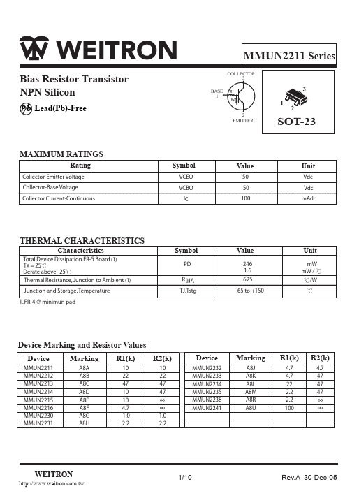
MMUN2211 Series
TYPICAL ELECTRICAL CHARACTERISTICS
MMUN2212
hFE, DC CURRENT GAIN (NORMALIZED) 1000 V CE = 10 V Cob, CAPACITANCE (pF) TA = 75 ¢J 25 ¢J -25¢J 100 3 4 f = 1 MHz lE = 0 A TA = 25 ¢J
Output Voltage (off) (VCC = 5.0 V,V B = 0.5 V ,R L = 1.0 k W) , MMUN2230 (V CC= 5.0 V VB = 0.050 V, R L = 1.0 k W ) , MMUN2215 (VCC= 5.0 V V B = 0.25 V, R L = 1.0 k W) MMUN2216 MMUN2233 MMUN2238 Input Resistor
2
1
10
1
10 IC, COLLECTOR CURRENT (mA)
- 1、下载文档前请自行甄别文档内容的完整性,平台不提供额外的编辑、内容补充、找答案等附加服务。
- 2、"仅部分预览"的文档,不可在线预览部分如存在完整性等问题,可反馈申请退款(可完整预览的文档不适用该条件!)。
- 3、如文档侵犯您的权益,请联系客服反馈,我们会尽快为您处理(人工客服工作时间:9:00-18:30)。
元器件交易网
DRAM MODULE
AC CHARACTERISTICS (0°C≤TA≤70°C, VCC=3.3V±0.3V. See notes 1,2.)
Test condition : Vih/Vil=2.0/0.8V, Voh/Vol=2.0/0.8V, Output loading CL=100pF Parameter RAS to W delay time CAS setup time(CAS-before-RAS refresh) CAS hold time(CAS-before-RAS refresh) RAS precharge to CAS hold time Access time from CAS precharge Fast page mode cycle time Fast page mode read-modify-write cycle time CAS precharge time(Fast page cycle) RAS pulse width (Fast page cycle) RAS hold time from CAS precharge W to RAS precharge time (C-B-R refresh) W to RAS hold time (C-B-R refresh) OE access time OE to data delay Output buffer turn off delay time from OE OE command hold time Present Detect Read Cycle PDE to Valid PD bit PDE to PD bit Inactive Symbol Min -5 Max Min 83 10 8 3 35 35 75 10 50 35 15 8 18 18 5 13 18 20 5 15 200K 40 80 10 60 40 15 8 71 10 8 3
-25 -5 2.4 -
ICC1* : Operating Current * (RAS, CAS, Address cycling @tRC=min) ICC2 : Standby Current (RAS=CAS=W=VIH) ICC3* : RAS Only Refresh Current * (CAS=VIH, RAS cycling @tRC=min) ICC4* : Fast Page Mode Current * (RAS=VIL, CAS cycling : tPC=min) ICC5 : Standby Current (RAS=CAS=W=Vcc-0.2V) ICC6* : CAS-Before-RAS Refresh Current * (RAS and CAS cycling @tRC=min) II(L) : Input Leakage Current (Any input 0≤VIN≤Vcc+0.3V, all other pins not under test=0 V) IO(L) : Output Leakage Current(Data Out is disabled, 0V≤VOUT≤Vcc) VOH : Output High Voltage Level (IOH = -2mA) VOL : Output Low Voltage Level (IOL = 2mA) * NOTE : ICC1, ICC3, ICC4 and ICC6 are dependent on output loading and cycle rates. Specified values are obtained with the output open. ICC is specified as an average current. In ICC1 and ICC3, address can be changed maximum once while RAS=VIL. In ICC4, address can be changed maximum once within one page mode cycle, tPC.
元器件交易网
元器件交易网
元器件交易网
DRAM MODULE
ABSOLUTE MAXIMUM RATINGS * Item Voltage on any pin relative VSS Voltage on VCC supply relative to VSS Storage Temperature Power Dissipation Short Circuit Output Current Symbol VIN, VOUT VCC Tstg PD IOS
元器件交易网
DRAM MODULE
CAPACITANCE (TA = 25°C, Vcc=3.3V, f = 1MHz) Item Input capacitance[A0-A10, B0] Input capacitance[W0, W2, OE0, OE2] Input capacitance[RAS0, RAS2] Input capacitance[CAS0, CAS4] Input/Output capacitance[DQ0 - 71] Symbol CIN1 CIN2 CIN3 CIN4 CDQ1 Min
-
Symbol VCC VSS VIH VIL
Min 3.0 0 2.0 -0.3*2
Typ 3.3 0 -
Max 3.6 0 VCC+0.3*1 0.8来自Unit V V V V
Max 990 900 100 990 900 810 720 30 990 900 25 5 0.4
Unit mA mA mA mA mA mA mA mA mA mA uA uA V V
-
KMM372V213CK/CS
Max 20 20 45 20 20 Unit pF pF pF pF pF
AC CHARACTERISTICS (0°C≤TA≤70°C, VCC=3.3V±0.3V. See notes 1,2.)
Test condition : Vih/Vil=2.0/0.8V, Voh/Vol=2.0/0.8V, Output loading CL=100pF Parameter Random read or write cycle time Read-modify-write cycle time Access time from RAS Access time from CAS Access time from column address CAS to output in Low-Z Output buffer turn-off delay Transition time(rise and fall) RAS precharge time RAS pulse width RAS hold time CAS hold time CAS pulse width RAS to CAS delay time RAS to column address delay time CAS to RAS precharge time Row address set-up time Row address hold time Column address set-up time Column address hold time Column address to RAS lead time Read command set-up time Read command hold referenced to CAS Read command hold referenced to RAS Write command hold time Write command pulse width Write command to RAS lead time Write command to CAS lead time Data set-up time Data hold time Refresh period (2K refresh) Write command set-up time CAS to W delay time Column address to W delay time CAS precharge to W delay time Symbol Min -5 Max Min 110 155 50 18 30 5 5 2 30 50 18 48 13 18 13 10 5 8 0 10 30 0 0 -2 10 10 18 13 -2 15 32 0 36 48 53 0 40 55 60 10K 32 20 10K 18 50 5 5 3 40 60 20 58 15 18 13 10 5 8 0 10 35 0 0 -2 10 10 20 15 -2 20 32 10K 40 25 10K 20 50 60 20 35 90 133 -6 Max ns ns ns ns ns ns ns ns ns ns ns ns ns ns ns ns ns ns ns ns ns ns ns ns ns ns ns ns ns ns ms ns ns ns ns 7 7 7 7 9,11 9,11 11 8 8,11 11 4,11 10,11 11 11 11 11 11 3,4 3,4,5,11 3,10,11 3,11 6,11 2 Unit Note
KMM372V213CK/CS
Rating -0.5 to +4.6 -0.5 to +4.6 -55 to +125 9 50 Unit V V °C W mA
* Permanent device damage may occur if ABSOLUTE MAXIMUM RATINGS are exceeded. Functional operation should be restricted to the conditions as detailed in the operational sections of this data sheet. Exposure to absolute maximum rating conditions for intended periods may affect device reliability. RECOMMENDED OPERATING CONDITIONS (Voltage referenced to V SS, TA = 0 to 70°C) Item Supply Voltage Ground Input High Voltage Input Low Voltage *1 : VCC+1.3V/15ns, Pulse width is measured at VCC. *2 : -1.3V/15ns, Pulse width is measured at VSS. DC AND OPERATING CHARACTERISTICS (Recommended operating conditions unless otherwise noted) Symbol ICC1 ICC2 ICC3 ICC4 ICC5 ICC6 II(L) IO(L) VOH VOL Speed -5 -6 Don′t care -5 -6 -5 -6 Don′t care -5 -6 Don′t care Don′t care KMM372V213CK/CS Min