SPS-9102AMWG中文资料
TC9102A(电话拔号IC)pdf

TC9102A (文件编号:S&CIC1035) 电话拔号IC一、 概述TC9102A 是音频/脉冲可转换的拔号器,有上次号码重拔(LNB )功能。
它采用CMOS 工艺制造,无论在音频方式还是在脉冲方式下,工作电压范围都很宽。
挂机状态下的保持电流很小。
TC9102A 采用DIP-18封装形式。
二、 特点音频/脉冲可转换的拔号电路 一个32位上次号码重拔存储器脉冲转音频(P→T )键,供PBX 使用 有闪断键最短音频持续时间为100ms 最短音频间隔时间为106ms使用3.579845MHz 晶体或陶瓷谐振器 重拔暂停时间(0ms)提供混合拔号功能有上电复位电路提供多种方式选择:拔号方式(10PPS:20PPS;音源) 续继比(40:60;30:66) 暂停时间(3.6S) 闪断功能(RESET)(P→T )等候时间(3.6S) 闪断时间(600/100ms) 闪断暂停时间(0ms)三、 引脚定义TC9102A(文件编号:S&CIC1035)电话拔号ICTC9102A(文件编号:S&CIC1035)电话拔号ICTC9102A(文件编号:S&CIC1035)电话拔号IC 四、键盘排列2、P:暂停键3、F:闪断键4、RD:重拔键5、*/P:在音频方式下,执行*;在脉冲方式下,执行暂停6、#/RD:在音频方式下,执行#;在脉冲方式下,重拔五、拔号信号选择六、极限参数(除非特殊说明:T amb=25℃,VDD=3.6V,fosc=3.579545MHz)七、电气参数(除非特殊说明,T amb=25℃,VDD=3.6V,fosc=3.579545MHz)TC9102A(文件编号:S&CIC1035)电话拔号IC2、失真(dB)=20Iog{[V12+V22+V32+…Vn2]1/2]/[(V L2+V H2)1/2]}V L,V H:行和列的信号。
V1,V2…,Vn为谐波信号(带宽=300Hz~3500Hz)TC9102A(文件编号:S&CIC1035)电话拔号IC 八、实际频率输出(fosc=3.579545MHz)九、键盘操作符号定义:a) ↑ :摘机或使免提功能工作。
Fluke 9100S和9102S手持干燥井说明书

3102-09100S-A-2569100S-B-2569100S-C-2569100S-D-256 9102S-2563102-0Published on Fluke Calibration: Europe9102S Dry-WellFor work in the temperature range of –10°C to 122°C, our Model 9102S dry-well is another first in the industry, featuring stability to ±0.05°C.This dry-well is only four inches high and six inches wide, achieves temperatures as low as –10°C, includes a NIST-traceable calibration, and is stable to ±0.05°C. The Model 9102S is excellent for dial gauges, digital thermometers, bulb switches, and other sensors that need calibration below ambient.The 9102S has two wells so you can use one for a reference thermometer to increase accuracy. Both wells are 1/2 inch in diameter, and each has inserts available for almost any sensor size. The 9102S also has a battery pack option that gives you approximately four hours of field use when AC power is unavailable.SpecificationsSpecifications9100S 9102S Range35 °C to 375 °C (95 °F to 707°F –10 °C to 122 °C (14 °F to 252 °F) at23 °C ambient Accuracy± 0.25 °C at 50 °C; ± 0.25°C at 100 °C; ± 0.5 °C at 375°C ± 0.25 °C Stability± 0.07 °C at 50 °C; ± 0.1 °C at 100 °C; ± 0.3 °C at 375 °C ± 0.05 °C Well-to-Well Uniformity± 0.2 °C with sensors of similar size at equal depths within wells Heating Times35 °C to 375 °C: 9.5 minutes ambient to 100 °C: 10minutes Stabilization5 minutes 7 minutes Cooling Times375 °C to 100 °C: 14 minutes ambient to 0 °C: 10 minutes Well Depth 102 mm (4 in);1.6 mm (1/16in) hole is 89 mm (3.5 in)deep102 mm (4 in)Removable Inserts;N/AAvailable in sizes from 1.6 mm (1/16 in) to 11.1 mm (7/16in) [6.4 mm (1/4 in) and 4.8mm (3/16 in) included]Power 115 V ac (± 10 %), 55–65Hz, 1.5 A or 230 V ac (± 10%), 0.8 A, 45–55 Hz, 175 W94-234 V ac (± 10 %), 50/60Hz, 60 W;or 12 VDC Size (HxWxD)57 x 125 x 150 mm (2.25 x 4.9 x 6.1 in)99 x 140 x 175 mm (3.9 x 5.5x 6.9 in)Weight 1 kg (2 lb 3 oz)1.8 kg (4 lb)Computer InterfaceRS-232 interfaceData at 50 °C, 100 °C, 150Data at –10 °C, 0 °C, 25 °C,9100S Users Guide (Eng) (714.29 KB)9100S Users Guide Supplement (23.76 KB)9100S Users Guide (Ger) (891.75 KB)9100S Users Guide (Rus) (665.18 KB)9102S Users Guide (English) (758.49 KB)9102S Users Guide Supplement (35.15 KB)9102S Kalibriergerät Bedienerhandbuch (German) (752.33 KB) Industrial Temperature Calibrators Workload Matrix (96.74 KB)Power and utilities industry calibration solutions (5.03 MB)Soluciones de calibración de la industria de energía y servicios (Spanish) (6.52 MB)Решения в области калибровки приборов для измерения при производстве электроэнергии иэксплуатации инженерно-технических систем (6.98 MB)Soluções de calibração do setor de serviços públicos e energia (Portuguese) (6.97 MB)Kalibrierungslösungen für die Energie- und Versorgungsindustrie (German) (5.91 MB)Solutions d'étalonnage pour le secteur de la distribution d'énergie (French) (5.9 MB)Temperature Calibration Applications and Solutions (12.87 MB)Etalonnage de la température APPLICATIONS ET SOLUTIONS (9.22 MB)Calibración de temperatura Aplicaciones y soluciones (12.7 MB)Calibração de Temperatura Aplicações e soluções (12.52 MB)Temperaturkalibrierung Anwendungen und Lösungen (12.96 MB)Best Practices for Temperature Calibration (2.13 MB)Bewährte Methoden zur Temperaturkalibrierung (German) (1.81 MB)Meilleures pratiques pour la calibration de la température (French) (1.98 MB)Mejores prácticas para la calibración de la temperatura (Spanish) (1.98 MB)Improving loop calibration temperature accuracy (991.83 KB)Verbesserung der Temperaturgenauigkeit bei der Kalibrierung von Messketten (German) (793.62 KB)Selecting an Industrial Temperature Calibrator (1.6 MB)Auswahl eines Temperaturkalibrators für den Einsatz in der Industrie (German) (1.43 MB)Sélection d'un calibrateur de température industriel (French) (1.42 MB)Selección de un calibrador de temperatura industrial (Spanish) (1.42 MB)Выбор промышленного калибратора температуры (Russian) (1.43 MB)Why calibrate temperature devices? (977.05 KB)The Development of a High-Temperature PRT Calibration Process Based on Dry-Block Calibrators (60.55 KB)Industrial Temperature Calibration Selection Guide (1.83 MB)Industrielle Temperatur-Kalibrierung Produktübersicht (German) (3.49 MB)Guide de sélection d'étalonnage industriel (French) (3.99 MB)Gúia de selección de equipos para calibraciones industriales (Spanish) (3.45 MB)Guide alla selezione di strumenti per calibrazione industriale (Italian) (3.52 MB)Указатель приборов для промышленной калибровки (Russian) (3.59 MB)©1995-2018 Fluke Corporation3102-09100S-A-2569100S-B-2569100S-C-2569100S-D-256 9102S-2563102-0。
莫莎公司 OnCell G2111 G2151I 系列工业四频GSM GPRS模块产品简介说明书

OnCell G2111/G2151I SeriesIndustrial quad-band GSM/GPRS modemsFeatures and Benefits•Quad-band GSM/GPRS850/900/1800/1900MHz•DIN-rail mounting and wall mounting•2.5kV RMS isolation for1min.for all serial signals(G2151I only)•LED indicators for GSM/GPRS and data transmission status•Extended operating temperature from-25to70°C(G2111-T only)CertificationsIntroductionThe OnCell G2111/G2151I Series of industrial quad-band GSM/GPRS modems are designed to transmit data and short messages(SMS)over GSM/ GPRS mobile networks.The modems can be used to increase the efficiency of maintenance and communication,but do not require extensive training.In addition,the modems can be mounted on a DIN rail or wall.The OnCell G2111/G2151I Series modems accept a12to48VDC power input,making them suitable for use with a variety of field power sources.The serial ports feature15kV ESD line protection to protect the products from harmful electrical discharge,and separate RS-232and RS-422/485 interfaces are built into the OnCell G2151I,each with2.5kV RMS isolation protection for one minute.The two serial interfaces on the OnCell G2151I make it ideal for attaching all kinds of devices,such as stand-alone controllers,PC COM ports,and multi-dropped electric meters.In addition,the OnCell G2111-T has an extended operating temperature(-25to70°C)design that makes it suitable for heavy industrial use. SpecificationsCellular InterfaceCellular Standards GSM,GPRSBand Options Quad-band GSM/GPRS850MHz/900MHz/1800MHz/1900MHzGPRS Multi-Slot Class10GPRS Terminal Device Class Class BGPRS Coding Schemes CS1to CS4CSD Data Rates Up to14400bpsCellular Antenna Connectors1SMA femaleNo.of SIMs1SIM Control Voltage3VSerial InterfaceNo.of Ports1Serial Standards All models:RS-232(DB9female connector)OnCell G2151I:RS-232/422/485(5-pin terminal block connector)ESD Protection OnCell G2111:15kVIsolation OnCell G2151I:2kVData Bits8Stop Bits1Parity NoneFlow Control RTS/CTSBaudrate300bps to230.4kbpsSerial SignalsRS-232TxD,RxD,RTS,CTS,DTR,DSR,DCD,RI,GNDRS-422Tx+,Tx-,Rx+,Rx-,GNDRS-485-2w Data+,Data-,GNDRS-485-4w Tx+,Tx-,Rx+,Rx-,GNDPower ParametersInput Voltage12to48VDCPower Connector Terminal blockInput Current0.625A@12VDC,0.16A@48VDCPhysical CharacteristicsHousing ABS+PolycarbonateIP Rating IP30Dimensions27x123x79mm(1.06x4.84x3.11in)Weight155g(0.34lb)Environmental LimitsOperating Temperature OnCell G2111/G2151I:-20to55°C(-4to131°F)OnCell G2111I-T:-25to70°C(-22to158°F)Storage Temperature(package included)-40to75°C(-40to167°F)Ambient Relative Humidity5to95%(non-condensing)Standards and CertificationsSafety UL60950-1EMC EN55032/24EMI CISPR32,FCC Part15B Class AEMS IEC61000-4-2ESD:Contact:4kV;Air:8kVIEC61000-4-3RS:80MHz to1GHz:3V/mIEC61000-4-4EFT:Power:0.5kVIEC61000-4-5Surge:Power:1kVIEC61000-4-6CS:3VIEC61000-4-8PFMFRadio Frequency FCC Part22H,FCC Part24E,EN301489-1,EN301489-7,EN301511MTBFTime OnCell G2111:925,000hrsOnCell G2111-T:925,000hrsOnCell G2151I:864,000hrsStandards Telcordia SR332WarrantyWarranty Period5yearsDetails See /warrantyPackage ContentsDevice1x OnCell G2111/G2151I Series GSM/GPRS modem1Antenna1x GSM/GPRSAccessory1x terminal block for power jack connectorDocumentation1x quick installation guide1x warranty cardDimensionsOrdering InformationModel Name Cellular Standard Band Operating Temp.Serial Isolation Serial StandardsOnCell G2111GSM/GPRS 850/900/1800/1900MHz-20to55°C–RS-232OnCell G2111-T GSM/GPRS 850/900/1800/1900MHz-25to70°C–RS-232OnCell G2151I GSM/GPRS 850/900/1800/1900MHz-20to55°C✓RS-232/422/4851.An activated SIM card(not included)must be provided by a third party Cellular Service Provider.Accessories(sold separately)AntennasANT-CQB-AHSM-00-3m GSM/GPRS/EDGE,omni-directional magnetic base antenna,0dBi,3m cableANT-CQB-AHSM-03-3m GSM/GPRS/EDGE,omni-directional magnetic base antenna,3dBi,3m cableANT-CQB-AHSM-05-3m GSM/GPRS/EDGE,omni-directional magnetic base antenna,5dBi,3m cableANT-CQB-ASM-01GSM/GPRS/EDGE,omni-directional rubber duck antenna,1dBiANT-WCDMA-ANF-00GSM/GPRS/EDGE/UMTS/HSPA,omni-directional outdoor antenna,0dBiANT-WCDMA-ASM-1.5GSM/GPRS/EDGE/UMTS/HSPA,omni-directional rubber duck antenna,1.5dBiANT-WCDMA-AHSM-04-2.5m GSM/GPRS/EDGE/UMTS/HSPA,omni-directional magnetic base antenna,4dBiANT-LTE-ASM-02GPRS/EDGE/UMTS/HSPA/LTE,omni-directional rubber duck antenna,2dBiANT-LTE-ANF-04GSM/GPRS/EDGE/UMTS/HSPA/LTE,omni-directional outdoor antenna,4dBi,IP66AntennasANT-LTEUS-ASM-01GSM/GPRS/EDGE/UMTS/HSPA/LTE,omni-directional rubber duck antenna,1dBiWireless Antenna CableA-CRF-SMSF-R3-100Cellular magnetic-base SMA connector with1-meter RF cable©Moxa Inc.All rights reserved.Updated Nov12,2018.This document and any portion thereof may not be reproduced or used in any manner whatsoever without the express written permission of Moxa Inc.Product specifications subject to change without notice.Visit our website for the most up-to-date product information.。
AS9102Training培训资料

02
AS9102质量管理体系 的构建与实施
Chapter
质量管理体系的基本概念与原理
质量管理体系的定义
质量管理体系的原理
基于PDCA循环、过程方法、持续改进等质量管理 原则,构建一套完整、科学、有效的管理体系。
一个组织为了实现质量目标,建立和实施的 一系列相互关联、相互协调的质量管理活动 的总和。
AS9102的应用范围和实施意义
01
AS9102适用于汽车电子控制单 元的软件开发和维护过程,包 括燃油喷射控制、点火控制、 刹车控制等系统。
02
该标准的实施有助于提高汽车 电子控制单元的可靠性、安全 性和有效性,降低汽车故障率 ,提高汽车性能和安全性。
03
同时,实施AS9102标准还有助 于提高汽车制造商的研发效率 和质量,降低开发成本和风险 。
03
AS9102质量管理体系 的审核与认证
Chapter
审核的概念和基本原理
审核的概念
审核是对某个组织或个人的管理体系、过程或产品进行客观、独立和系统的检查,以确定其是否符合相关标准 或准则的要求。
审核的基本原理
审核的基本原理包括公正性、客观性和系统性。公正性指的是审核必须由有资格的第三方进行,以确保审核的 公正性和独立性;客观性是指审核员必须以事实为依据,不偏不倚地进行审核,不受任何干扰;系统性是指审 核员必须按照规定的程序和步骤进行审核,确保审核的全面性和有效性。
AS9102标准简介
Chapter
AS9102的背景和目的
AS9102是由美国汽车工程师学会(SAE)发布的一款面向汽车电子控制单元( ECU)的软件开发和维护的标准化指导文件。
该标准旨在规定一套统一的软件开发和维护过程,以确保汽车电子控制单元的安 全性、可靠性和有效性。
SPS-9102G中文资料
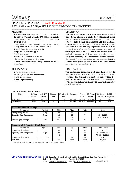
Optoway SPS-9102G**********************************************************************************************************************************************************************************************************************************************************************************************************************************************OPTOWAY TECHNOLOGY INC. No .38, Kuang Fu S. Road, Hu Kou, Hsin Chu Industrial Park, Hsin Chu, Taiwan 303Tel: 886-3-5979798 Fax: 886-3-5979737E-mail: sales@ http: // 12/1/2005 V2.01SPS-9102G / SPS-9102AG (RoHS Compliant)3.3V / 1310 nm / 2.5 Gbps SFP LC SINGLE-MODE TRANSCEIVER**********************************************************************************************************************************************************************FEATURESl Hot-Pluggable SFP Footprint LC Optical Transceiver l Small Form-Factor Pluggable (SFP) MSA compatible l Compliant with Intra-Office SONET OC-48 SR / SDH STM-16 (I-16)l Compliant with Fibre Channel 1x/2x SM-LC-L FC-PI l Compliant with IEEE 802.3z 1000BASE-LX l AC/AC Coupling according to MSA l Single +3.3 V Power Supply l RoHS Compliantl -10 to 85o C Operation: SPS-9102G l -40 to 85o C Operation: SPS-9102AGl Class 1 Laser International Safety Standard IEC-60825 CompliantAPPLICATIONSl ATM Switches and Routersl SONET / SDH Switch Infrastructure l XDSL Applications l Metro Edge SwitchingDESCRIPTIONThe SPS-9102G series single mode transceivers is small form factor pluggable module for bi-directional serial optical data communications such as SONET OC-48 / SDH STM-16 (I-16), Gigabit Ethernet 1000BASE-LX and Fibre Channel 1x/2x SM-LC-L FC-PI. It is with the SFP 20-pin connector to allow hot plug capability. This module is designed for single mode fiber and operates at a nominal wavelength of 1310 nm. The transmitter section uses a multiple quantum well laser and is a class 1 laser compliant according to International Safety Standard IEC-60825. The receiver section uses an integrated InGaAs detector preamplifier (IDP) mounted in an optical header and a limiting post-amplifier IC.LASER SAFETYThis single mode transceiver is a Class 1 laser product. It complies with IEC-60825 and FDA 21 CFR 1040.10 and 1040.11. The transceiver must be operated within the specified temperature and voltage limits. The optical ports of the module shall be terminated with an optical connector or with a dust plug.ORDER INFORMATIONP/No.Bit Rate (Gb/s) SONET /SDH Distance (km) Wavelength (nm) Package Temp. (oC) TX Power (dBm) RX Sens. (dBm) RoHSCompliant SPS-9102G 2.488 SR/I-16 2 1310 LC SFP -10 to 85 -3 to -9.5 -18 Yes SPS-9102AG2.488SR/I-162 1310 LC SFP -40 to 85 -3 to -9.5 -18 YesAbsolute Maximum RatingsParameterSymbol Min Max Units NotesStorage TemperatureTstg -40 85 o COperating Case Temperature Topr -10 -40 85 85 o C SPS-9102G SPS-9102AGPower Supply VoltageVcc-0.53.6VRecommended Operating ConditionsParameterSymbol Min Typ Max Units / NotesPower Supply VoltageVcc 3.1 3.3 3.5 V Operating Case Temperature Topr -10 -40 85 85 oC / SPS-9102G oC / SPS-9102AGPower Supply Current I CC (TX+RX)200 300 mA Data Rate62224882670Mb/s / 11. OC-48, Gigabit Ethernet and 1x/2x Fibre Channel compliant.Transmitter Specifications (-10o C < Topr < 85o C, 3.1V < Vcc < 3.5V)Parameter Symbol Min Typ Max Units NotesOpticalOptical Transmit Power Po -9.5 --- -3 dBm 1Output Center Wavelength λ1270 1310 1350 nmOutput Spectrum Width ∆λ--- --- 3 nm RMS (σ)Extinction Ratio E R8.2 --- --- dBOutput Eye Compliant with Telecordia GR-253-GORE and ITU-T Recommendation G.957Optical Rise Time t r150 ps 20 % to 80% Values Optical Fall Time t f150 ps 20 % to 80% Values Relative Intensity Noise RIN -120 dB/HzElectricalData Input Current – Low I IL-350 µAData Input Current – High I IH350 µADifferential Input Voltage V IH - V IL0.5 2.4 V Peak-to-PeakTX Disable Input Voltage – Low T DIS, L0 0.5 V 2TX Disable Input Voltage – High T DIS, H 2.0 Vcc V 2TX Disable Assert Time T ASSERT10 µsTX Disable Deassert Time T DEASSERT 1 msTX Fault Output Voltage -- Low T FaultL0 0.5 V 3TX Fault Output Voltage -- High T FaultH 2.0 Vcc+0.3 V 31. Output power is power coupled into a 9/125 µm single mode fiber.2. There is an internal 4.7K to 10K ohm pull-up resistor to VccTX.3. Open collector compatible,4.7K to 10K ohm pull-up to Vcc (Host Supply Voltage).Receiver Specifications(-10o C < Topr < 85o C, 3.1V < Vcc < 3.5V)Parameter Symbol Min Typ Max Units NotesOpticalSensitivity Sens -18 dBm 4,5 Maximum Input Power Pin -3 dBm 4,5Signal Detect -- Asserted Pa --- -18 dBm Transition: low to high Signal Detect -- Deasserted Pd -30 --- --- dBm Transition: high to low Signal detect -- Hysteresis 1.0 --- dBWavelength of Operation 1100 --- 1600 nmElectricalDifferential Output Voltage V OH– V OL0.6 2.0 VOutput LOS Voltage -- Low V OL0 0.5 V 6Output LOS Voltage -- High V OH 2.0 Vcc+0.3 V 64. Measured at 223-1 PRBS at BER 1E-10 @ 1300 nm.5. Measured at 27-1 PRBS at BER 1E-12 @ 1300 nm for 2.125 Gb/s, 1.25Gb/s, and 1.063 Gb/s.6. Open collector compatible, 4.7K to 10K ohm pull-up to Vcc (Host Supply Voltage).*********************************************************************************************************************************************************************** OPTOWAY TECHNOLOGY INC. No.38, Kuang Fu S. Road, Hu Kou, Hsin Chu Industrial Park, Hsin Chu, Taiwan 303Tel: 886-3-5979798 Fax: 886-3-5979737***********************************************************************************************************************************************************************OPTOWAY TECHNOLOGY INC. No .38, Kuang Fu S. Road, Hu Kou, Hsin Chu Industrial Park, Hsin Chu, Taiwan 303Tel: 886-3-5979798 Fax: 886-3-5979737PINSignal NameDescriptionPINSignal Name Description1 TX GND Transmitter Ground11 RX GND Receiver Ground2 TX Fault Transmitter Fault Indication12 RX DATA OUT- Inverse Receiver Data Out 3 TX Disable Transmitter Disable (Module disables on high or open)13 RX DATA OUT+ Receiver Data Out 4 MOD-DFE2 Modulation Definition 2 – Two wires serial ID Interface14 RX GND Receiver Ground5 MOD-DEF1 Modulation Definition 1 – Two wires serial ID Interface15 Vcc RX Receiver Power – 3.3V ±5% 6 MOD-DEF0 Modulation Definition 0 – Ground in Module16 Vcc TX Transmitter Power – 3.3V ±5% 7 N/C Not Connected 17 TX GNDTransmitter Ground 8 LOS Loss of Signal 18 TX DATA IN+ Transmitter Data In9 RX GND Receiver Ground 19 TX DATA IN- Inverse Transmitter Data In 10RX GNDReceiver Ground20TX GNDTransmitter GroundModule DefinitionModule DefinitionMOD-DEF2 PIN 4 MOD-DEF1 PIN 5 MOD-DEF0 PIN 6 Interpretation by Host 4SDASCLLV-TTL LowSerial module definitionprotocolModule Definition 4 specifies a serial definition protocol. For this definition, upon power up, MOD-DEF(1:2) appear as no connector (NC) and MOD-DEF(0) is TTL LOW. When the host system detects this condition, it activates the serial protocol. The protocol uses the 2-wire serial CMOS E 2PROM protocol of the ATMEL AT24C01A/02/04 family of components.*********************************************************************************************************************************************************************** OPTOWAY TECHNOLOGY INC. No.38, Kuang Fu S. Road, Hu Kou, Hsin Chu Industrial Park, Hsin Chu, Taiwan 303Tel: 886-3-5979798 Fax: 886-3-5979737。
SIWAREX WP231工程说明书
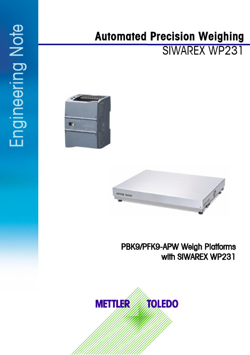
Automated Precision WeighingSIWAREX WP231E n g i n e e r i n g N o t ePBK9/PFK9-APW Weigh Platformswith SIWAREX WP2312E n g i n e e r i n g N o t eInhaltsverzeichnis1.1 Field of application ....................................................................................... 32.1 Connecting to Siwarex WP231 ...................................................................... 4 2.2 Configuring Siwarex WP231 ......................................................................... 5 2.3Configuring PBK9/PFK9 Weigh Platform ......................................................... 5 2.3.1 Connecting the weighing sensor to a PC ................................................................... 5 2.3.2 RS422/485 interface .............................................................................................. 5 2.3.3 Weight output ........................................................................................................ 6 2.3.4 User mode ............................................................................................................ 6 2.4 Weight transmission with Siwatool ................................................................. 6 4.1 Other Applicable Documents .......................................................................... 8 4.2 Figures . (8)1Introduction1.1Field of applicationPBK9/PFK9-APW weigh platforms from METTLER TOLEDO (hereafter referred to as “weighing sen-sors”)were developed especially for operation in automated plants. The weighing sensors profides an optionfor direct connection to the SIWAREX WP231 weighing system by Siemens (hereafter referred to as "Si-warex"). This document describes the steps for commissioning and optimizing this kind of connection.Figure 1: Connection to Siwarex via RS48534E n g i n e e r i n g N o t e2 CommissioningThis chapter summarizes, in form of a list, the steps required for commissioning PBK9/PFK9-APW weigh platforms at Siwarex.2.1 Connecting to Siwarex WP231The following diagram shows the connection of the PBK9/PFK9-APW weigh platforms to Siwarex WP231.Figure 2: Connection diagrammAssignment of the connections at SIWAREX WP231for the connection with PBK9/PFK9-APW weigh plat-form:2.2Configuring Siwarex WP231The following sections describe the steps required to configure the Siwarex when using Siwatool PCSoftware. Service mode must be activated before the records can be sent from Siwatool to the Siwarex:service commands-> Service Mode ON. When the service mode is activated, the corresponding icon(open-end wrench on red background) appears in the status bar.For SIWAREX WP231 as of firmware V3.0.4, parameters in the data record 3 and 13 must be adjustedas follows:DR3:Weight unit: grLoading cell type: Digital load cell Mettler Toledo PBKMaximum weight: capacity of the weighing sensor (unit: gr)Calibration weight 0: 0Calibration weight 1: capacity of the weighing sensor (unit: gr)Calibration weight 2: 0Calibration digits 0 (measured): 0Calibration digits 1 (measured): (capacity of the weighing sensor (unit: gr)) / (resolution)e.g.: 1 kg / 0.1 g = 1000 gr / 0.1 gr = 10,000Calibration digits 2 (measured): 0DR13:RS485 Protocol: Mettler Toledo PBK/PFK9 (Code 4)RS485 Baudrate: 38400RS485 Parity: evenRS485 Data Bits: 7RS485 Stop Bits: 1Delay: 2000 ms2.3Configuring PBK9/PFK9 Weigh PlatformThe steps are described below to configure the weighing sensor such that it operates with Siwarex.2.3.1Connecting the weighing sensor to a PCThe RS232 interface of the weighing sensor should be connected to a PC (using APW-Link TM - Free Con-figuration Tool – /apw-link) via the SubD9 connector of the ConBlock. The interface pa-rameters are configured in factory settings as follows: 9,600 baud, 8 data bits, no parity and1 stop bit.These settings shall NOT be modified.2.3.2RS422/485 interfaceFor the weighing platform, following parameters need to be configured:Parameter Value DescriptionM103 1 2 Configure the communication interface of the weighing platform as "RS485mode (half-duplex)"COM 1 8 0 0 Configure the communication interface of the weighing platform as follows:▪38400 bits per second▪7 data bits / even parity / 1 stop bit▪No handshakeM68 0 Keep the parameters of the communication interface permanently stored,such that they are not reset to factory defaults after a power cycle56E n g i n e e r i n g N o t e2.3.3 Weight outputFor seamless communication with the Siwarex, the update rate must be configured as follows:Update rate (UPD): UPD 922.3.4 User modeThe weighing sensors are automatically set to zero at power on. This might be undesirable in certain applications, particularly for larger platforms when a weight value shall be recovered after power off. When selecting the mode described below, the weight values refer to a fix reference point (as per pro-duction setting) and the zeroing at start up is disabled.Start-up with fix reference point: M35 12.4 Weight transmission with SiwatoolAfter successfully configuring the Siwarex and the weighing sensor, Siwatool can be used to weigh forcontrol purposes.The "Start Send" command (code 905) is used to send the individual records to the Siwarex. To con-firm, a record with “Receive” can be read out from the Siwarex. The communication can be stopped with the "Stop Send" command (code 906).Below in the picture, you can see the overview of the SIWATOOL:Figure 3: Siwatool(1) Control elements for SIWATOOL and the for the operation of the weighing sensor (2) Parameter list of the SIWATOOL module (3) Offline values of the SIWATOOL module(4) Online values of the connected SIWAREX module3Supported METTLER TOLEDO ProductsFTAV9.5.2WMS/WMSPBK9-APW/PBK9PFK9-APW/PFK9SLF6/SLF67Mettler-Toledo GmbH IndustrialCH-8606 Nänikon, SwitzerlandSubject to technical changes© 03/2017 Mettler-Toledo GmbHPrinted in Switzerland EN181_160407 4 Appendix4.1 Other Applicable Documents[1] METTLER TOLEDO, Reference Manual, Standard Interface Command Set (11781363G)[2] METTLER TOLEDO, Installation Manual PBK9 bench scales (30233012A)[3] METTLER TOLEDO, Installation Manual PFK9 floor scales (30233015A)[4]Siemens, Siwarex WP231, Device Manual, version 06/2014 (or later)4.2 FiguresFigure 1: Connection to Siwarex via RS485.................................. 3 Figure 2: Connection diagramm .................................................. 4 Figure 3: Siwatool (6)。
Transition Networks SISTG1040-2x2-LRT 产品说明书

SISTG1040-2x2-LRT Quick Start GuideIntroductionTransition Networks’ SISTG1040-242-LRT and SISTG1040--282-LRT are Industrial Unmanaged GbESwitches suitable for industrial Ethernet applications. See the SISTG1040-2x2-LRT Install Guide forimportant Cautions, Warnings, Features, Specifications, Front & Back Panel, LEDs, RESET button,Installation, Package Contents, and Troubleshooting, Warranty, Support & Compliance information.Unpack and Install1.Check package contents: verify that you have received the Switch, Quick Start Guide, Terminal Block, and Mountingkit. Two optional Power Supply models are available (sold separately).2.Unpack the contents in install location, and continue with Desktop, DIN Rail, or Wall mounting; see the Install Guide.3.Review the front panel description the Install Guide. Use the front panel grounding screw as required; see chapter 3of the Install Guide.4.Install SFP modules. Refer to the specific SFP manual for cautions and warnings. Note: The SFP ports should use ULListed Optional Transceiver product, Rated 3.3Vdc, Laser Class 1.5.Connect to Network / Devices: the switches provide eight or four 10M/100M/1G RJ45 ports. Use Cat 5e or betterunshielded twisted pair (UTP) cable terminated with an RJ-45 connector.6.Connect to 12-48V DC Power. Caution: Before applying power from an AC outlet, insert terminal connectors into theSISTG1040-2x2-LRT switch and verify all connections. Plugging in power connection after energizing power supply(s) may damage the switch. a) Connect the wires between the +P1 and –P1 terminals on the switch terminal block and the +V and -V terminals on the power supply. Optionally, connect the wires between the +P2 and –P2 terminals on the switch terminal block and the +V and -V terminals on the power supply if redundant power is to be used.b) Use a small Phillips screwdriver to tighten the wire-clamp screws. c) Connect the three wires (e.g., green, black,white) of the power cord to the Ground (), N, and L clamp connections respectively. Use a small Phillipsscrewdriver to tighten the wire-clamp screws. d) Connect the plug end of the power cord into a live AC outlet.e) Verify that the Power Supply front panel DC OK LED is lit. See the Install Guide for more details.7.Check the SYS LED. If it is lit, the power connection is correct. If not, see the Install Guide.LED Descriptions: three front panel LEDs allow switch status checking and monitoring:•Power LEDs indicate if the switch is powered up correctly.•System LED indicates if the system is ready.•Port Status LEDs indicates the current status of each port. Check these LEDs to understand the port status.RESET ButtonPress the RESET button to reboot the switch. The front panel LEDs flash and the switch is reset.Front PanelsSISTG1040-242-LRT SISTG1040-282-LRT LED SummaryLED Color FunctionSYS (System) Green On = the switch is ready. Of = the switch is not ready.P1 (Power 1) Green Input Power source 1 supplying power. P2 (Power 2) Green Input Power source 2 supplying power.Link/Act/Speed Green/AmberLight off: port disconnected or link failed.Green Light on: 1G Link Present, No Activity.Amber Light on: 100M/10M Link Present, No Activity.Green Blinking: 1G Activity. Port is sending or receiving data.Amber Blinking: 100M/10M Activity. Port is sending or receiving data.Link/Act/Speed Green/AmberLNK: Amber/Green (Two Color)Light off: port disconnected or link failedAmber Light on: link-up (100M)Green Light on: link-up (1G)Blinking: activity (receiving or transmitting data)Contact UsFor Transition Networks Drivers, Firmware, etc. go to the Product Support webpage (logon required).For Manuals, Application Notes, Brochures, Data Sheets, Specifications, etc. go to the Support Library (no logon required).Transition Networks | 10900 Red Circle Drive | Minnetonka, MN 55343, U.S.A.Technical Support: Technical support is available 24-hours a day. US and Canada: 1-800-260-1312;International: 00-1-952-941-7600. | tel: +1.952.941.7600 | toll free: 1.800.526.9267 | fax: 952.941.2322 ******************** | ************************** | ******************************。
9102操作说明

安規校正器9102使用手冊版本1.32007年3月料號 A11 000831法律事項聲明本使用手冊內容如有變更,恕不另行通知。
本公司並不對本使用手冊之適售性、適合作某種特殊用途之使用或其他任何事項作任何明示、暗示或其他形式之保證或擔保。
故本公司將不對手冊內容之錯誤,或因增減、展示或以其他方法使用本手冊所造成之直接、間接、突發性或繼續性之損害負任何責任。
致茂電子股份有限公司台灣省桃園縣龜山鄉華亞科技園區華亞一路66號版權聲明:著作人―致茂電子股份有限公司―西元2003-2007年,版權所有,翻印必究。
未經本公司同意或依著作權法之規定准許,不得重製、節錄或翻譯本使用手冊之任何內容。
ii保證書致茂電子股份有限公司秉持〝品質第一是責任,客戶滿意是榮譽〞之信念,對所製造及銷售之產品自交貨日起一年內,保證正常使用下產生故障或損壞,負責免費修復。
保證期間內,對於下列情形之一者,本公司不負免費修復責任,本公司於修復後依維修情況酌收費用:(1) 非本公司或本公司正式授權代理商直接銷售之產品。
(2) 因不可抗拒之災變,或可歸責於使用者未遵照操作手冊規定使用或使用人之過失,如操作不當或其他處置造成故障或損壞。
(3) 非經本公司同意,擅自拆卸修理或自行改裝或加裝附屬品,造成故障或損壞。
保證期間內,故障或損壞之維修品,使用者應負責運送到本公司或本公司指定之地點,其送達之費用由使用者負擔。
修復完畢後運交使用者(限臺灣地區)或其指定地點(限臺灣地區)之費用由本公司負擔。
運送期間之保險由使用者自行向保險公司投保。
致茂電子股份有限公司桃園縣333龜山鄉華亞科技園區華亞一路66號服務專線:(03)327-9999傳真電話:(03)327-2886網址:iii設備及材料污染控制聲明本產品之有毒有害物質或元素表:有毒有害物質或元素部件名稱鉛汞鎘六价鉻多溴聯苯多溴聯苯醚Pb Hg Cd Cr6+ PBB PBDE PCBA °○○○○○機殻°○○○○○標準配件°○○○○○包裝材料○○○○○○○:表示該有毒有害物質在該部件所有均質材料中的含量在SJ/T 11363-2006與EU 2005/618/EC規定的限量要求以下。
- 1、下载文档前请自行甄别文档内容的完整性,平台不提供额外的编辑、内容补充、找答案等附加服务。
- 2、"仅部分预览"的文档,不可在线预览部分如存在完整性等问题,可反馈申请退款(可完整预览的文档不适用该条件!)。
- 3、如文档侵犯您的权益,请联系客服反馈,我们会尽快为您处理(人工客服工作时间:9:00-18:30)。
Optoway SPS-9102MWG**********************************************************************************************************************************************************************************************************************************************************************************************************************************************OPTOWAY TECHNOLOGY INC. No .38, Kuang Fu S. Road, Hu Kou, Hsin Chu Industrial Park, Hsin Chu, Taiwan 303Tel: 886-3-5979798 Fax: 886-3-597973712/1/2005 V2.0 1SPS-9102MWG / SPS-9102AMWG (RoHS Compliant)3.3V / 1310 nm / Multirate Digital Diagnostic SFP LC SINGLE-MODE TRANSCEIVER **********************************************************************************************************************************************************************FEATURESl Hot-Pluggable SFP Footprint LC Optical Transceiver l Small Form-Factor Pluggable (SFP) MSA compatible l Up to 2.67 Gb/s bi-directional data linksl Compliant with Intra-Office SONET OC-48 SR / SDH STM-16 (I-16)l Compliant with Fibre Channel 1X/2X SM-LC-L FC-PI l Compliant with IEEE 802.3z 1000BASE-LX l SFF-8472 Digital Diagnostic Function l AC/AC Coupling according to MSA l Single +3.3 V Power Supply l RoHS Compliantl -10 to 85o C Operation: SPS-9102MWG l -40 to 85o C Operation: SPS-9102AMWGl Class 1 Laser International Safety Standard IEC-60825 CompliantAPPLICATIONSl SONET OC-48 SR / SDH STM-16 I-16 l SONET OC-12 / SDH STM-4 l SONET OC-3 / SDH STM-1l Gigabit Ethernet / 1X/2X Fibre ChannelDESCRIPTIONThe SPS-9102MWG series single mode transceivers is small form factor pluggable module for bi-directional serial optical data communications such as SONET OC-48 / SDH STM-16 (I-16), Gigabit Ethernet 1000BASE-LX and Fibre Channel 1x/2x SM-LC-L FC-PI. It is with the SFP 20-pin connector to allow hot plug capability. Digital diagnostic functions are available via an I 2C. This module is designed for single mode fiber and operates at a nominal wavelength of 1310 nm. The transmitter section uses a multiple quantum well laser and is a class 1 laser compliant according to International Safety Standard IEC-60825. The receiver section uses an integrated InGaAs detector preamplifier (IDP) mounted in an optical header and a limiting post-amplifier IC.LASER SAFETYThis single mode transceiver is a Class 1 laser product. It complies with IEC-60825 and FDA 21 CFR 1040.10 and 1040.11. The transceiver must be operated within the specified temperature and voltage limits. The optical ports of the module shall be terminated with an optical connector or with a dust plug.ORDER INFORMATIONP/No.Bit Rate(Mb/s)SONET /SDHDistance (km) Wavelength (nm)PackageTemp. (o C) TX Power (dBm) RX Sens. (dBm) RoHS CompliantSPS-9102MWGMultirate*SR / I-16 2 1310 LC SFP with DMI -10 to 85 -3 to -9.5 -18 Yes SPS-9102AMWG Multirate*SR / I-1621310LC SFP with DMI -40 to 85-3 to -9.5-18YesMultirate*: 2.67 Gb/s / OC-48 / 2X FC / GbE / 1X FC / OC-12 / OC-3Absolute Maximum RatingsParameterSymbol Min Max Units NotesStorage TemperatureTstg -40 85 o COperating Case Temperature Topr -10 -40 85 85 o C SPS-9102MWG SPS-9102AMWG Power Supply VoltageVcc-0.53.6VRecommended Operating ConditionsParameterSymbol Min Typ Max Units / NotesPower Supply VoltageVcc 3.1 3.3 3.5 VOperating Case Temperature Topr -10 -40 85 85 oC / SPS-9102MWG oC / SPS-9102AMWGPower Supply Current I CC (TX+RX)200 300 mA Data Rate12524882670Mb/sTransmitter Specifications (-10o C < Topr < 85o C, 3.1V < Vcc < 3.5V)Parameter Symbol Min Typ Max Units NotesOpticalOptical Transmit Power Po -9.5 --- -3 dBm 1Output Center Wavelength λ1270 1310 1350 nmOutput Spectrum Width ∆λ--- --- 3 nm RMS (σ)Extinction Ratio E R8.2 --- --- dBOutput Eye Compliant with Telecordia GR-253-GORE and ITU-T Recommendation G.957Optical Rise Time t r150 ps 20 % to 80% Values Optical Fall Time t f150 ps 20 % to 80% Values Relative Intensity Noise RIN -120 dB/HzElectricalData Input Current – Low I IL-350 µAData Input Current – High I IH350 µADifferential Input Voltage V IH - V IL0.5 2.4 V Peak-to-PeakTX Disable Input Voltage – Low T DIS, L0 0.5 V 2TX Disable Input Voltage – High T DIS, H 2.0 Vcc V 2TX Disable Assert Time T_off10 µsTX Disable Negate Time T_on 1 msTX Fault Output Voltage -- Low T FaultL0 0.5 V 3TX Fault Output Voltage -- High T FaultH 2.0 Vcc+0.3 V 31. Output power is power coupled into a 9/125 µm single mode fiber.2. There is an internal 4.7K to 10K ohm pull-up resistor to VccTX.3. Open collector compatible,4.7K to 10K ohm pull-up to Vcc (Host Supply Voltage).Receiver Specifications(-10o C < Topr < 85o C, 3.1V < Vcc < 3.5V)Parameter Symbol Min Typ Max Units NotesOpticalSensitivity @ OC-48Sens1 -3 -18 dBm 4 Sensitivity @2X Fibre Channal Sens2 -3 -19 dBm 5 Sensitivity @Gigabit Ethernet Sens3 -3 -20 dBm 5 Sensitivity @OC-12 Sens4 -3 -22 dBm 4 Sensitivity @OC-3 Sens5 -10 -22 dBm 4Signal Detect -- Asserted Pa --- -18 dBm Transition: low to high Signal Detect -- Deasserted Pd -33 --- --- dBm Transition: high to low Signal detect -- Hysteresis 1.0 --- dBWavelength of Operation 1100 --- 1600 nmElectricalDifferential Output Voltage V OH– V OL0.6 2.0 VOutput LOS Voltage -- Low V OL0 0.5 V 6Output LOS Voltage -- High V OH 2.0 Vcc+0.3 V 6LOS Assert Time T_loss_on100 µsLOS Deassert Time T_loss_off100 µs4. Measured at 2-1 PRBS at BER 1E-10 @ 1300 nm.5. Measured at 27-1 PRBS at BER 1E-12 @1300nm.6. Open collector compatible, 4.7K to 10K ohm pull-up to Vcc (Host Supply Voltage).*********************************************************************************************************************************************************************** OPTOWAY TECHNOLOGY INC. No.38, Kuang Fu S. Road, Hu Kou, Hsin Chu Industrial Park, Hsin Chu, Taiwan 303***********************************************************************************************************************************************************************OPTOWAY TECHNOLOGY INC. No .38, Kuang Fu S. Road, Hu Kou, Hsin Chu Industrial Park, Hsin Chu, Taiwan 303PINSignal NameDescriptionPINSignal Name Description1 TX GND Transmitter Ground11 RX GND Receiver Ground2 TX Fault Transmitter Fault Indication12 RX DATA OUT- Inverse Receiver Data Out 3 TX Disable Transmitter Disable (Module disables on high or open)13 RX DATA OUT+ Receiver Data Out 4 MOD-DFE2 Modulation Definition 2 – Two wires serial ID Interface14 RX GND Receiver Ground5 MOD-DEF1 Modulation Definition 1 – Two wires serial ID Interface15 Vcc RX Receiver Power – 3.3V ±5% 6 MOD-DEF0 Modulation Definition 0 – Ground in Module16 Vcc TX Transmitter Power – 3.3V ±5% 7 N/C Not Connected 17 TX GNDTransmitter Ground 8 LOS Loss of Signal 18 TX DATA IN+ Transmitter Data In9 RX GND Receiver Ground 19 TX DATA IN- Inverse Transmitter Data In 10RX GNDReceiver Ground20TX GNDTransmitter GroundModule DefinitionModule DefinitionMOD-DEF2 PIN 4 MOD-DEF1 PIN 5 MOD-DEF0 PIN 6 Interpretation by Host 4SDASCLLV-TTL LowSerial module definitionprotocolModule Definition 4 specifies a serial definition protocol. For this definition, upon power up, MOD-DEF(1:2) appear as no connector (NC) and MOD-DEF(0) is TTL LOW. When the host system detects this condition, it activates the serial protocol. The protocol uses the 2-wire serial CMOS E 2PROM protocol of the ATMEL AT24C01A/02/04 family of components.*********************************************************************************************************************************************************************** OPTOWAY TECHNOLOGY INC. No.38, Kuang Fu S. Road, Hu Kou, Hsin Chu Industrial Park, Hsin Chu, Taiwan 303。