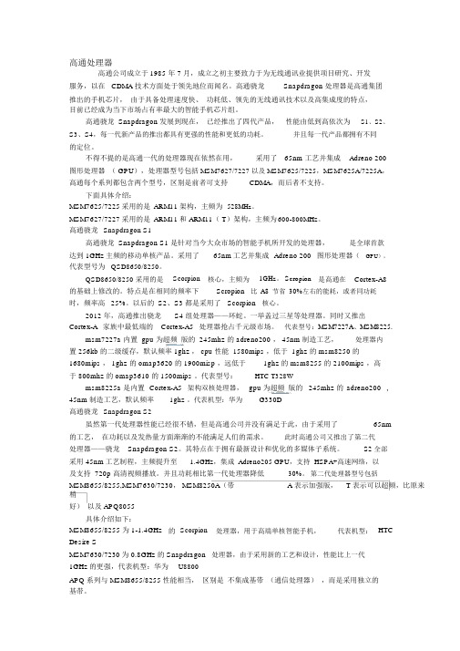
AD860PM
ASM860固晶机操作说明书
AD860自动固晶机操作指导书1. 对三点一线(镜头.吸嘴.顶针.):首先选择一颗芯片,用鼠标选择设定→焊头与顶针→焊头→卸下吸嘴帽→吸晶高度→按鼠标左键→看镜头、吸嘴、顶针中心点是否在十字架同一直线上,调整完成后,装上吸嘴帽。
2. 做PR及测间距:进入设定→点击选择晶片→放如扩好的晶片→点击开始教读→灯光调整后→点击下一页→使用滑鼠选择晶片框大小→点击确认→选择教读→选是开始自动校正→自动测间距→搜寻范围→要按照晶片大小来调整,即完成。
3. 吸晶与固晶高度调整:进入设定→选择焊头/顶针→点击焊头→吸晶高度→点击自动→自动完成后再加10~20个数字,即完成。
进入设定→选择焊头/顶针→点击焊头→固晶高度→点击自动→自动完成后再加10~20个数字,即完成。
4. 调整顶真高度:进入设定→选择焊头/顶针→点击顶针→顶针上升高度→点击+—调整→按上下键观察顶针高度,取一个蓝光双电极芯片高度,且顶针要与十字线重合,即完成。
5.上胶与胶量调整:将胶盘锁紧螺丝,进入设定→点击点胶→选择预备点胶将点胶臂摆出胶盘,加胶进胶盘后调好刮胶厚度,返回→选择点胶头→吸胶高度→上下键观察点胶针接触胶盘底部后再加1~10个数字,即完成取胶设定。
返回→选择点胶头→点胶高度→上下键观察点胶针接触胶盘底部后再加1~10个数字,即完成取胶设定。
6.支架/PCB编程:进入设定→点击料架设定→料架编号→选择1→移到第一个料架PCB第一个点移到镜头下→点击确定→选择2→第2个料架PCB第一个点移到镜头下→点击确定,即完成。
进入设定→点击PCB设定→设定模式→矩阵→输入一个料架上有几块PCB→2行→2列→然后用摇杆→移到第一个料架上PCB的左上角→确定→第二点移到第二块PCB的左上角→第三点移到第三块PCB的左上角→点击接受→教读对点→对点数量→对两个点→对一小块 PCB 的对角→开始教读→灯光调整→开始校正→教读对点完成。
→搜寻范围→要按照对点图形来调整。
DC2798A 60V双相单输出同步升压控制器带PMBus演示说明书
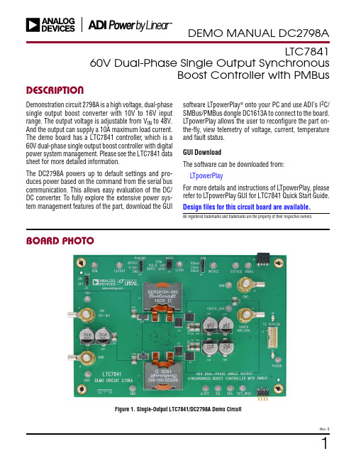
1Rev. 0DESCRIPTIONLTC784160V Dual-Phase Single Output SynchronousBoost Controller with PMBusDemonstration circuit 2798A is a high voltage, dual-phase single output boost converter with 10V to 16V input range. The output voltage is adjustable from V IN to 48V. And the output can supply a 10A maximum load current. The demo board has a LTC7841 controller , which is a 60V dual-phase single output boost controller with digital power system management. Please see the LTC7841 data sheet for more detailed information.The DC2798A powers up to default settings and pro-duces power based on the command from the serial bus communication. This allows easy evaluation of the DC/DC converter . To fully explore the extensive power sys-tem management features of the part, download the GUIAll registered trademarks and trademarks are the property of their respective owners.BOARD PHOTOsoftware L TpowerPlay ® onto your PC and use ADI’s I 2C/SMBus/PMBus dongle DC1613A to connect to the board. L TpowerPlay allows the user to reconfigure the part on-the-fly, view telemetry of voltage, current, temperature and fault status.GUI DownloadThe software can be downloaded from: L TpowerPlayFor more details and instructions of L TpowerPlay, please refer to L TpowerPlay GUI for LTC7841 Quick Start Guide.Design files for this circuit board are available .Figure 1. Single-Output LTC7841/DC2798A Demo Circuit2DEMO MANUAL DC2798ARev. 0QUICK START PROCEDUREDemonstration circuit DC2798A is easy to set up to evalu-ate the performance of the LTC7841. Refer to Figure 2 for the proper measurement equipment set-up and follow the procedure below.1. With power off, connect the input power supply to V IN (10V to 16V) and GND (input return).2. Connect the 48V output load between V OUT0 and GND (Initial load: No Load).3. Connect the DVMs to the input and outputs. Set default jumper position: JP1: 100mV (ILIM); JP2: FLOAT; JP3: CCM; JP4: ON.4. Connect the dongle to DC2798A and turn on the input power supply.5. Follow the L TpowerPlay Quick Start Procedure section to set the proper output voltage.6. Once the proper output voltages are established, adjust the loads within the operating range and ob-serve the output voltage regulation, ripple voltage and other parameters.NOTE: When measuring the output or input voltage rip-ple, do not use the long ground lead on the oscilloscope probe. See Figure 3 for the proper scope probe technique. Short, stiff leads need to be soldered to the (+) and (–) terminals of an output capacitor . The probe’s ground ring needs to touch the (–) lead and the probe tip needs to touch the (+) lead.PERFORMANCE SUMMARYSpecifications are at T A = 25°CPARAMETER CONDITIONSMIN TYPMAX UNITSInput Voltage Range 1016V Output Voltage, V OUTV IN = 10V to 16V, I OUT = 0A to 10A 1648 (Default)V Maximum Output Current, I OUT V IN = 10V to 16V, V OUT = 16V to 48V 10A Typical EfficiencyV IN =12V, V OUT = 48V, I OUT = 10A 97.4 (See Figure 5)%Default Switching Frequency150kHzFigure 2. Proper Measurement Equipment Set-Up3DEMO MANUAL DC2798ARev. 0QUICK START PROCEDUREFigure 3. Measuring Output Voltage RippleFigure 4. Demo Set-Up with PCConnecting a PC to DC2798AYou can use a PC to configure the power management features of the LTC7841 such as: nominal V OUT , marginset points, ON/OFF control. The DC1613A dongle may be plugged when V IN is present.4DEMO MANUAL DC2798A Rev. 0QUICK START PROCEDUREFigure 5. Efficiency vs Load Current at V IN = 12V, f S = 150kHz, V OUT = 48VFigure 6. V OUT Load T ransient Response at V IN = 12V, V OUT = 48V Figure 7. V OUT Voltage Ripple at V IN = 12V, V OUT = 48V, I OUT = 10ALOAD CURRENT (A)E FF I C I E N C Y(%)10091999795939896949290dc2798a F05104826200μs/DIVV OUT 20MHz BW 100mV/DIV0A TO 2.5A LOAD STEP5μs/DIVV OUT 20MHz BW 200mV/DIVFigure 8. Thermal at V IN = 12V, V OUT = 48V, I OUT = 10A, T A = 25°C, No Airflow5DEMO MANUAL DC2798ARev. 0LTPOWERPLAY SOFTWARE GUIFigure 9. L TpowerPlay Main InterfaceL TpowerPlay is a powerful Windows-based development environment that supports Analog Devices power sys-tem management ICs and μModules, including LTM4675, LTM4676, LTM4677, LTM4678, LTM4680, LTM4700, LTM4664, LTC3880, LTC3882, LTC3883, LTC3884, LTC7880 and LTC7841. The software supports a variety of different tasks. You can use L TpowerPlay to evaluate Analog Devices ICs by connecting to a demo board sys-tem. L TpowerPlay provides unprecedented diagnostic and debug features. It becomes a valuable diagnostic tool dur-ing board bring-up to program or tweak the power man-agement scheme in a system, or to diagnose power issues when bringing up rails. L TpowerPlay utilizes the DC1613A USB-to-SMBus controller to communicate with one ofmany potential targets, including LTM4675, LTM4676, LTM4677, LTM4678, LTM4680, LTM4700, LTM4664, LTC3880, LTC3882, LTC3883, LTC3884, LTC7880 and LTC7841’s demo system, or a customer board. The soft-ware also provides an automatic update feature to keep the software current with the latest set of device drivers and documentation. The LTpowerPlay software can be downloaded from: L TpowerPlayTo access technical support documents for L TC Digital Power Products visit the L TpowerPlay Help menu. Online help also available through the LTpowerPlay.6DEMO MANUAL DC2798A Rev. 0LTPOWERPLAY QUICK START PROCEDUREThe following procedure describes how to use L TpowerPlay to monitor and change the settings of LTC7841.1. Download and install the L TPowerPlay GUI: L TpowerPlay2. Launch the L TpowerPlay GUI.a. The GUI should automatically identify the DC2798A. The system tree on the left hand side should look like this:b. A green message box shows for a few seconds in the lower left-hand corner, confirming that LTC7841 is communicating:c. Writing to the MFR_VOUT_COMMAND register via the PMBus allows the adjustment of the V OUT reference from 0% to 100% of the maximum reference of 2.4V. With current demo board setting (R193 = 191k, and R194 = 10k), the V FB /V OUT ratio is about 1/20. Follow Equation 1 to get the correct V OUT . V OUT = 20 • MFR_VOUT_COMMAND (%) • 2.4 (1) If you want to set the output voltage to be 48V. In the Config tab, type in 99.8 in the MFR_VOUT_COMMAND_LTC7841 box, like this:Then, click the “W” (PC to RAM) icon to write these register values to the LTC7841. After finishing this step, the V OUT internal reference voltage is set to ~2.4V.If the write is successful, you will see the following message:7DEMO MANUAL DC2798ARev. 0LTPOWERPLAY QUICK START PROCEDUREd. If you want to set the output voltage to be 24V. In the Config tab, type in 50 in the MFR_VOUT_COMMAND_L TC7841 box. Then the V OUT internal reference voltage is set to ~1.2V.e. In order to turn on the power stage, click the “Apply an operation to all devices” iconf. In the popup “Apply an operation to all devices” dialog box, click the “On” button to turn on the power stageg. After the test, in the popup “Apply an operation to all devices” dialog box, click the “Immediate Off” button to turn off the power stage.8DEMO MANUAL DC2798A Rev. 0PARTS LISTITEM QTY REFERENCE PART DESCRIPTIONMANUFACTURER/PART NUMBER Required Circuit Components14C1, C85-C87CAP ., 470µF, ALUM POL Y HYB, 25V, 20%, 10x10.2mm, G, SMD, RADIAL, AEC-Q200PANASONIC, EEHZK1E471P 23C3, C105, C120CAP ., 4.7µF, X5R, 25V, 10%, 0603MURATA, GRM188R61E475KE15D 32C9, C23CAP ., 0.22µF, X7R, 25V, 10%, 0603MURATA, GRM188R71E224KA88D 410C10-C12, C24-C26, C88, C93, C122, C123CAP ., 10µF, X7R, 63V, 10%, 1210SAMSUNG, CL32B106KMVNNWE 52C13, C28CAP ., 0.01µF, X7R, 16V, 10%, 0603AVX, 0603YC103KAT2A 61C18CAP ., 0.01µF, X7R, 25V, 10%, 0603, AEC-Q200AVX, 06033C103K4Z2A 71C20CAP ., 100pF, C0G/NP0, 50V, 5%, 0603AVX, 06035A101JAT2A 82C71, C77CAP ., 1000pF, C0G, 100V, 5%, 0805TDK, C2012C0G2A102J060AA 94C94, C95, C115, C116CAP ., 22µF, X7R, 25V, 10%, 1210SAMSUNG, CL32B226KAJNNNE 101C104CAP ., 470pF, X7R, 50V, 10%, 0603AVX, 06035C471KAT2A 112C106, C117CAP ., 0.1µF, X7R, 100V, 10%, 0603AVX, 06031C104KAT2A128C107-C114CAP ., 68µF, ALUM POL Y HYB, 63V, 20%, 10x10.2mm, G, SMD, RADIAL, AEC-Q200PANASONIC, EEHZC1J680P 131C118CAP ., 120pF, C0G/NPO, 100V, 5%, 0603AVX, 06031A121JAT2A141C119CAP ., 1000pF, X7R, 16V, 10%, 0603WURTH ELEKTRONIK, 885012206034151C121CAP ., 390pF, COG/NPO, 50V, 5%, 0603AVX, 06035A391JAT2A 161C124CAP ., 2.2µF, X7S, 16V, 10%, 0603, AEC-Q200TDK, CGA3E1X7S1C225K080AC 172C125, C126CAP ., 1µF, X7S, 100V, 10%, 0805MURATA, GRJ21BC72A105KE11L 182D1, D2DIODE, SCHOTTKY, 100V, 1A, POWERDI-123DIODES INC., DFLS1100-7191D5DIODE, ZENER, 6.8V, 400mW, SOD-323NEXPERIA, PDZ6.8B, 115202L1, L2IND., 6.8µH, POWER SHIELDED WIREWOUND, 10%, 30A, 0.00205Ω, 27.9mm x 27.94mmCOILCRAFT , SER2915H-682KL 214Q1, Q2, Q5, Q6XSTR., MOSFET , N-CH, 60V, 64A, PG-TDSON-8INFINEON, BSC065N06LS5224Q3, Q4, Q7, Q8XSTR., MOSFET , N-CH, 60V, 100A, PG-TDSON-8INFINEON, BSC027N06LS5233R13, R15, R194RES., 10k, 1%, 1/10W, 0603VISHAY, CRCW060310K0FKEC 242R14, R37RES., 0.002Ω, 1%, 3W, 2512, METAL, SENSE, AEC-Q200PANASONIC, ERJMS4SF2M0U 252R21, R44RES., 100Ω, 1%, 1/10W, 0603, AEC-Q200PANASONIC, ERJ3EKF1000V 262R90, R92RES., 1.0Ω, 5%, 1/2W, 0805PANASONIC, ERJ6DQJ1R0V 271R183RES., 5.1k, 1%, 1/10W, 0603, AEC-Q200NIC, NRC06F5101TRF 281R185RES., 470k, 1%, 210mW, 0805, NTC THERMISTOR, AEC-Q200VISHAY, NTCS0805E3474FXT293R192, R198, R199RES., 100k, 1%, 1/10W, 0603, AEC-Q200VISHAY, CRCW0603100KFKEA 301R193RES., 191k, 1%, 1/10W, 0603VISHAY, CRCW0603191KFKEA 311R200RES., 30k, 1%, 1/10W, 0603, AEC-Q200KOA SPEER, RK73H1JTTD3002F 321R201RES., 38.3k, 1%, 1/10W, 0603, AEC-Q200NIC, NRC06F3832TRF 331R202RES., 150k, 1%, 1/10W, 0603PANASONIC, ERJ3EKF1503V341U1IC, POWER CONTROLLER, QFN-36 (5x6)ANALOG DEVICES., LTC7841EUHE#PBF9DEMO MANUAL DC2798ARev. 0PARTS LISTITEM QTY REFERENCE PART DESCRIPTIONMANUFACTURER/PART NUMBER Additional Demo Board Circuit Components11C5CAP ., 0.1µF, X7R, 50V, 10%, 0603AVX, 06035C104KAT2A20C19, C35CAP ., OPTION, 060331D3LED, GREEN, WATERCLEAR, 1206WURTH ELEKTRONIK, 150120GS7500041D4LED, RED, WATERCLEAR, 1206WURTH ELEKTRONIK, 150120RS7500050D6DIODE, OPTION, SCHOTTKY, POWERDI 12361Q9XSTR., MOSFET N-CH, 60V, 300mA, SOT-23VISHAY, 2N7002K-T1-GE371Q10XSTR., MOSFET , P-CH, 20V, 5.9A, TO-236 (SOT23-3)VISHAY, Si2365EDS-T1-GE380R11, R19, R20, R42, R47, R187, R196RES., OPTION, 060398R12, R17, R22, R38, R43, R184, R186, R188RES., 0Ω, 1/10W, 0603, AEC-Q200VISHAY, CRCW06030000Z0EA 102R16, R197RES., 4.99k, 1%, 1/10W, 0603PANASONIC, ERJ3EKF4991V 111R27RES., 200Ω, 1%, 1/10W, 0603VISHAY, CRCW0603200RFKEA 121R28RES., 127Ω, 1%, 1/10W, 0603, AEC-Q200NIC, NRC06F1270TRF 131U2IC, MEMORY, EEPROM, 2Kb (256x8), TSSOP-8, 400kHz MICROCHIP , 24LC025-I/STHardware For Demo Board Only116E1-E7, E10, E15, E22, E37-E40, E42, E44TEST POINT , TURRET , 0.094" MTG. HOLE, PCB 0.062" THK MILL-MAX, 2501-2-00-80-00-00-07-024J1-J4EVAL BOARD STUD HARDWARE SET , #10-32ANALOG DEVICES, 720-001031J5CONN., HDR, SHROUDED, MALE, 2×6, 2mm, VERT , ST , THT FCI, 98414-G06-12ULF41J6CONN., HDR, FEMALE, 2×4, 2mm, R/A THT SULLINS CONNECTOR SOLUTIONS,NPPN042FJFN-RC 51J7CONN., HDR, MALE, 2×4, 2mm, R/A THT MOLEX, 87760-081662JP1, JP2CONN., HDR, MALE, 1×4, 2mm, VERT , ST , THT SAMTEC, TMM-104-02-L-S 71JP3CONN., HDR., MALE, 2×3, 2mm, VERT , ST , THT WURTH ELEKTRONIK, 6200062112181JP4CONN., HDR, MALE, 1×3, 2mm, VERT , ST , THT WURTH ELEKTRONIK, 6200031112194MP1-MP4STANDOFF , NYLON, SNAP-ON, 0.625 (5/8"), 15.9mm KEYSTONE, 8834104XJP2, XJP7-XJP9CONN., SHUNT , FEMALE, 2-POS, 2mmSAMTEC, 2SN-BK-G10DEMO MANUAL DC2798ARev. 0SCHEMATIC DIAGRAM11DEMO MANUAL DC2798ARev. 0Information furnished by Analog Devices is believed to be accurate and reliable. However , no responsibility is assumed by Analog Devices for its use, nor for any infringements of patents or other rights of third parties that may result from its use. Specifications subject to change without notice. No license is granted by implication or otherwise under any patent or patent rights of Analog Devices.SCHEMATIC DIAGRAM12DEMO MANUAL DC2798ARev. 0ANALOG DEVICES, INC. 202003/20ESD CautionESD (electrostatic discharge) sensitive device. Charged devices and circuit boards can discharge without detection. Although this product features patented or proprietary protection circuitry, damage may occur on devices subjected to high energy ESD. Therefore, proper ESD precautions should be taken to avoid performance degradation or loss of functionality.Legal Terms and ConditionsBy using the evaluation board discussed herein (together with any tools, components documentation or support materials, the “Evaluation Board”), you are agreeing to be bound by the terms and conditions set forth below (“Agreement”) unless you have purchased the Evaluation Board, in which case the Analog Devices Standard Terms and Conditions of Sale shall govern. Do not use the Evaluation Board until you have read and agreed to the Agreement. Your use of the Evaluation Board shall signify your acceptance of the Agreement. This Agreement is made by and between you (“Customer”) and Analog Devices, Inc. (“ADI”), with its principal place of business at One Technology Way, Norwood, MA 02062, USA. Subject to the terms and conditions of the Agreement, ADI hereby grants to Customer a free, limited, personal, temporary, non-exclusive, non-sublicensable, non-transferable license to use the Evaluation Board FOR EVALUATION PURPOSES ONL Y. Customer understands and agrees that the Evaluation Board is provided for the sole and exclusive purpose referenced above, and agrees not to use the Evaluation Board for any other purpose. Furthermore, the license granted is expressly made subject to the following additional limitations: Customer shall not (i) rent, lease, display, sell, transfer , assign, sublicense, or distribute the Evaluation Board; and (ii) permit any Third Party to access the Evaluation Board. As used herein, the term “Third Party” includes any entity other than ADI, Customer , their employees, affiliates and in-house consultants. The Evaluation Board is NOT sold to Customer; all rights not expressly granted herein, including ownership of the Evaluation Board, are reserved by ADI. CONFIDENTIALITY. This Agreement and the Evaluation Board shall all be considered the confidential and proprietary information of ADI. Customer may not disclose or transfer any portion of the Evaluation Board to any other party for any reason. Upon discontinuation of use of the Evaluation Board or termination of this Agreement, Customer agrees to promptly return the Evaluation Board to ADI. ADDITIONAL RESTRICTIONS. Customer may not disassemble, decompile or reverse engineer chips on the Evaluation Board. Customer shall inform ADI of any occurred damages or any modifications or alterations it makes to the Evaluation Board, including but not limited to soldering or any other activity that affects the material content of the Evaluation Board. Modifications to the Evaluation Board must comply with applicable law, including but not limited to the RoHS Directive. TERMINATION. ADI may terminate this Agreement at any time upon giving written notice to Customer . Customer agrees to return to ADI the Evaluation Board at that time. LIMITATION OF LIABILITY. THE EVALUATION BOARD PROVIDED HEREUNDER IS PROVIDED “AS IS” AND ADI MAKES NO WARRANTIES OR REPRESENTATIONS OF ANY KIND WITH RESPECT TO IT . ADI SPECIFICALL Y DISCLAIMS ANY REPRESENTATIONS, ENDORSEMENTS, GUARANTEES, OR WARRANTIES, EXPRESS OR IMPLIED, RELATED TO THE EVALUATION BOARD INCLUDING, BUT NOT LIMITED TO, THE IMPLIED WARRANTY OF MERCHANTABILITY, TITLE, FITNESS FOR A PARTICULAR PURPOSE OR NONINFRINGEMENT OF INTELLECTUAL PROPERTY RIGHTS. IN NO EVENT WILL ADI AND ITS LICENSORS BE LIABLE FOR ANY INCIDENTAL, SPECIAL, INDIRECT , OR CONSEQUENTIAL DAMAGES RESUL TING FROM CUSTOMER’S POSSESSION OR USE OF THE EVALUATION BOARD, INCLUDING BUT NOT LIMITED TO LOST PROFITS, DELAY COSTS, LABOR COSTS OR LOSS OF GOODWILL. ADI’S TOTAL LIABILITY FROM ANY AND ALL CAUSES SHALL BE LIMITED TO THE AMOUNT OF ONE HUNDRED US DOLLARS ($100.00). EXPORT . Customer agrees that it will not directly or indirectly export the Evaluation Board to another country, and that it will comply with all applicable United States federal laws and regulations relating to exports. GOVERNING LAW . This Agreement shall be governed by and construed in accordance with the substantive laws of the Commonwealth of Massachusetts (excluding conflict of law rules). Any legal action regarding this Agreement will be heard in the state or federal courts having jurisdiction in Suffolk County, Massachusetts, and Customer hereby submits to the personal jurisdiction and venue of such courts. The United Nations Convention on Contracts for the International Sale of Goods shall not apply to this Agreement and is expressly disclaimed.。
Firstack PM140 数字智能型 IGBT 驱动产品说明书
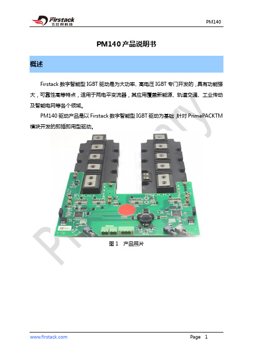
PM140产品说明书概述Firstack数字智能型IGBT驱动是为大功率、高电压IGBT专门开发的,具有功能强大,可靠性高等特点,适用于两电平变流器,其应用覆盖新能源、轨道交通、工业传动及智能电网等各个领域。
PM140驱动产品是以Firstack数字智能型IGBT驱动为基础,针对PrimePACKTM 模块开发的即插即用型驱动。
图1 产品照片目录概述 (1)系统框架图 (3)使用步骤及注意事项 (4)机械尺寸图 (5)引脚定义 (6)状态指示灯说明 (8)驱动参数 (9)主要功能说明 (12)◆短路保护 (12)◆欠压保护 (12)◆软关断 (13)◆温度保护及采样 (13)门极电阻位置指示 (17)订购信息 (19)技术支持 (19)法律免责声明 (19)联系方式 (19)系统框架图数字控制核1D Z1V CC1V EE1软关断电路信号输入1C1级G1级V CC1E1级数字控制核2D Z2V CC2V EE2软关断电路信号输入2C2级G2级V CC2E2级COM1COM2故障指示==V CC1V EE1COM1故障指示电源输入V CE 检测电源检测V CE 检测电源检测故障返回电源V CC2V EE2COM2图2 系统框架图使用步骤及注意事项驱动器简便使用的相关步骤如下:1. 选择合适的驱动器使用驱动器时,应注意该驱动器适配的IGBT模块型号。
对于非指定IGBT 模块无效,使用不当可能会导致驱动和模块失效。
2. 将驱动器安装到IGBT 模块上对IGBT模块或驱动器的任何处理都应遵循国际标准IEC 60747-1第Ⅸ章或欧洲标准EN 100015要求的静电敏感器件保护的一般规范(即工作场所、工具等必须符合这些标准)。
如果忽视这些规范,IGBT和驱动器都可能会损坏。
3. 将驱动器连接到控制单元将驱动器接插件(光纤)连接到控制单元,并为驱动器提供合适的供电电压4. 检查驱动器功能检查门极电压:对于关断状态,额定门极电压在相应的数据手册中给出,对于导通状态,该电压为15V。
AD860全自动固晶机操作规程
AD860全自动固晶机操作规程第一章总则为确保AD860全自动固晶机的安全运行和产品质量,制定本操作规程。
本规程适用于厂内AD860全自动固晶机的操作人员。
第二章操作前的准备工作2.1检查设备的运行状态,确认设备处于正常工作状态。
2.2检查设备的供电线路,确保电源正常,并按照规定接地。
2.3检查设备的工作环境,确保周围环境干燥、无尘、无腐蚀性气体,温度适宜。
2.4检查设备的工作台面,确保表面平整,无杂物。
2.5检查设备上的刀具和夹具,确保刀具锐利,夹具牢固。
第三章操作流程3.1打开设备电源,待设备启动完成后进入操作界面。
3.2选择适合的程序,点击“开始”按钮,开始设备的自动运行。
操作人员应立即退到安全区域等待设备完成。
3.3检查设备的运行状态,注意观察设备的操作过程,确保固晶过程顺利进行。
3.4根据固晶产品的要求,调整设备的参数,例如温度、压力等。
3.5监控设备的运行情况,及时处理设备出现的异常情况,如报警、挤压不均匀等。
3.6当设备完成固晶过程后,设备将自动停止运行。
操作人员应确认固晶结果是否符合要求。
第四章操作要点4.1操作时,操作人员应穿戴符合要求的工作服、手套、安全鞋等个人防护装备。
4.2在固晶产品表面接触时,应使用清洁、无油污的工具,避免污染产品表面。
4.3操作人员离开操作区域时,应将设备设为暂停状态或关闭设备电源。
4.4若发现设备出现异常情况或故障,操作人员应立即停止设备运行,并向维修人员报告。
第五章安全注意事项5.1禁止未经培训的人员操作设备。
5.2禁止将手指、头发等物体靠近设备运动部件。
避免发生意外伤害。
5.3禁止吸烟、饮食等行为,严禁在工作区内进行非工作相关活动。
5.4严禁在设备运行中擅自调整参数、清洁设备或触摸设备内部部件。
5.5使用设备过程中,应遵守设备使用规范,不得滥用设备或进行不适当的操作。
第六章紧急情况处理6.1发生设备异常情况时,操作人员应立即停止设备运行,并按照应急处理程序处理。
手机主流CPU解析
高通处理器高通公司成立于1985 年 7 月,成立之初主要致力于为无线通讯业提供项目研究、开发服务,以在CDMA 技术方面处于领先地位而闻名。
高通骁龙Snapdragon 处理器是高通集团推出的手机芯片,由于具备处理速度快、功耗低、领先的无线通讯技术以及高集成度的特点,目前已经成为当下市场占有率最大的智能手机芯片组。
高通骁龙 Snapdragon 发展到现在,已经推出了四代产品,性能由低到高依次为S1、S2、S3、S4,每一代新产品的推出都具有更强的性能和更低的功耗。
并且每一代产品都拥有不同的定位。
不得不提的是高通一代的处理器现在依然在用,采用了65nm 工艺并集成Adreno 200图形处理器( GPU),处理器型号包括MSM7627/7227以及 MSM7625/7225,MSM7625A/7225A,高通每个系列都包含两个型号,区别是前者可支持CDMA,而后者不支持。
下面具体介绍:MSM7625/7225采用的是ARM11架构,主频为528MHz。
MSM7627/7227采用的是ARM11和 ARM11( T)架构,主频为600-800MHz。
高通骁龙Snapdragon S1高通骁龙 Snapdragon S1 是针对当今大众市场的智能手机所开发的处理器,是全球首款达到 1GHz主频的移动单核产品。
采用了65nm工艺并集成Adreno 200图形处理器(GPU),代表型号为QSD8650/8250。
QSD8650/8250 采用的是Scorpion核心,主频为1GHz。
Scropion是高通在Cortex-A8的基础上修改的。
特点是在相同的频率下Scropion比A8节省30%左右的能耗,或者同功耗时,频率高25%。
以后的S2、S3 都是采用了Scorpion核心。
2012 年,高通推出骁龙S4 组处理器——环蛇。
一举盖过三星等处理器。
同时又推出Cortex-A家族中最低端的Cortex-A5处理器抢占千元级市场。
易用Logic PM2220电力表说明书
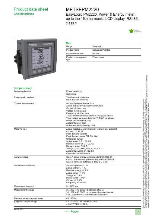
T h e i n f o r m a t i o n p r o v i d e d i n t h i s d o c u m e n t a t i o n c o n t a i n s g e n e r a l d e s c r i p t i o n s a n d /o r t e c h n i c a l c h a r a c t e r i s t i c s o f t h e p e r f o r m a n c e o f t h e p r o d u c t s c o n t a i n e d h e r e i n .T h i s d o c u m e n t a t i o n i s n o t i n t e n d e d a s a s u b s t i t u t e f o r a n d i s n o t t o b e u s e d f o r d e t e r m i n i n g s u i t a b i l i t y o r r e l i a b i l i t y o f t h e s e p r o d u c t s f o r s p e c i f i c u s e r a p p l i c a t i o n s .I t i s t h e d u t y o f a n y s u c h u s e r o r i n t e g r a t o r t o p e r f o r m t h e a p p r o p r i a t e a n d c o m p l e t e r i s k a n a l y s i s , e v a l u a t i o n a n d t e s t i n g o f t h e p r o d u c t s w i t h r e s p e c t t o t h e r e l e v a n t s p e c i f i c a p p l i c a t i o n o r u s e t h e r e o f .N e i t h e r S c h n e i d e r E l e c t r i c I n d u s t r i e s S A S n o r a n y o f i t s a f f i l i a t e s o r s u b s i d i a r i e s s h a l l b e r e s p o n s i b l e o r l i a b l e f o r m i s u s e o f t h e i n f o r m a t i o n c o n t a i n e d h e r e i n .Product data sheetCharacteristicsMETSEPM2220EasyLogic PM2220, Power & Energy meter,up to the 15th harmonic, LCD display, RS485,class 1MainRange EasyLogic Product name EasyLogic PM2200Device short name PM2220Product or component typePower meterComplementaryDevice application Power monitoring Sub billingPower quality analysis Total harmonic distortion Up to the 15th harmonicType of measurementApparent power min/max, totalActive and reactive power min/max, total Current min/max, avg Voltage min/max, avg Frequency min/max, avgTotal current harmonic distortion THD (I) per phase Total voltage harmonic distortion THD (U) per phase Power factor min/max, avg Apparent energy totalActive and reactive energy totalMetering typeActive, reactive, apparent energy (signed, four quadrant)Current I, I1, I2, I3Peak demand currentsPeak demand power PM, QM, SM Unbalance currentActive power P, P1, P2, P3Reactive power Q, Q1, Q2, Q3Demand power P, Q, SVoltage U, U21, U32, U13, V, V1, V2, V3Apparent power S, S1, S2, S3Calculated neutral currentAccuracy classClass 1 active energy conforming to IEC 62053-21Class 1 reactive energy conforming to IEC 62053-24Class 5 harmonic distorsion (I THD & U THD)Measurement accuracyApparent power +/- 1 %Active energy +/- 1 %Reactive energy +/- 1 %Active power +/- 1 %Voltage +/- 0.5 %Power factor +/- 0.01Current +/- 0.5 %Frequency +/- 0.05 %Measurement current 5…6000 mAMeasurement voltage35…480 V AC 50/60 Hz between phases20…277 V AC 50/60 Hz between phase and neutral 480…999000 V AC 50/60 Hz with external VT Frequency measurement range 45…65 Hz[Us] rated supply voltage44...277 V AC 45...65 Hz +/- 10 %44...277 V DC +/- 10 %Network frequency50 Hz60 HzRide-through time100 Ms 120 V AC typical400 Ms 230 V AC typical50 ms 125 V DC typicalLine Rated Current1 A5 AMaximum power consumption in VA6 VA 277 V ACMaximum power consumption in W 3.3 W (power lines (AC))2 W at 277 V (power lines (DC))Input impedance Current (impedance <= 0.3 mOhm)Voltage (impedance > 5 MOhm)Tamperproof of settings Protected by access codeDisplay type Backlit LCDDisplay colour MonochromeDisplay resolution128 x 128 pixelsDemand intervals Configurable from 1 to 60 minInformation displayed Demand current (past value)Demand current (present value)Demand power (past value)Demand power (present value)VoltageCurrentFrequencyEnergy consumptionHarmonic distortionPower factorActive powerApparent powerReactive powerUnbalanced in %Harmonic amplitudeControl type 4 x buttonLocal signalling Red LED: output signal 1...9999000 pulse/ k_h (kWh, kVAh, kVARh)Green LED: module operation and integrated communicationNumber of inputs0Number of outputs0Communication port protocol Modbus RTU 4800 bps, 9600 bps, 19200 bps, 38.4 Kbps even/odd or none - 2wires 2500 VCommunication port support Screw terminal block: RS485Data recording Time stampingMin/max for 8 parametersFunction available Real time clockSampling rate64 samples/cycleCybersecurity Enable/disable communication portsCommunication service Remote monitoringLanguage SpanishFrenchEnglishRussianPortugueseGermanChineseProduct certifications CE IEC 61010-1CULus UL 61010-1CULus conforming to CSA C22.2 No 61010-1RCMEACC-TickMounting mode Clip-onMounting position VerticalMounting support FrameworkProvided equipment 1 x Installation guideMeasurement category Category III 480 VCategory II 480…600 VElectrical insulation class Double insulationClass IIFlame retardance V-0 conforming to UL 94Connections - terminals Current transformer screw connection bottom) 6Voltage inputs screw connection top) 4Material PolycarbonateWidth 3.78 in (96 mm)Depth Total 3.00 in (76.09 mm)Embedded 2.43 in (61.64 mm)Height 3.78 in (96 mm)Net Weight10.58 oz (300 g)Compatibility code PM2220EnvironmentService life7 year(s)IP degree of protection IP54 front: conforming to IEC 60529Body IP30 IEC 60529Relative humidity5…95 % 122 °F (50 °C)Pollution degree2Ambient air temperature for operation14…140 °F (-10…60 °C)Ambient air temperature for storage-13…158 °F (-25…70 °C)Operating altitude<= 6561.68 ft (2000 m)Electromagnetic compatibility Electrostatic discharge conforming to IEC 61000-4-2Radiated radio-frequency electromagnetic field immunity test IEC 61000-4-3Electrical fast transient/burst immunity test conforming to IEC 61000-4-4Surge immunity test IEC 61000-4-5Conducted RF disturbances conforming to IEC 61000-4-6Magnetic field at power frequency conforming to IEC 61000-4-8Voltage dips and interruptions immunity test IEC 61000-4-11Emission tests conforming to FCC part 15 class AOvervoltage category IIIOrdering and shipping detailsGTIN03606480800177Nbr. of units in pkg.1Package weight(Lbs)9.52 oz (270 g)Packing UnitsUnit Type of Package 1PCEPackage 1 Height 3.78 in (9.6 cm)Package 1 width 2.65 in (6.72 cm)Package 1 Length 4.00 in (10.16 cm)Unit Type of Package 2BB1Number of Units in Package 21Package 2 Weight12.80 oz (363 g)Package 2 Height 4.53 in (11.5 cm)Package 2 width 3.43 in (8.7 cm)Package 2 Length 4.72 in (12 cm)Unit Type of Package 3S03Number of Units in Package 318Package 3 Weight15.48 lb(US) (7.02 kg)Package 3 Height11.81 in (30 cm)Package 3 width11.81 in (30 cm)Package 3 Length15.75 in (40 cm)Offer SustainabilitySustainable offer status Green Premium productREACh Regulation REACh DeclarationEU RoHS Directive Compliant EU RoHS DeclarationMercury free YesRoHS exemption information YesChina RoHS Regulation China RoHS Declaration Circularity Profile End Of Life Information。
MSI B460M PRO 产品说明书
1ContentsContentsSafety Information ...........................................................................................2Specifications ...................................................................................................3Rear I/O Panel .................................................................................................7LAN Port LED Status Table . (7)Overview of Components (8)CPU Socket .................................................................................................................9DIMM Slots................................................................................................................10PCI_E1~3: PCIe Expansion Slots ..............................................................................10JFP1, JFP2: Front Panel Connectors .......................................................................11JAUD1: Front Audio Connector ................................................................................11SATA1~6: SATA 6Gb/s Connectors ...........................................................................12M2_1: M.2 Slot (Key M) .............................................................................................12ATX_PWR1, CPU_PWR1: Power Connectors ...........................................................13JUSB1~2: USB 2.0 Connectors .................................................................................14JUSB3: USB 3.2 Gen 1 5Gbps Connector .................................................................14CPU_FAN1, SYS_FAN1: Fan Connectors .................................................................15JTPM1: TPM Module Connector ...............................................................................15JCI1: Chassis Intrusion Connector ...........................................................................16JCOM1: Serial Port Connector .................................................................................16JBAT1: Clear CMOS (Reset BIOS) Jumper ...............................................................17JRAINBOW1: Addressable RGB LED connector ......................................................17JRGB1: RGB LED connector .....................................................................................18EZ Debug LED ...........................................................................................................18UEFI BIOS . (19)BIOS Setup ................................................................................................................20Entering BIOS Setup .................................................................................................20Resetting BIOS ..........................................................................................................20Updating BIOS...........................................................................................................21Installing OS, Drivers & Utilities . (22)Installing Windows ® 10..............................................................................................22Installing Drivers ......................................................................................................22Installing Utilities .. (22)Thank you for purchasing the MSI ® B460M PRO/ B460M-A PRO motherboard. This User Guide gives information about board layout, component overview, BIOS setup and software installation.Safety Information∙The components included in this package are prone to damage from electrostatic discharge (ESD). Please adhere to the following instructions to ensure successful computer assembly.∙Ensure that all components are securely connected. Loose connections may cause the computer to not recognize a component or fail to start.∙Hold the motherboard by the edges to avoid touching sensitive components. ∙It is recommended to wear an electrostatic discharge (ESD) wrist strap when handling the motherboard to prevent electrostatic damage. If an ESD wrist strap is not available, discharge yourself of static electricity by touching another metal object before handling the motherboard.∙Store the motherboard in an electrostatic shielding container or on an anti-static pad whenever the motherboard is not installed.∙Before turning on the computer, ensure that there are no loose screws or metal components on the motherboard or anywhere within the computer case.∙Do not boot the computer before installation is completed. This could cause permanent damage to the components as well as injury to the user.∙If you need help during any installation step, please consult a certified computer technician.∙Always turn off the power supply and unplug the power cord from the power outlet before installing or removing any computer component.∙Keep this user guide for future reference.∙Keep this motherboard away from humidity.∙Make sure that your electrical outlet provides the same voltage as is indicated on the PSU, before connecting the PSU to the electrical outlet.∙Place the power cord such a way that people can not step on it. Do not place anything over the power cord.∙All cautions and warnings on the motherboard should be noted.∙If any of the following situations arises, get the motherboard checked by service personnel:▪Liquid has penetrated into the computer.▪The motherboard has been exposed to moisture.▪The motherboard does not work well or you can not get it work according touser guide.▪The motherboard has been dropped and damaged.▪The motherboard has obvious sign of breakage.∙Do not leave this motherboard in an environment above 60°C (140°F), it may damage the motherboard.2Safety Information3Specifications4Specifications5SpecificationsPlease refer to http:///manual/mb/DRAGONCENTER2.pdf formore details.6SpecificationsRear I/O PanelAudio 7.1-channel ConfigurationTo configure 7.1-channel audio, you have to connect front audio I/O module to JAUD1 connector and follow the below steps.1. Click on the Realtek HD Audio Manager > Advanced Settings to open the dialog below.2. Select Mute the rear output device, when a front headphone plugged in.3. Plug your speakers to audio jacks on rear and front I/O panel. When you plug intoa device at an audio jack, a dialogue window will pop up asking you which device is current connected.7Rear I/O PanelOverview of Components* Distance from the center of the CPU to the nearest DIMM slot. 8Overview of Components9Overview of ComponentsImportant∙Always unplug the power cord from the power outlet before installing or removing the CPU.∙Please retain the CPU protective cap after installing the processor. MSI will deal with Return Merchandise Authorization (RMA) requests if only the motherboard comes with the protective cap on the CPU socket.∙When installing a CPU, always remember to install a CPU heatsink. A CPU heatsink is necessary to prevent overheating and maintain system stability.∙Confirm that the CPU heatsink has formed a tight seal with the CPU before booting your system.∙Overheating can seriously damage the CPU and motherboard. Always make sure the cooling fans work properly to protect the CPU from overheating. Be sure to apply an even layer of thermal paste (or thermal tape) between the CPU and the heatsink to enhance heat dissipation.∙Whenever the CPU is not installed, always protect the CPU socket pins by covering the socket with the plastic cap.∙If you purchased a separate CPU and heatsink/ cooler, Please refer to the docu-mentation in the heatsink/ cooler package for more details about installation.slot first.∙When adding or removing expansion cards, always turn off the power supply and unplug the power supply power cable from the power outlet. Read the expansion card’s documentation to check for any necessary additional hardware or software changes.∙If you install a large and heavy graphics card, you need to use a tool such as MSI Gaming Series Graphics Card Bolster to support its weight to prevent deformation of the slot.10Overview of ComponentsJFP1, JFP2: Front Panel ConnectorsJAUD1: Front Audio Connector11Overview of Components12Overview of ComponentsSATA1~6: SATA 6Gb/s ConnectorsThese connectors are SATA 6Gb/s interface ports. Each connector can connect to one SATA device.⚠Important∙Please do not fold the SATA cable at a 90-degree angle. Data loss may result during transmission otherwise.∙SATA cables have identical plugs on either sides of the cable. However, it is recommended that the flat connector be connected to the motherboard for space saving purposes.M2_1: M.2 Slot (Key M)Please install the M.2 solid-state drive (SSD) into the M.2 slot as shown below.13StandoffSuppliedATX_PWR1, CPU_PWR1: Power ConnectorsImportantMake sure that all the power cables are securely connected to a proper ATX power supply to ensure stable operation of the motherboard.13Overview of Components14Overview of ComponentsJUSB3: USB 3.2 Gen 1 5Gbps ConnectorImportantNote that the Power and Ground pins must be connected correctly to avoid possible damage.JUSB1~2: USB 2.0 ConnectorsImportant∙Note that the VCC and Ground pins must be connected correctly to avoid possible damage.∙In order to recharge your iPad,iPhone and iPod through USB ports, please install MSI® DRAGON CENTER utility.15Overview of ComponentsCPU_FAN1, SYS_FAN1: Fan ConnectorsPWM Mode fan connectors provide constant 12V output and adjust fan speed with speed control signal. When you plug a 3-pin (Non-PWM) fan to a fan connector in PWM mode, the fan speed will always maintain at 100%, which might create a lot of noise.ImportantYou can adjust fan speed inBIOS > Advanced > Hardware Monitor.JTPM1: TPM Module ConnectorThis connector is for TPM (Trusted Platform Module). Please refer to the TPMJCI1: Chassis Intrusion Connector(default)intrusion event Using chassis intrusion detector1. Connect the JCI1 connector to the chassis intrusion switch/ sensor on thechassis.2. Close the chassis cover.3. Go to BIOS > Security > Chassis Intrusion Configuration.4. Set Chassis Intrusion to Enabled.5. Press F10 to save and exit and then press the Enter key to select Yes.6. Once the chassis cover is opened again, a warning message will be displayed onscreen when the computer is turned on.Resetting the chassis intrusion warning1. Go to BIOS > Security > Chassis Intrusion Configuration.2. Set Chassis Intrusion to Reset.3. Press F10 to save and exit and then press the Enter key to select Yes. JCOM1: Serial Port Connector16Overview of ComponentsJBAT1: Clear CMOS (Reset BIOS) JumperThere is CMOS memory onboard that is external powered from a battery located on the motherboard to save system configuration data. If you want to clear the system(default)Reset BIOSResetting BIOS to default values1. Power off the computer and unplug the power cord.2. Use a jumper cap to short JBAT1 for about 5-10 seconds.3. Remove the jumper cap from JBAT1.4. Plug the power cord and power on the computer. JRAINBOW1: Addressable RGB LED connectorThe JRAINBOW connector allows you to connect the WS2812B Individually Addressable RGB LED strips 5V.CAUTIONDo not connect the wrong type of LED strips. The JRGB connector and the JRAINBOW connector provide different voltages, and connecting the 5V LED strip to the JRGB connector will result in damage to the LED strip.⚠Important∙The JRAINBOW connector supports up to 75 LEDs WS2812B Individually Address-able RGB LED strips (5V/Data/Ground) with the maximum power rating of 3A (5V). In the case of 20% brightness, the connector supports up to 200 LEDs.∙Always turn off the power supply and unplug the power cord from the power outlet before installing or removing the RGB LED strip.∙Please use MSI’s software to control the extended LED strip.17Overview of Components18Overview of ComponentsEZ Debug LEDThese LEDs indicate the status of the motherboard.CPU - indicates CPU is not detected or fail. DRAM - indicates DRAM is not detected or fail. VGA - indicates GPU is not detected or fail. BOOT - indicates booting device is not detected or fail.JRGB1: RGB LED connectorImportant∙The JRGB connector supports up to 2 meters continuous 5050 RGB LED strips (12V/G/R/B) with the maximum power rating of 3A (12V). ∙Always turn off the power supply and unplug the power cord from the power outlet before installing or removing the RGB LED strip.∙Please use MSI’s software to control the extended LED strip.UEFI BIOSMSI UEFI BIOS is compatible with UEFI (Unified Extensible Firmware Interface) architecture. UEFI has many new functions and advantages that traditional BIOS cannot achieve, and it will completely replace BIOS in the future. The MSI UEFI BIOS uses UEFI as the default boot mode to take full advantage of the new chipset’s capabilities. However, it still has a CSM (Compatibility Support Module) mode to be compatible with older devices. That allows you to replace legacy devices with UEFI compatible devices during the transition.⚠ImportantThe term BIOS in this user guide refers to UEFI BIOS unless otherwise noted. UEFI advantages∙Fast booting - UEFI can directly boot the operating system and save the BIOS self-test process. And also eliminates the time to switch to CSM mode during POST.∙Supports for hard drive partitions larger than 2 TB.∙Supports more than 4 primary partitions with a GUID Partition Table (GPT).∙Supports unlimited number of partitions.∙Supports full capabilities of new devices - new devices may not provide backward compatibility.∙Supports secure startup - UEFI can check the validity of the operating system to ensure that no malware tampers with the startup process.Incompatible UEFI cases∙32-bit Windows operating system - this motherboard supports only 64-bit Windows 10 operating system.∙Older graphics card - the system will detect your graphics card. When display a warning message There is no GOP (Graphics Output protocol) support detected in this graphics card.⚠ImportantWe recommend that you to use a GOP/ UEFI compatible graphics card.How to check the BIOS mode?19UEFI BIOSBIOS SetupThe default settings offer the optimal performance for system stability in normal conditions. You should always keep the default settings to avoid possible system damage or failure booting unless you are familiar with BIOS.⚠Important∙BIOS items are continuous update for better system performance. Therefore, the description may be slightly different from the latest BIOS and should be held for reference only. You could also refer to the HELP information panel for BIOS item description.∙The BIOS items will vary with the processor. Entering BIOS SetupPress Delete key, when the Press DEL key to enter Setup Menu, F11 to enter Boot Menu message appears on the screen during the boot process.Function keyF1: General HelpF2: Add/ Remove a favorite itemF3: Enter Favorites menuF4: Enter CPU Specifications menuF5: Enter Memory-Z menuF6: Load optimized defaultsF7: Switch between Advanced mode and EZ modeF8: Load Overclocking ProfileF9: Save Overclocking ProfileF10: Save Change and Reset*F12: Take a screenshot and save it to USB flash drive (FAT/ FAT32 format only). Ctrl+F: Enter Search page* When you press F10, a confirmation window appears and it provides the modification information. Select between Yes or No to confirm your choice. Resetting BIOSYou might need to restore the default BIOS setting to solve certain problems. There are several ways to reset BIOS:∙Go to BIOS and press F6 to load optimized defaults.∙Short the Clear CMOS jumper on the motherboard.⚠ImportantPlease refer to the Clear CMOS jumper section for resetting BIOS.20UEFI BIOSUpdating BIOSUpdating BIOS with M-FLASHBefore updating:Please download the latest BIOS file that matches your motherboard model from MSI website. And then save the BIOS file into the USB flash drive.Updating BIOS:1. Insert the USB flash drive that contains the update file into the USB port.2. Please refer the following methods to enter flash mode.▪Reboot and press Ctrl + F5 key during POST and click on Yes to reboot the system.▪Reboot and press Del key during POST to enter BIOS. Click the M-FLASH button and click on Yes to reboot the system.3. Select a BIOS file to perform the BIOS update process.4. When prompted click on Yes to start recovering BIOS.5. After the flashing process is 100% completed, the system will reboot automatically.Updating the BIOS with Dragon CenterBefore updating:Make sure the LAN driver is already installed and the internet connection is set properly.Updating BIOS:1. Install and launch MSI DRAGON CENTER and go to Support page.2. Select Live Update and click on Advance button.3. Click on Scan button to search the latest BIOS file.4. Select the BIOS file and click on Download icon to download and install the latest BIOS file.5. Click Next and choose In Windows mode. And then click Next and Start to start updating BIOS.6. After the flashing process is 100% completed, the system will restart automatically.21UEFI BIOSInstalling OS, Drivers & UtilitiesPlease download and update the latest utilities and drivers at Installing Windows® 101. Power on the computer.2. Insert the Windows® 10 installation disc/USB into your computer.3. Press the Restart button on the computer case.4. Press F11 key during the computer POST (Power-On Self Test) to get into BootMenu.5. Select the Windows® 10 installation disc/USB from the Boot Menu.6. Press any key when screen shows Press any key to boot from CD or DVD...message.7. Follow the instructions on the screen to install Windows® 10. Installing Drivers1. Start up your computer in Windows® 10.2. Insert MSI® Driver Disc into your optical drive.3. Click the Select to choose what happens with this disc pop-up notification,then select Run DVDSetup.exe to open the installer. If you turn off the AutoPlayfeature from the Windows Control Panel, you can still manually execute theDVDSetup.exe from the root path of the MSI Driver Disc.4. The installer will find and list all necessary drivers in the Drivers/Software tab.5. Click the Install button in the lower-right corner of the window.6. The drivers installation will then be in progress, after it has finished it will promptyou to restart.7. Click OK button to finish.8. Restart your computer.Installing UtilitiesBefore you install utilities, you must complete drivers installation.1. Open the installer as described above.2. Click the Utilities tab.3. Select the utilities you want to install.4. Click the Install button in the lower-right corner of the window.5. The utilities installation will then be in progress, after it has finished it willprompt you to restart.6. Click OK button to finish.7. Restart your computer.22Installing OS, Drivers & Utilities。
AD860使用指南
AD860使用指南一、三点一线的校正1、取晶校正:松开吸嘴帽螺丝——设定——焊头/顶针——焊头——取晶高度,将摆臂摆动到顶针座——放入反光片——取下吸嘴帽——调节镜头光线使光点清晰——移动镜头X/Y方向,使十字线对准光点中心——放回吸嘴帽——取消“取晶高度”2、顶针校正:设定——焊头/顶针——顶针——上升高度——调节镜头同轴光/曝光/放大倍数使针尖图形清晰——移动顶针座X/Y方向,使针尖对齐十字线中心3、固晶校正:将固晶位置移动到镜头下——设定——焊头/顶针——焊头——固晶高度,将摆臂摆动到固晶位置——取下吸嘴帽——调节镜头光线使光点清晰——移动镜头X/Y方向,使十字线对准光点中心——放回吸嘴帽——取消“固晶高度”——锁紧吸嘴帽螺丝二、漏固晶粒感应器调节1、设定——焊头/顶针——点击“吸嘴”,将吸嘴真空打开——转动感应器旋钮,使指示灯由亮转化为灭,记下感应器刻度A——点击“吸嘴”,将吸嘴真空关闭——转动感应器旋钮,使指示灯由灭转化为亮,记下感应器刻度B——最终感应器数值=(A+B)/22、若使用大吸嘴,打开吸嘴真空后转动感应器旋钮,无法使指示灯由亮转化为灭,直接将刻度定位在最大值,此时用手堵住吸嘴,指示灯有亮灭变化即可三、胶盘清洗与加胶设定——点胶——点胶臂——点胶位置,将点胶臂摆出胶盘上方——松开胶盘固定螺丝,移出胶盘——松开刮刀固定螺丝,清洗刮刀——松开胶盘底部螺丝,清洗胶盘——安装胶盘——安装刮刀——将整套胶盘放回胶盘架,锁紧——加胶——取消“点胶位置”,将点胶臂摆回胶盘上方四、取晶/固晶/顶针高度设定1、取晶高度设定:设定——焊头/顶针——焊头——勾选“由原点来调整”——取晶高度——自动——焊头探测完毕,将取晶高度下压20~100——确定2、固晶高度设定:设定——焊头/顶针——焊头——勾选“由原点来调整”——固晶高度——自动——焊头探测完毕,将固晶高度下压50~200——确定3、顶针高度设定:设定——焊头/顶针——顶针——打开顶针真空——点击“上升高度”,调节顶针高度,使晶片顶起,可看到镜头内晶片表面发黑——确认五、焊头/顶针延迟设定六、点胶延迟设定七、点胶偏移设定设定——点胶——选项——胶偏移设定——设定——将镜头移到打出的胶点中心——OK八、开启多点胶设定设定——点胶——选项——更多——勾选“开启多胶”——设定模式“矩阵/手动”:1、手动模式:手动胶设定——输入总数胶编号/目前胶编号——摇杆——OK——移动摇杆至胶编号位置1,。
- 1、下载文档前请自行甄别文档内容的完整性,平台不提供额外的编辑、内容补充、找答案等附加服务。
- 2、"仅部分预览"的文档,不可在线预览部分如存在完整性等问题,可反馈申请退款(可完整预览的文档不适用该条件!)。
- 3、如文档侵犯您的权益,请联系客服反馈,我们会尽快为您处理(人工客服工作时间:9:00-18:30)。
Philippines 菲律賓 EDGEWARD DEVELOPMENT LIMITED PHILIPPINES BRANCH 2108, Prime Street, Corner Enterprise Street Madrigal Business Park, Alabang Muntinlupa City, Philippines 1770 Tel : 63-2-850 4543 Fax : 63-2-850 4547
Hong Kong 香港 ASM ASSEMBLY AUTOMATION LTD 4/F Watson Centre, 16 Kung Yip Street Kwai Chung, Hong Kong 先進自動器材有限公司 香港葵涌工業街 16 號屈臣氏中心 4 樓 Tel : 852-2619 2000 Fax : 852-2619 2118/9
先進自動器材有限公司
香港 葵涌 工業街 16 號 屈臣氏中心 4 樓
電話 : (852)2619 2000
傳真 : (852)2619 2118
網頁 :
預防性維修手冊
AD860/M 全自動固晶機
文件號 : MN-E00318CPM-XX 修訂本 : A
版權所有 此文件屬先進自動器材有限公司所有, 未經先進自動器材有限公司書面許可, 無論 是全部或部份均不應該用作工程設計及製造採購。未經先進自動器材有限公司書 面許可, 不得將此文件的部份重印、影印、存入檢索系統或轉讓。
Singapore 新加坡 ASM TECHNOLOGY SINGAPORE PTE LTD 2 Yishun Avenue 7, Singapore 768924 Tel : 65-6752 6311 Fax : 65-6758 2287
Taiwan 台灣 ASM ASSEMBLY AUTOMATION (TAIWAN) BRANCH 香港商先導自動器材有限公司 10F, No. 530, Sec. 2, Chung Shan Road Chung Ho City Taipei Hsien, Taiwan 台北分公司 235 中和市中山路 2 段 530 號 10 樓 Tel : 886-2-2227 3388 Fax : 886-2-2227 3399
ASM TAIWAN BRANCH OFFICE 2/F, No. 9, Lane 379, Sec 1 Ching Kuo Road Hsin Chu, Taiwan 新竹分公司 300 新竹市經國路 1 段 379 巷 9 號 2 樓 Tel : 886-3-543 1500 Fax : 886-3-543 1555
Tianjin Branch Office 天津辦事處 Room 705, Da An B Building, No 41 You Yi Road He Xi District, Tianjin 300211, China 天津市 河西區 友誼路 41 號 大安大廈 B 座 705 室 Tel : 86-22-5881 3008 Fax : 86-22-5881 3009
Malaysia 馬來西亞 ASM ASSEMBLY EQUIPMENT MALAYSIA SDN BHD Bayan Point, Block A, No. 15-1-23, 15-1-24 Medan Kampung Relau 11900 Penang, Malaysia Tel : 604-644 9490 Fax : 604-645 1294
MUAR Office 1, Tingkat Satu, Jalan Warisan 1 Taman Warisan, Jalan Junid 84000, Muar, Johor, Malaysia Tel : 606-951 5713 Fax : 606-951 5786
IPOH Office 49A, Jalan Medan Ipoh 4, Bandar Baru Medan, 31400 Ipoh, Malaysia Tel : 605-5423991 / 5423993 Fax : 605-5423992
Thailand 泰國 ASM ASSEMBLY EQUIPMENT BANGKOK LTD. 51/3, Vibhavadi Tower, 18/2 Floor Ngamwongwan Road, Ladyao, Chathuchak Bangkok 10900, Thailand Tel : 66-2-941 3181/2 Fax : 66-2-941 3183
Chengdu Branch Office 成都辦事處 Room C345-4, Chengdu Hi-Tech Zone Innovation Service Centre, Chengdu 611731, China 成都西芯大道四號 西部園區基地, 孵化樓 C345-4 號 郵編:611731 Tel : 86-28-8784 6551 Fax : 86-28-8784 6562
Europe 歐洲 ASM ASSEMBLY PRODUCTS B.V. Weltevreden 4 A 3731 AL De Bilt The Netherlands Tel : 31-30-8906310 Fax : 31-30-8906320
Japan 日本 ASM ASSEMBLY TECHNOLOGY CO LTD 5F, Tachikawa F-Bldg, 1-7-18 Nishiki-Cho, Tachikawa-Shi Tokyo 196-0022, Japan Tel : 81-42-521 7751 Fax : 81-42-521 7750
Xiamen Branch Office 廈門辦事處 Room B, 31/F, Bi Li Da Building No. 22 Lv Ling Road, Xiamen 361009, China 廈門市呂岭路 22 號必利達大廈 31B 室 郵編:361009 Tel : 86-592-5509 125 Fax : 86-592-5509 121
目錄
AD860/M 預防性維修手冊 目錄
第 1 章 安全指引................................................................................................1-1
U.S.A. 美國 ASM PACIFIC ASSEMBLY PRODUCTS INC. 3440 East University Drive, Phoenix Arizona 85034-7200, U.S.A. Tel : 1-602-437 4760 Fax : 1-602-437 4630
ASM PACIFIC ASSEMBLY PRODUCTS INC. (West Regional Office) 97 East Brokaw Road, Suite 100, San Jose California 95112-4209, U.S.A. Tel : 1-408-451 0800 Fax : 1-408-451 0808
Copyright 先進自動器材有限公司。保留所有版權。
本手冊之內容,若經修改,恕不另行通知。 本手冊中、英文本如有任何岐異之處,皆以英文本爲準。
ASM Office (Worldwide) 全球業務及維修中心
Should you have any inquiry about machine setup/operation,please contact the ASM office nearest to your area for assistance. 若有任何有關機器的設定或操作的查詢,請與你所在地最近的 ASM 辨事處聯絡。
EDGEWARD DEVELOPMENT LIMITED TAIWAN BRANCH No. 4-2, East 3 Road Street, N.E.P.Z. Kaohsiung, Taiwan 高雄分公司 811 高雄市楠梓加工出口區東三街 4-2 號 Tel : 886-7-367 6300 Fax : 886-7-367 6399
Korea 韓國 ZEMOS KOREA INC./ ASM PACIFIC KOR LTD. 3F, 628-6, Deung Chon Dong Kangseo Gu, Seoul 157-030, Korea Tel : 82-2-538 5900 Fax : 82-2-561 5905
ASM PACIFIC KOR LTD. Rm 501, 5F., Hi-Tech Center, 958-14 Daechon-dong, Buk-gu, Gwangju 500-470, KOREA Tel : 82-62-973 4174 Fax : 82-62-973 4216
Suzhou Branch Office 蘇州辦事處 Block A #05-03/06, No.5 Xing Han Street Suzhou Industrial Park, Suzhou 215021, China 蘇州市蘇州工業園星漢街五號 A 幢 05-03/06 室 郵編:215021 Tel : 86-512-6762 6278 Fax : 86-512-6762 6378
Dong Guan Office 東莞辦事處 Room A9, A Block, 4th Floor Tai'an Square Dongshen Road, Dongguan City, Zhang Mu Tou Town, Dongguan 523620, China 中國東莞市樟木頭鎮東深公路大道 泰安廣場 A 棟四樓 A9,A10,A11 Tel : 86-769-712 5600 Fax : 86-769-712 5601