汽车检测与维修专业汽车制动系统毕业论文外文文献翻译及原文
中英文文献翻译-汽车制动系统
附录附录ABraking system function is to make the car driving in accordance with the requirements of the pilot required even slow down park; They offend car has in various road conditions (including in the slope stability) in car; Make the downhill cars speed to be stable.For car up the role of brake is only in the car and role with the direction of the car driving direction opposite forces, and the size of these forces are random, do not control, so cars must be installed on a series of special equipment to achieve the function.Automobile brake system is to point to to ensure that the car in technology, improve the safe driving car average speed, etc., and the admiration installed in the car brake special brake institutions. In general automobile brake system including crane brake system and parking brake two sets of independent device. One crane brake device is a driver with feet to manipulate, and it said the foot brake. Parking brake device is a pilot with the hand, so it says of the manipulation of the hand brake. The function of the crane brake system is to make the car slow down or running in the shortest distance parking within. And parking brake function is to make had stopped the car on the road all keep still. But, sometimes, in an emergency, two braking device can be used at the same time and increase the effect of auto brake. Some special purpose of cars and often in the mountains cars, long and frequently brake will lead to crane brake system overheating, so in these cars often add all sorts of different types of auxiliary braking equipment, so as to speed up the hill stability.According to the braking energy situation, brake system can also be divided into human brake system, power brake system, and servo brake system, three. Human brake system to the driver's physical strength as braking energy; Power brake system engine power to the transformation of the air pressure or hydraulic braking energy as; And servo brake system is the most human and engine power as a brake energy. In addition, according to the braking energy transfer mode, brake system and can be divided into mechanical and hydraulic, pneumatic type and assolenoid style wait until a few kinds.In the types of brake system, the brake is car brake system to produce stop the traffic movement or movement trend components. Force At present, the kind used by car is friction brakes brake, also is to prevent the braking torque motor sports from fixed components and rotation of the friction between the work surface.附录B制动系统作用是使行驶中的汽车按照驾驶员的要求进行强制减速甚至停车;使已停驶的汽车在各种道路条件下(包括在坡道上)稳定驻车;使下坡行驶的汽车速度保持稳定。
车辆工程外文翻译---制动系统
附录1Brake Systems1.Drum vs. DiscBrake technology, just like suspension technology and fuel-system technology, has come a long way in recent years.1)Drum BrakesEarly automotive brake systems, after the era of hand levers of course, used a drum design at all four wheels. They were called drum brakes because the components were housed in a round drum that rotated along with the wheel. Inside was a set of drum that, when the brake pedal was pressed, would force the shoes against the drum and slow the wheel. Fluid was used to transfer the movement of the brake pedal into the movement of the brake shoes, while the drum themselves were made of heat-resistant friction material similar to that used on clutch plates.This basic design proved capable under most circumstances, but it had one major flaw. Under high braking conditions, like descending a steep hill with a heavy load or repeated high-speed slow downs, drum brakes would often fade and lose effectiveness. Usually this fading was the result of too much heat build-up within the shoes. Remember that the principle of braking involves turning kinetic energy (wheelmovement) into thermal energy (heat). For this reason, drum brakes can only operate as long as they can absorb the heat generated by slowing a vehicle's wheels. Once the brake components themselves become saturated with heat, they lose the ability to halt a vehicle, which can be somewhat disconcerting to the vehicle's operator.2) Disc BrakesDisc brakes are used on the front wheels of most cars and on all four wheels onmany cars. A disc rotor is attached to the wheel hub and rotates with the tire and wheel. When the driver applies the brakes, hydraulic pressure from the master cylinder is used to push friction linings against the rotor to stop it.In the disc brake rotor assembly, the rotor is usually made of cast iron. The hub may be manufactured as one piece with the rotor or in two parts. The rotor has a machined braking surface on each face. A splash shield, mounted to the steering knuckle, protects the rotor from road splash.A rotor may be solid or ventilated. Ventilated designs have cooling fins cast between the braking surfaces. This construction considerably increases the cooling area of the rotor casting. Also, when the wheel is in motion, the rotation of these fan-type fins in the rotor provides increased air circulation and more efficient cooling of the brake. Disc brakes do not fade even after rapid, hard brake applications because of the rapid cooling of the rotor.The hydraulic and friction components are housed in a caliper assembly. The caliper assembly straddles the outside diameter of the hub and rotor assembly. When the brakes are applied, the pressure of the pistons is exerted through the shoes in a 'clamping'action on the rotor. Because equal opposed hydraulic pressures are applied to both faces of the rotor throughout application, no distortion of the rotor occurs, regardless of the severity or duration of application. There are many variations of caliper designs, but they can all be grouped into two main categories: moving and stationary caliper. The caliper is fixed in one position on the stationary design. In the moving design, the caliper moves in relation to the rotor.Most late-model cars use the moving caliper design. This design uses a single hydraulic piston and a caliper that can float or slide during application. Floating designs`float'or move on pins or bolts. In sliding designs, the caliper slides sideways on machined surfaces. Both designs work in basically the same way.In the single piston floating caliper, the single-piston caliper assembly is constructed from a single casting that contains one large piston bore in the inboard section of the casting. Inboard refers to the side of the casting nearest the center line of the car when the caliper is mounted. A fluid inlet hole and bleeder valve hole are machined into the inboard section of the caliper and connect directly to the piston bore.The caliper cylinder bore contains a piston and seal. The seal has a rectangular cross section. It is located in a groove that is machined in the cylinder bore. The sealfits around the outside diameter of the piston and provides a hydraulic seal between the piston and the cylinder wall. The rectangular seal provides automatic adjustment of clearance between the rotor and shoe and linings following each application. When the brakes are applied, the caliper seal is deflected by the hydraulic pressure and it inside diameter rides with the piston within the limits of its retention in the cylinder groove. When hydraulic pressure is released, the seal relaxes and returns to its original rectangular shape, retracting the piston into the cylinder enough to provide proper running clearance.As brake linings wear, piston travel tends to exceed the limit of deflection of the seal; the piston therefore slides in the seal to the precise extent necessary to compensate for lining wear.The top of the piston bore is machined to accept a sealing dust boot. The piston in many calipers is steel, precision ground, and nickel chrome plated, giving it a very hard and durable surface. Some manufacturers are using a plastic piston. This is much lighter than steel and provides for a much lighter brake system. The plastic piston insulates well and prevents heat from transferring to the brake fluid. Each caliper contains two shoe and lining assemblies. They are constructed of a stamped metal shoe with the lining riveted or bonded to the shoe and are mounted in the caliper on either side of the rotor. One shoe and lining assembly is called the inboard lining because it fits nearest to the center line of the car. The other is called the outboard shoe and lining assembly.The application and release of the brake pressure actually causes a very slight movement of the piston and caliper. Upon release of the braking effort, the piston and caliper merely relax into a released position. In the released position, the shoes do not retract very far from the rotor surfaces.As the brake lining wears, the piston moves out of the caliper bore and the caliper repositions itself on the mounting bolts an equal distance toward the car. This way, the caliper assembly maintains the inboard and outboard shoe and lining in the same relationship with the rotor surface throughout the full length of the lining.Sliding calipers are made to slide back and forth on the steering knuckle support to which it is mounted. There is a V shaped surface, sometimes called a rail, on the caliper that matches a similar surface on the steering knuckle support. These two mating surfaces allow the caliper to slide in and out. The internal components of the caliper are the same as those previously described.The stationary or fixed caliper has a hydraulic piston on each side of the rotor. Larger calipers may have two pistons on each side of the rotor. The inboard and outboard brake shoes are pushed against the rotor by their own pistons. The caliper is anchored solidly and does not move. The seals around the pistons work just like those already described. The main disadvantage of the stationary caliper is that it has more hydraulic components. This means they are more expensive and have more parts to wear out .2.Other Components in the Hydraulic System:1)Proportioning Valve or Equalizer ValveThese valves are mounted between the master cylinder and the rear wheels. They are designed to adjust the pressure between the front and rear brakes depending on how hard you are st opping. The shorter you stop, the more of the vehicle’s weight is transferred to the front wheels, in some cases, causing the rear to lift and the front to dive. These valves are designed to direct more pressure to the front and less pressure to the rear the harder you stop. This minimizes the chance of premature lockup at the rear wheels.2)Pressure Differential ValveThis valve is usually mounted just below the master cylinder and is responsible for turning the brake warning light on when it detects a malfunction. It measures the pressure from the two sections of the master cylinder and compares them. Since it is mounted ahead of the proportioning or equalizer valve, the two pressures it detects should be equal. If it detects a difference, it means that there is probably a brake fluid leak somewhere in the system.3)Combination ValveThe Combination valve (Figure) is simply a proportioning valve and a pressure differential valve that is combined into one unit.The parking brake (a.k.a.emergency brake ) system controls the rear brakes through a series of steel cables that are connected to either a hand lever or a foot pedal. The idea is that the system is fully mechanical and completely bypasses the hydraulic system so that the vehicle can be brought to a stop even if there is a total brake failure.On drum brakes, the cable pulls on a lever mounted in the rear brake and is directly connected to the brake shoes. This has the effect of bypassing the wheel cylinder and controlling the brakes directly.Disk brakes on the rear wheels add additional complication for parking brakesystems. There are two main designs for adding a mechanical parking brake to rear disk brakes. The first type uses the existing rear wheel caliper and adds a lever attached to a mechanical corkscrew device inside the caliper piston. When the parking brake cable pulls on the lever, this corkscrew device pushes the piston against the pads, thereby bypassing the hydraulic system, to stop the vehicle. This type of system is primarily used with single piston floating calipers, if the caliper is of the four piston fixed type, then that type of system can’t be used. The other system uses a complete mechanical drum brake unit mounted inside the rear rotor. The brake shoes on this system are connected to a lever that is pulled by the parking brake cable to activate the brakes. The brake “drum” is actually the inside part of the rear brake rotor.On cars with automatic transmissions, the parking brake is rarely used. This can cause a couple of problems. The biggest problem is that the brake cables tend to get corroded and eventually seize up causing the parking brake to become inoperative. By using the parking brake from time to time, the cables stay clean and functional. Another problem comes from the fact that the self adjusting mechanism on certain brake systems uses the parking brake actuation to adjust the brakes. If the parking brake is never used, then the brakes never get adjusted.The power brake booster (Figure) is mounted of the firewall directly behind the master cylinder and, along with the master cylinder, is directly connected with the brake pedal. Its purpose is to amplify the available foot pressure applied to the brake pedal so that the amount of foot pressure required to stop even the largest vehicle is minimal. Power for the booster comes from engine vacuum. The automobile engine produces vacuum as a by-product of normal operation and is freely available for use in powering accessories such as the power brake booster. Vacuum enters the booster through a check valve on the booster. The check valve is connected to the engine with a rubber hose and acts as a one-way valve that allows vacuum to enter the booster but dose not let it escape. The booster is an empty shell that is divided into two chambers by a rubber diaphragm. There is a valve in the diaphragm that remains open while foot is off the brake pedal so that vacuum is allowed to fill both chambers. When stepping on the brake pedal, the valve in the diaphragm closes, separating the two chambers and another valve opens to allow air in the chamber on the brake pedal side. This is what provides the power assist. Power boosters are very reliable and cause few problems of their own. However, other things cam contribute to a loss of power assist. In order to have power assist, the engine must be running. If the engine stalls or shutsoff while you are driving, you will have a small reserve of power assist for two or three pedal applications but, after that, the brakes will be extremely hard to apply and you must put as much pressure as you can to bring the vehicle to a stop.The last topic is the Anti-Lock Brakes (ABS). The most efficient braking pressure takes place just before each wheel lock up. When you slam on the brakes in a panic stop and the wheels lock up, causing a screeching sound and leaving strips of rubber on the pavement, you do not stop the vehicle nearly as short as it is capable of stopping. Also, while the wheels are locked up, you loose all steering control so that , if you have an opportunity to steer around the obstacle, you will not be able to do so. Another problem occurs during an extended skid is that you will burn a patch of rubber off the tire which causes a “flat spot” on the tread that will produce an annoying thumping sound as you drive.Anti-lock brake systems solve this lockup problem by rapidly pumping the brakes whenever the system detects a wheel that is locked up. In most cases, only the wheel that is locked will be pumped, while full braking pressure stays available to the other wheels. This effect allows you to stop in the shortest amount of time while maintaining full steering control even if one or more wheels are on ice. The system uses a computer to monitor the speed of each wheel. When it detects that one or more wheels have stopped or are turning much slower than the remaining wheels, the computer sends a signal to momentarily remove and reapply or pulse the pressure to the affected wheels to allow them to continue turning. This “pumping” of the brakes occurs at tem or more times a second, far faster then a human can pump the brakes manually. If you step on the brakes hard enough to engage the anti-lock system, you may feel a strong vibration in the brake pedal. This is a normal condition and indicates that the system is working; however, it can be disconcerting to some people who don’t expect it. If your vehicle has anti-lock brakes, read your owner’s manual to find out more about it.The system consists of am electronic control unit, a hydraulic actuator, and wheel speed sensors at each wheel. If the control unit detects a malfunction in the system, it will illuminate an ABS warming light on the dash to let you know that there is a problem. If there is a problem, the antilock system will not function but the brakes will otherwise function normally.3.Friction materialsBrake shoes and pads are constructed in a similar manner. The pad or shoe iscomposed of a metal backing plate and a friction lining. The lining is either bonded (glued) to the metal, or riveted. Generally, riveted linings provide superior performance, but good quality bonded linings are perfectly adequate.Friction materials will vary between manufacturers and type of pad and the material compound may be referred to as: asbestos, organic, semi-metallic, metallic. The difference between these compounds lies in the types and percentages of friction materials used, material binders and performance modifiers.Generally speaking, organic and non-metallic asbestos compound brakes are quiet, easy on rotors and provide good feel. But this comes at the expense of high temperature operation, so they may not be your best choice for heavy duty use or mountain driving. In most cases, these linings will wear somewhat faster than metallic compound pads, so you will usually replace them more often. But, when using these pads, rotors tend to last longer.Semi-metallic or metallic compound brake linings will vary in performance based on the metallic contents of the compound. Again, generally speaking, the higher the metallic content, the better the friction material will resist heat. This makes them more appropriate for heavy duty applications, but at the expense of braking performance before the pad reaches operating temperature. The first few applications on a cold morning may not give strong braking. Also, metallic and semi-metallic are more likely to squeal. In most cases, metallic compounds last longer than non-metallic pads, but they tend to cause more wear on the rotors. If you use metallic pads, expect to replace the rotors more often.When deciding what type of brake lining is right for you, keep in mind that today's modern cars have brake materials which are matched to the expected vehicle's performance capabilities. Changing the material from OEM specification could adversely affect brake feel or responsiveness. Before changing the brake materials, talk to your dealer or parts supplier to help decide what is most appropriate for your application. Remember that heavy use applications such as towing, stop and go driving, driving down mountain roads, and racing may require a change to a higher performance material.Some more exotic materials are also used in brake linings, among which are Kevlar and carbon compounds. These materials have the capability of extremely good performance for towing, mountain driving or racing. Wear characteristics can be similar to either the metallic or the non-metallic linings, depending on the product youbuy. Most race applications tend to wear like metallic linings, while many of the street applications are more like the non-metallic制动系统1. 刹车:鼓与盘制动技术,就像悬浮技术和燃料系统技术,已走过了漫长的道路1)鼓式制动器早在后时代,手杠杆的汽车制动系统用鼓装在所有的四个车轮。
中英文文献翻译—汽车制动系统的概述
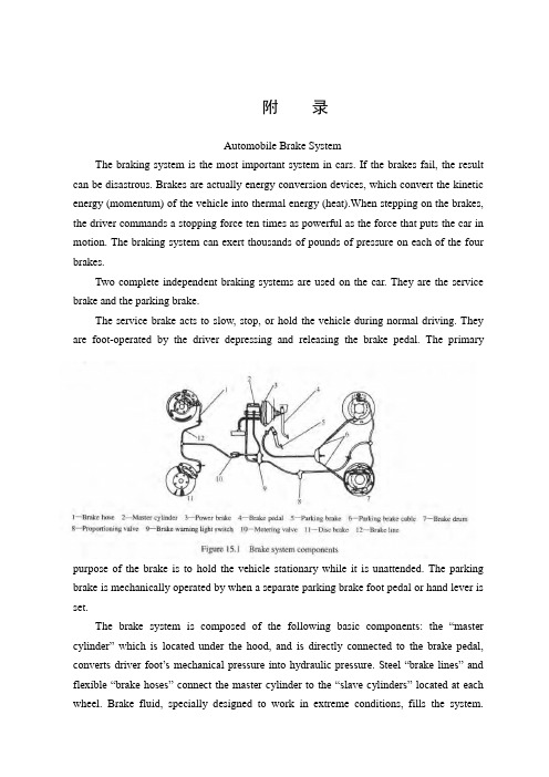
附录Automobile Brake SystemThe braking system is the most important system in cars. If the brakes fail, the result can be disastrous. Brakes are actually energy conversion devices, which convert the kinetic energy (momentum) of the vehicle into thermal energy (heat).When stepping on the brakes, the driver commands a stopping force ten times as powerful as the force that puts the car in motion. The braking system can exert thousands of pounds of pressure on each of the four brakes.Two complete independent braking systems are used on the car. They are the service brake and the parking brake.The service brake acts to slow, stop, or hold the vehicle during normal driving. They are foot-operated by the driver depressing and releasing the brake pedal. The primarypurpose of the brake is to hold the vehicle stationary while it is unattended. The parking brake is mechanically operated by when a separate parking brake foot pedal or hand lever is set.The brake system is composed of the following basic component s: the “master cylinder” which is located under the hood, and is directly connected to the brake pedal, converts driver foot’s mechanical pressure into hydraulic pressure. Steel “brake lines” and flexible “brake hoses” connect the master cylinder to the “slave cylinders” located at each wheel. Brake fluid, specially designed to work in extreme conditions, fills the system.“Shoes” and “pads” are pushed by the slave cylinders to contact the “drums” and “rotors” thus causing drag, which (hopefully) slows the car.The typical brake system consists of disk brakes in front and either disk or drum brakes in the rear connected by a system of tubes and hoses that link the brake at each wheel to the master cylinder (Figure).Basically, all car brakes are friction brakes. When the driver applies the brake, the control device forces brake shoes, or pads, against the rotating brake drum or disks at wheel. Friction between the shoes or pads and the drums or disks then slows or stops the wheel so that the car is braked.In most modern brake systems (see Figure 15.1), there is a fluid-filled cylinder, called master cylinder, which contains two separate sections, there is a piston in each section and both pistons are connected to a brake pedal in the driver’s compartment. Wh en the brake is pushed down, brake fluid is sent from the master cylinder to the wheels. At the wheels, the fluid pushes shoes, or pads, against revolving drums or disks. The friction between the stationary shoes, or pads, and the revolving drums or disks slows and stops them. This slows or stops the revolving wheels, which, in turn, slow or stop the car.The brake fluid reservoir is on top of the master cylinder. Most cars today have a transparent r reservoir so that you can see the level without opening the cover. The brake fluid level will drop slightly as the brake pads wear. This is a normal condition and no cause for concern. If the level drops noticeably over a short period of time or goes down to about two thirds full, have your brakes checked as soon as possible. Keep the reservoir covered except for the amount of time you need to fill it and never leave a cam of brake fluid uncovered. Brake fluid must maintain a very high boiling point. Exposure to air will cause the fluid to absorb moisture which will lower that boiling point.The brake fluid travels from the master cylinder to the wheels through a series of steel tubes and reinforced rubber hoses. Rubber hoses are only used in places that require flexibility, such as at the front wheels, which move up and down as well as steer. The rest of the system uses non-corrosive seamless steel tubing with special fittings at all attachment points. If a steel line requires a repair, the best procedure is to replace the compete line. If this is not practical, a line can be repaired using special splice fittings that are made for brake system repair. You must never use copper tubing to repair a brake system. They are dangerous and illegal.Drum brakes, it consists of the brake drum, an expander, pull back springs, a stationary back plate, two shoes with friction linings, and anchor pins. The stationary back plate is secured to the flange of the axle housing or to the steering knuckle. The brake drum is mounted on the wheel hub. There is a clearance between the inner surface of the drum and the shoe lining. To apply brakes, the driver pushes pedal, the expander expands the shoes and presses them to the drum. Friction between the brake drum and the friction linings brakes the wheels and the vehicle stops. To release brakes, the driver release the pedal, the pull back spring retracts the shoes thus permitting free rotation of the wheels.Disk brakes, it has a metal disk instead of a drum. A flat shoe, or disk-brake pad, is located on each side of the disk. The shoes squeeze the rotating disk to stop the car. Fluid from the master cylinder forces the pistons to move in, toward the disk. This action pushes the friction pads tightly against the disk. The friction between the shoes and disk slows and stops it. This provides the braking action. Pistons are made of either plastic or metal. There are three general types of disk brakes. They are the floating-caliper type, the fixed-caliper type, and the sliding-caliper type. Floating-caliper and sliding-caliper disk brakes use a single piston. Fixed-caliper disk brakes have either two or four pistons.The brake system assemblies are actuated by mechanical, hydraulic or pneumatic devices. The mechanical leverage is used in the parking brakes fitted in all automobile. When the brake pedal is depressed, the rod pushes the piston of brake master cylinder which presses the fluid. The fluid flows through the pipelines to the power brake unit and then to the wheel cylinder. The fluid pressure expands the cylinder pistons thus pressing the shoes to the drum or disk. If the pedal is released, the piston returns to the initial position, the pull back springs retract the shoes, the fluid is forced back to the master cylinder and braking ceases.The primary purpose of the parking brake is to hold the vehicle stationary while it is unattended. The parking brake is mechanically operated by the driver when a separate parking braking hand lever is set. The hand brake is normally used when the car has already stopped. A lever is pulled and the rear brakes are approached and locked in the “on” position. The car may now be left without fear of its rolling away. When the driver wants to move the car again, he must press a button before the lever can be released. The hand brake must also be able to stop the car in the event of the foot brake failing. For this reason, it is separate from the foot brake uses cable or rods instead of the hydraulic system.Anti-lock Brake SystemAnti-lock brake systems make braking safer and more convenient, Anti-lock brake systems modulate brake system hydraulic pressure to prevent the brakes from locking and the tires from skidding on slippery pavement or during a panic stop.Anti-lock brake systems have been used on aircraft for years, and some domestic car were offered with an early form of anti-lock braking in late 1990’s. Recently, several automakers have introduced more sophisticated anti-lock system. Investigations in Europe, where anti-lock braking systems have been available for a decade, have led one manufacture to state that the number of traffic accidents could be reduced by seven and a half percent if all cars had anti-lock brakes. So some sources predict that all cars will offer anti-lock brakes to improve the safety of the car.Anti-lock systems modulate brake application force several times per second to hold the tires at a controlled amount of slip; all systems accomplish this in basically the same way. One or more speed sensors generate alternating current signal whose frequency increases with the wheel rotational speed. An electronic control unit continuously monitors these signals and if the frequency of a signal drops too rapidly indicating that a wheel is about to lock, the control unit instructs a modulating device to reduce hydraulic pressure to the brake at the affected wheel. When sensor signals indicate the wheel is again rotating normally, the control unit allows increased hydraulic pressure to the brake. This release-apply cycle occurs several time per second to “pump” the brakes like a driver might but at a much faster rate.In addition to their basic operation, anti-lock systems have two other things in common. First, they do not operate until the brakes are applied with enough force to lock or nearly lock a wheel. At all other times, the system stands ready to function but does not interfere with normal braking. Second, if the anti-lock system fail in any way, the brakes continue to operate without anti-lock capability. A warning light on the instrument panel alerts the driver when a problem exists in the anti-lock system.The current Bosch component Anti-lock Braking System (ABSⅡ), is a second generation design wildly used by European automakers such as BWM, Mercedes-Benz and Porsche. ABSⅡsystem consists of : four wheel speed sensor, electronic control unit and modulator assembly.A speed sensor is fitted at each wheel sends signals about wheel rotation to control unit.Each speed sensor consists of a sensor unit and a gear wheel. The front sensor mounts to the steering knuckle and its gear wheel is pressed onto the stub axle that rotates with the wheel. The rear sensor mounts the rear suspension member and its gear wheel is pressed onto the axle. The sensor itself is a winding with a magnetic core. The core creates a magnetic field around the winding, and as the teeth of the gear wheel move through this field, an alternating current is induced in the winding. The control unit monitors the rate o change in this frequency to determine impending brake lockup.The control unit’s function can be divided into three parts: signal processing, logic and safety circuitry. The signal processing section is the converter that receives the alternating current signals form the speed sensors and converts them into digital form for the logic section. The logic section then analyzes the digitized signals to calculate any brake pressure changes needed. If impending lockup is sensed, the logic section sends commands to the modulator assembly.Modulator assemblyThe hydraulic modulator assembly regulates pressure to the wheel brakes when it receives commands from the control utuit. The modulator assembly can maintain or reduce pressure over the level it receives from the master cylinder, it also can never apply the brakes by itself. The modulator assembly consists of three high-speed electric solenoid valves, two fluid reservoirs and a turn delivery pump equipped with inlet and outlet check valves. The modulator electrical connector and controlling relays are concealed under a plastic cover of the assembly.Each front wheel is served by electric solenoid valve modulated independently by the control unit. The rear brakes are served by a single solenoid valve and modulated together using the select-low principle. During anti-braking system operation, the control unit cycles the solenoid valves to either hold or release pressure the brake lines. When pressure is released from the brake lines during anti-braking operation, it is routed to a fluid reservoir. There is one reservoir for the front brake circuit. The reservoirs are low-pressure accumulators that store fluid under slight spring pressure until the return delivery pump can return the fluid through the brake lines to the master cylinder.汽车制动系统制动系统是汽车中最重要的系统。
外文翻译---汽车制动系统

附录1外文翻译Automobile Brake SystemThe braking system is the most important system in cars. If the brakes fail, the result can be disastrous. Brakes are actually energy conversion devices, which convert the kinetic energy (momentum) of the vehicle into thermal energy (heat).When stepping on the brakes, the driver commands a stopping force ten times as powerful as the force that puts the car in motion. The braking system can exert thousands of pounds of pressure on each of the four brakes.Two complete independent braking systems are used on the car. They are the service brake and the parking brake.The service brake acts to slow, stop, or hold the vehicle during normal driving. They are foot-operated by the driver depressing and releasing the brake pedal. The primary purpose of the brake is to hold the vehicle stationary while it is unattended. The parking brake is mechanically operated by when a separate parking brake footpedal or hand lever is set.The brake system is composed of the following basic components: the “master cylinder” which is located under the hood, and is directly connected to the brake pedal, converts driver foot’s mechanical pressure into hydraulic pressure. Steel “brake lines” and flexible “brake hoses” connect the master cylinder to the “slave cylinders” located at each wheel. Brake fluid, specially designed to work in extreme conditions, fills thesystem. “Shoes” and “pads” are pushed by the slave cylinders to contact the “drums” and “rotors” thus causing drag, which (hopefully) s lows the car.The typical brake system consists of disk brakes in front and either disk or drum brakes in the rear connected by a system of tubes and hoses that link the brake at each wheel to the master cylinder (Figure).Basically, all car brakes are friction brakes. When the driver applies the brake, the control device forces brake shoes, or pads, against the rotating brake drum or disks at wheel. Friction between the shoes or pads and the drums or disks then slows or stops the wheel so that the car is braked.In most modern brake systems (see Figure 15.1), there is a fluid-filled cylinder, called master cylinder, which contains two separate sections, there is a piston in each section and both pistons are connected to a brake pedal in the driver’s compartment. When the brake is pushed down, brake fluid is sent from the master cylinder to the wheels. At the wheels, the fluid pushes shoes, or pads, against revolving drums or disks. The friction between the stationary shoes, or pads, and the revolving drums or disks slows and stops them. This slows or stops the revolving wheels, which, in turn, slow or stop the car.The brake fluid reservoir is on top of the master cylinder. Most cars today have a transparent r reservoir so that you can see the level without opening the cover. The brake fluid level will drop slightly as the brake pads wear. This is a normal condition and no cause for concern. If the level drops noticeably over a short period of time or goes down to about two thirds full, have your brakes checked as soon as possible. Keep the reservoir covered except for the amount of time you need to fill it and never leave a cam of brake fluid uncovered. Brake fluid must maintain a very high boiling point. Exposure to air will cause the fluid to absorb moisture which will lower that boiling point.The brake fluid travels from the master cylinder to the wheels through a series of steel tubes and reinforced rubber hoses. Rubber hoses are only used in places that require flexibility, such as at the front wheels, which move up and down as well as steer. The rest of the system uses non-corrosive seamless steel tubing with special fittings at all attachment points. If a steel line requires a repair, the best procedure is to replace the compete line. If this is not practical, a line can be repaired using special splice fittings that are made for brake system repair. You must never use copper tubing to repair a brake system. They are dangerous and illegal.Drum brakes, it consists of the brake drum, an expander, pull back springs, a stationary back plate, two shoes with friction linings, and anchor pins. The stationary back plate is secured to the flange of the axle housing or to the steering knuckle. The brake drum is mounted on the wheel hub. There is a clearance between the inner surface of the drum and the shoe lining. To apply brakes, the driver pushes pedal, theexpander expands the shoes and presses them to the drum. Friction between the brake drum and the friction linings brakes the wheels and the vehicle stops. To release brakes, the driver release the pedal, the pull back spring retracts the shoes thus permitting free rotation of the wheels.Disk brakes, it has a metal disk instead of a drum. A flat shoe, or disk-brake pad, is located on each side of the disk. The shoes squeeze the rotating disk to stop the car. Fluid from the master cylinder forces the pistons to move in, toward the disk. This action pushes the friction pads tightly against the disk. The friction between the shoes and disk slows and stops it. This provides the braking action. Pistons are made of either plastic or metal. There are three general types of disk brakes. They are the floating-caliper type, the fixed-caliper type, and the sliding-caliper type. Floating-caliper and sliding-caliper disk brakes use a single piston. Fixed-caliper disk brakes have either two or four pistons.The brake system assemblies are actuated by mechanical, hydraulic or pneumatic devices. The mechanical leverage is used in the parking brakes fitted in all automobile. When the brake pedal is depressed, the rod pushes the piston of brake master cylinder which presses the fluid. The fluid flows through the pipelines to the power brake unit and then to the wheel cylinder. The fluid pressure expands the cylinder pistons thus pressing the shoes to the drum or disk. If the pedal is released, the piston returns to the initial position, the pull back springs retract the shoes, the fluid is forced back to the master cylinder and braking ceases.The primary purpose of the parking brake is to hold the vehicle stationary while it is unattended. The parking brake is mechanically operated by the driver when a separate parking braking hand lever is set. The hand brake is normally used when the car has already stopped. A lever is pulled and the rear brakes are approached and locked in the “on” position. The car may now be left without fear of its rolling away. When the driver wants to move the car again, he must press a button before the lever can be released. The hand brake must also be able to stop the car in the event of the foot brake failing. For this reason, it is separate from the foot brake uses cable or rods instead of the hydraulic system.Anti-lock Brake SystemAnti-lock brake systems make braking safer and more convenient, Anti-lock brake systems modulate brake system hydraulic pressure to prevent the brakes from locking and the tires from skidding on slippery pavement or during a panic stop.Anti-lock brake systems have been used on aircraft for years, and some domestic car were offered with an early form of anti-lock braking in late 1990’s. Recently, several automakers have introduced more sophisticated anti-lock system. Investigations in Europe, where anti-lock braking systems have been available for a decade, have led one manufacture to state that the number of traffic accidents could bereduced by seven and a half percent if all cars had anti-lock brakes. So some sources predict that all cars will offer anti-lock brakes to improve the safety of the car.Anti-lock systems modulate brake application force several times per second to hold the tires at a controlled amount of slip; all systems accomplish this in basically the same way. One or more speed sensors generate alternating current signal whose frequency increases with the wheel rotational speed. An electronic control unit continuously monitors these signals and if the frequency of a signal drops too rapidly indicating that a wheel is about to lock, the control unit instructs a modulating deviceto reduce hydraulic pressure to the brake at the affected wheel. When sensor signals indicate the wheel is again rotating normally, the control unit allows increased hydraulic pressure to the brake. This release-apply cycle occurs several time per second to “pump” the br akes like a driver might but at a much faster rate.In addition to their basic operation, anti-lock systems have two other things in common. First, they do not operate until the brakes are applied with enough force to lock or nearly lock a wheel. At all other times, the system stands ready to function but does not interfere with normal braking. Second, if the anti-lock system fail in any way, the brakes continue to operate without anti-lock capability. A warning light on the instrument panel alerts the driver when a problem exists in the anti-lock system.The current Bosch component Anti-lock Braking System (ABSⅡ), is a second generation design wildly used by European automakers such as BWM, Mercedes-Benz and Porsche. ABSⅡsystem consists of : four wheel speed sensor, electronic control unit and modulator assembly.A speed sensor is fitted at each wheel sends signals about wheel rotation to control unit. Each speed sensor consists of a sensor unit and a gear wheel. The front sensor mounts to the steering knuckle and its gear wheel is pressed onto the stub axle that rotates with the wheel. The rear sensor mounts the rear suspension member and its gear wheel is pressed onto the axle. The sensor itself is a winding with a magnetic core. The core creates a magnetic field around the winding, and as the teeth of the gear wheel move through this field, an alternating current is induced in the winding. The control unit monitors the rate o change in this frequency to determine impending brake lockup.The contr ol unit’s function can be divided into three parts: signal processing, logic and safety circuitry. The signal processing section is the converter that receives the alternating current signals form the speed sensors and converts them into digital form for the logic section. The logic section then analyzes the digitized signals to calculate any brake pressure changes needed. If impending lockup is sensed, the logic section sends commands to the modulator assembly.Modulator assemblyThe hydraulic modulator assembly regulates pressure to the wheel brakes when it receives commands from the control utuit. The modulator assembly can maintain or reduce pressure over the level it receives from the master cylinder, it also can never apply the brakes by itself. The modulator assembly consists of three high-speed electric solenoid valves, two fluid reservoirs and a turn delivery pump equipped with inlet and outlet check valves. The modulator electrical connector and controlling relays are concealed under a plastic cover of the assembly.Each front wheel is served by electric solenoid valve modulated independently by the control unit. The rear brakes are served by a single solenoid valve and modulated together using the select-low principle. During anti-braking system operation, the control unit cycles the solenoid valves to either hold or release pressure the brake lines. When pressure is released from the brake lines during anti-braking operation, it is routed to a fluid reservoir. There is one reservoir for the front brake circuit. The reservoirs are low-pressure accumulators that store fluid under slight spring pressure until the return delivery pump can return the fluid through the brake lines to the master cylinder.译文汽车制动系统制动系统是汽车中最重要的系统。
(机械毕业设计)浅谈汽车制动系统及其发展趋势--英文文献翻译(中文+英文)[管理资料]
![(机械毕业设计)浅谈汽车制动系统及其发展趋势--英文文献翻译(中文+英文)[管理资料]](https://img.taocdn.com/s3/m/866400bac850ad02df8041b0.png)
附录A:浅谈汽车制动系统及其发展趋势制动系统作用是:使行驶中的汽车按照驾驶员的要求进行强制减速甚至停车;使已停驶的汽车在各种道路条件下(包括在坡道上)稳定驻车;使下坡行驶的汽车速度保持稳定。
对汽车起制动作用的只能是作用在汽车上且方向与汽车行驶方向相反的外力,而这些外力的大小都是随机的、不可控制的,因此汽车上必须装设一系列专门装置以实现上述功能。
汽车制动系统是指为了在技术上保证汽车的安全行驶,提高汽车的平均赞叹速度等,而在汽车上安装制动装置专门的制动机构。
一般来说汽车制动系统包括行车制动装置和停车制动装置两套独立的装置。
其中行车制动装置是由驾驶员用脚来操纵的,故又称脚制动装置。
停车制动装置是由驾驶员用手操纵的,故又称手制动装置。
行车制动装置的功用是使正在行驶中的汽车减速或在最短的距离内停车。
而停车制动装置的功用是使已经停在各种路面上的汽车保持不动。
但是,有时在紧急情况下,两种制动装置可同时使用而增加汽车制动的效果。
有些特殊用途的汽车和经常在山区行驶的汽车,长期而又频繁地制动将导致行车制动装置过热,因此在这些汽车上往往增设各种不同型式的辅助制动装置,以便在下坡时稳定车速。
按照制动能源情况,制动系还可分为人力制动系、动力制动系、和伺服制动系等3种。
人力制动系以驾驶员的体力作为制动能源;动力制动系以发动机动力所转化的气压或液压作为制动能源;而伺服制动系则是兼用人力和发动机动力作为制动能源。
此外,按照制动能量的传递方式,制动系又可分为机械式、液压式、气压式和电磁式等到几种。
在种类汽车制动系统中,制动器是汽车制动系中用以产生阻止车辆运动或运动趋势的力的部件。
目前,种类汽车所使用的制动器都是摩擦制动器,也就是阻止汽车运动的制动力矩来源于固定元件和旋转工作表面之间的摩擦。
形式分类鼓式刹车鼓式刹车是一种传统的制动系统,其工作原理可以很形象地用一只咖啡杯来形容.刹车鼓就像咖啡杯,当您将五个手指伸入旋转的咖啡杯时,手指就是刹车片,只要您将五指向外一张,摩擦咖啡杯内壁,咖啡杯就会停止旋转.汽车上的鼓式刹车简单点说是由制动油泵,活塞,刹车片和鼓室组成,刹车时由制动分泵的高压刹车油推动活塞,对两片半月形的制动蹄片施加作用力,使其压紧鼓室内壁,靠摩擦力阻止刹车鼓转动从而达到制动效果。
【机械类文献翻译】汽车制动系统

外文Automobile Brake SystemThe braking system is the most important system in cars.If the brakes fail,the result can be disastrous.Brakes are actually energy conversion devices,which convert the kinetic energy(momentum)of the vehicle into thermal energy(heat).When stepping on the brakes,the driver commands a stopping force ten times as powerful as the force that puts the car in motion.The braking system can exert thousands of pounds of pressure on each of the four brakes.Two complete independent braking systems are used on the car.They are the service brake and the parking brake.The service brake acts to slow,stop,or hold the vehicle during normal driving.They are foot-operated by the driver depressing and releasing the brake pedal.The primary purpose of the brake is to hold the vehicle stationary while it is unattended.The parking brake is mechanically operated by when a separate parking brake foot pedal or hand lever is set.The brake system is composed of the following basic components:the “master cylinder”which is located under the hood,and is directly connected to the brake pedal,converts driver foot’s mechanical pressure into hydraulic pressure.Steel“brake lines”and flexible“brake hoses”connect the master cylinder to the“slave cylinders”located at each wheel.Brake fluid,specially designed to work in extreme conditions,fills the system.“Shoes”and“pads”are pushed by the slave cylinders to contact the“drums”and“rotors”thus causing drag, which(hopefully)slows the car.The typical brake system consists of disk brakes in front and either disk or drum brakes in the rear connected by a system of tubes and hoses that link the brake at each wheel to the master cylinder(Figure).Basically,all car brakes are friction brakes.When the driver applies the brake,the control device forces brake shoes,or pads,against the rotating brake drum or disks at wheel.Friction between the shoes or padsand the drums or disks then slows or stops the wheel so that the car is braked.In most modern brake systems(see Figure15.1),there is afluid-filled cylinder,called master cylinder,which contains two separate sections,there is a piston in each section and both pistons are connected to a brake pedal in the driver’s compartment.When the brake is pushed down,brake fluid is sent from the master cylinder to the wheels. At the wheels,the fluid pushes shoes,or pads,against revolving drums or disks.The friction between the stationary shoes,or pads,and the revolving drums or disks slows and stops them.This slows or stops the revolving wheels,which,in turn,slow or stop the car.The brake fluid reservoir is on top of the master cylinder.Most cars today have a transparent r reservoir so that you can see the level without opening the cover.The brake fluid level will drop slightly as the brake pads wear.This is a normal condition and no cause for concern.If the level drops noticeably over ashort period of time or goes down to about two thirds full,have your brakes checked as soon as possible.Keep the reservoir covered except for the amount of time you need to fill it and never leave a cam of brake fluid uncovered.Brake fluid must maintain a very high boiling point.Exposure to air will cause the fluid to absorb moisture which will lower that boiling point.The brake fluid travels from the master cylinder to the wheels through a series of steel tubes and reinforced rubber hoses.Rubber hoses are only used in places that require flexibility,such as at the front wheels,which move up and down as well as steer.The rest of the system uses non-corrosive seamless steel tubing with special fittings at all attachment points.If a steel line requires a repair,the best procedure is to replace the compete line.If this is not practical,a line can be repaired using special splice fittings that are made for brake system repair.You must never use copper tubing to repair a brake system.They are dangerous and illegal.Drum brakes,it consists of the brake drum,an expander,pull back springs,a stationary back plate,two shoes with friction linings,andanchor pins.The stationary back plate is secured to the flange of the axle housing or to the steering knuckle.The brake drum is mounted on the wheel hub.There is a clearance between the inner surface of the drum and the shoe lining.To apply brakes,the driver pushes pedal,the expander expands the shoes and presses them to the drum.Friction between the brake drum and the friction linings brakes the wheels and the vehicle stops. To release brakes,the driver release the pedal,the pull back spring retracts the shoes thus permitting free rotation of the wheels.Disk brakes,it has a metal disk instead of a drum.A flat shoe,or disk-brake pad,is located on each side of the disk.The shoes squeeze the rotating disk to stop the car.Fluid from the master cylinder forces the pistons to move in,toward the disk.This action pushes the friction pads tightly against the disk.The friction between the shoes and disk slows and stops it.This provides the braking action.Pistons are made of either plastic or metal.There are three general types of disk brakes. They are the floating-caliper type,the fixed-caliper type,and the sliding-caliper type.Floating-caliper and sliding-caliper disk brakes use a single piston.Fixed-caliper disk brakes have either two or four pistons.The brake system assemblies are actuated by mechanical,hydraulic or pneumatic devices.The mechanical leverage is used in the parking brakes fitted in all automobile.When the brake pedal is depressed,the rod pushes the piston of brake master cylinder which presses the fluid.The fluid flows through the pipelines to the power brake unit and then to the wheel cylinder.The fluid pressure expands the cylinder pistons thus pressing the shoes to the drum or disk.If the pedal is released,the piston returns to the initial position,the pull back springs retract the shoes,the fluid is forced back to the master cylinder and braking ceases.The primary purpose of the parking brake is to hold the vehicle stationary while it is unattended.The parking brake is mechanically operated by the driver when a separate parking braking hand lever is set. The hand brake is normally used when the car has already stopped.A lever is pulled and the rear brakes are approached and locked in the“on”position.The car may now be left without fear of its rolling away.When the driver wants to move the car again,he must press a button before thelever can be released.The hand brake must also be able to stop the car in the event of the foot brake failing.For this reason,it is separate from the foot brake uses cable or rods instead of the hydraulic system.Anti-lock Brake System Anti-lock brake systems make braking safer and more convenient,Anti-lock brake systems modulate brake system hydraulic pressure to prevent the brakes from locking and the tires from skidding on slippery pavement or during a panic stop.Anti-lock brake systems have been used on aircraft for years,and some domestic car were offered with an early form of anti-lock braking in late 1990’s.Recently,several automakers have introduced more sophisticated anti-lock system.Investigations in Europe,where anti-lock braking systems have been available for a decade,have led one manufacture to state that the number of traffic accidents could be reduced by seven and a half percent if all cars had anti-lock brakes.So some sources predict that all cars will offer anti-lock brakes to improve the safety of the car.Anti-lock systems modulate brake application force several times per second to hold the tires at a controlled amount of slip;all systems accomplish this in basically the same way.One or more speed sensors generate alternating current signal whose frequency increases with the wheel rotational speed.An electronic control unit continuously monitors these signals and if the frequency of a signal drops too rapidly indicating that a wheel is about to lock,the control unit instructs a modulating device to reduce hydraulic pressure to the brake at the affected wheel. When sensor signals indicate the wheel is again rotating normally,the control unit allows increased hydraulic pressure to the brake.This release-apply cycle occurs several time per second to“pump”the brakes like a driver might but at a much faster rate.In addition to their basic operation,anti-lock systems have two other things in common.First,they do not operate until the brakes are applied with enough force to lock or nearly lock a wheel.At all other times,the system stands ready to function but does not interfere with normal braking. Second,if the anti-lock systemThe current Bosch component Anti-lock Braking System(ABSⅡ),is a second generation design wildly used by European automakers such as BWM,Mercedes-Benz and Porsche.ABSⅡsystem consists of:four wheel speed sensor,electronic control unit and modulator assembly.A speed sensor is fitted at each wheel sends signals about wheel rotation to control unit.Each speed sensor consists of a sensor unit and a gear wheel.The front sensor mounts to the steering knuckle and its gear wheel is pressed onto the stub axle that rotates with the wheel.The rear sensor mounts the rear suspension member and its gear wheel is pressed onto the axle.The sensor itself is a winding with a magnetic core.The core creates a magnetic field around the winding,and as the teeth of the gear wheel move through this field,an alternating current is induced in the winding.The control unit monitors the rate o change in this frequency to determine impending brake lockup.The control unit’s function can be divided into three parts:signal processing,logic and safety circuitry.The signal processing section is the converter that receives the alternating current signals form the speed sensors and converts them into digital form for the logic section.The logic section then analyzes the digitized signals to calculate any brake pressure changes needed.If impending lockup is sensed,the logic section sends commands to the modulator assembly.Modulator assembly The hydraulic modulator assembly regulates pressure to the wheel brakes when it receives commands from the control utuit.The modulator assembly can maintain or reduce pressure over the level it receives from the master cylinder,it also can never apply the brakes by itself.The modulator assembly consists of three high-speed electric solenoid valves,two fluid reservoirs and a turn delivery pump equipped with inlet and outlet check valves.The modulator electrical connector and controlling relays are concealed under a plastic cover of the assembly.Each front wheel is served by electric solenoid valve modulated independently by the control unit.The rear brakes are served by a single solenoid valve and modulated together using the select-low principle. During anti-braking system operation,the control unit cycles the solenoid valves to either hold or release pressure the brake lines.When pressure is released from the brake lines during anti-braking operation, it is routed to a fluid reservoir.There is one reservoir for the frontbrake circuit.The reservoirs are low-pressure accumulators that store fluid under slight spring pressure until the return delivery pump can return the fluid through the brake lines to the master cylinder.译文汽车制动系统汽车中最重要的系统。
毕业设计论文外文文献翻译汽车专业汽修点火系统中英文对照
Ignition SystemThe purpose of the ignition system is to create a spark that will ignite the fuel-air mixture in the cylinder of an engine. It must do this at exactly the right instant and do it at the rate of up to several thousand times per minute for each cylinder in the engine. If the timing of that spark is off by a small fraction of a second, the engine will run poorly or not run at all.The ignition system sends an extremely high voltage to the spark plug in each cylinder when the piston is at the top of its compression stroke. The tip of each spark plug contains a gap that the voltage must jump across in order to reach ground. That is where the spark occurs.The voltage that is available to the spark plug is somewhere between 20,000 volts and 50,000 volts or better. The job of the ignition system is to produce that high voltage from a 12 volt source and get it to each cylinder in a specific order, at exactly the right time.The ignition system has two tasks to perform. First, it must create a voltage high enough (20,000+) to across the gap of a spark plug, thus creating a spark strong enough to ignite the air/fuel mixture for combustion. Second, it must control the timing of that the spark so it occurs at the exact right time and send it to the correct cylinder.The ignition system is divided into two sections, the primary circuit and the secondary circuit. The low voltage primary circuit operates at battery voltage (12 to 14.5 volts) and is responsible for generating the signal to fire the spark plug at the exact right time and sending that signal to the ignition coil. The ignition coil is the component that converts the 12 volt signal into the high 20,000+ volt charge. Once the voltage is stepped up, it goes to the secondary circuit which then directs the charge to the correct spark plug at the right time.The BasicsBefore we begin this discussion, let’’s talk a bit about electricity in general. I know that this is Before we begin this discussion, letbasic stuff, but there was a time that you didn’’t know about this and there are people who need basic stuff, but there was a time that you didnto know the basics so that they could make sense of what follows.All automobiles work on DC (Direct Current). This means that current move in one direction, form the positive battery terminal to the negative battery terminal. In the case of the automobile, the negative battery terminal is connected by a heavy cable directly to the body and the engine block of the vehicle. The body and any metal component in contact with it is called the ground. This means that a circuit that needs to send current back to the negative side of the battery can be connected to any part of the vehicle’’s metal body or the metal engine block.be connected to any part of the vehicleA good example to see how this works is the headlight circuit. The headlight circuit consists of a wire that goes from the positive battery terminal to the headlight switch. Another wire goes from the headlight switch to one of two terminals on the headlight bulb. Finally, a third wire goes from a second terminal on the bulb to the metal body of car. When you switch the headlight on, you are connecting the wire from the battery with the wire to the headlamps allowing battery current to go directly to the headlamp bulbs. Electricity passes through the filaments inside the bulb, then out the other wire to the metal body. From there, the current goes back to the negative terminal of the battery completing the circuit. Once the current is flowing through this circuit, the filament inside the headlamp gets hot and glows brightly. Let there be light.Now, back to the ignition system, the basic principle of the electrical spark ignition system has not changed for over 75 years. What has changed is the method by which the spark is created and how it is distribute.Currently, there are three distinct types of ignition system. The mechanical ignition systemwas used prior to 1975. It was mechanical and electrical and used no electronics. By understanding these early system, it will be easier to understand the new electronic andcomputer controlled ignition system, so don’’t skip over it. The electronic ignition system started computer controlled ignition system, so donfinding its way to production vehicles during the early 70s and became popular when better control and improved reliability became important with the advent of emission controls. Finally, the distributor less ignition system became available in the mid 80s. This system was always computer controlled and contained no moving parts, so reliability was greatly improved. Most of these systems required no maintenance except replacing the spark plugs at intervals from 60,000 to over 100,000 miles.Let’’s take a detailed look at each system and see how they work.LetThe Mechanical Ignition SystemThe distributor is the nerve center of the mechanical ignition system and has two tasks to perform. First, it is responsible for triggering coil to generate a spark at the precise instant that it is required (which varies depending how fast the engine is turning and how much load it is under). Second, the distributor is responsible for directing that spark to the proper cylinder (which is why it is called a distributor).The circuit that powers the ignition system is simple and straight forward. When you insert the key in the ignition switch and turn the key to the Run position, you are sending current from the battery through a wire directly to the positive (+) side of the ignition coil. Inside the coil is a series of copper windings that loop around the coil over a hundred times before exiting out the negative (-) side of the coil. From there, a wire takes this current over to the distributor and is connected to a special on/off switch, called the points. When the points are closed, this current goes directly to ground. When current flows from the ignition switch, through the windings in the coil, then to ground, it builds a strong magnetic field inside the coil.The points are made up of a fixed contact point that is fastened to a plate inside the distributor, and a movable contact point mounted on the end of a spring loaded arm. The movable point rides on a 4, 6, or 8 lobe cam (depending on the number of cylinder in the engine) that is mounted on a rotating shaft inside the distributor. This distributor cam rotates in time with the engine, making one complete revolution for every two revolutions of the engine. As it rotates, the cam pushes the points open and closed. Every time the points open, the flow of current is interrupted through the coil, thereby collapsing the magnetic field and releasing a high voltage surge through the secondary coil windings. This voltage surge goes out the top of the coil and through the high-tension coil wire.Now, we have the voltage necessary to fire the spark plug, but we still have to get it to the correct cylinder. The coil wire goes from the coil directly to the distributor cap. Under the cap is a rotor that is mounted on top of the rotating shaft. The rotor has a metal strip on the top that is in constant contact with the center terminal of the distributor cap. It receives the high voltage surge from the coil wire and sends it to the other end of the rotor which rotates past each spark plug terminal inside the cap. As the rotor turns on the shaft, it sends the voltage to the correct spark plug wire, which in turn sends it to the spark plug. The voltage enters the spark plug at the terminal at the top and travels down the core until it reaches the tip. It then jumps across the tip of the spark plug, creating a spark suitable to ignite the fuel-air mixture inside that cylinder. The description I just provided is the simplified version, but should be helpful to visualize the process, but we left out a few things that make up this type of ignition system. For instance, we didn’’t talk about the condenser that is connected to the point, nor did we talk about the system didnto advance the timing. Let’’s take a look at each section and explore it in more detail.to advance the timing. LetThe Ignition SwitchThere are two separate circuits that go from the ignition switch to the coil. One circuit runs through a resistor in order to step down the voltage about 15% in order to protect the points from premature wear. The other circuit sends full battery voltage to the coil. The only time this circuit is used is during cranking. Since the starter draws a considerable amount of current to crank the engine, additional voltage is needed to power the coil. So when the key is turned to the spring-loaded start position, full battery voltage is used. As soon as the engine is running, the driver releases the key to the run position which directs current through the primary resistor to the coil.On some vehicles, the primary resistor is mounted on the firewall and is easy to replace if it fails. On other vehicles, most notably vehicles manufactured by GM, the primary resister is a special resister wire and is bundled in the wiring harness with other wires, making it more difficult to replace, but also more durable.The DistributorWhen you remove the distributor cap from the top of the distributor, you will see the points and condenser. The condenser is a simple capacitor that can store a small amount of current. When the points begin to open the current, flowing through the points looks for an alternative path to ground. If the condenser were not there, it would try to jump across the gap of the point as they begin to open. If this were allowed to happen, the points would quickly burn up and you would hear heavy static on the car radio. To prevent this, the condenser acts like a path to ground. It really is not, but by the time the condenser is saturated, the points are too far apart for the small amount of voltage to jump across the wide point gap. Since the arcing across the opening points is eliminated, the points last longer and there is no static on the radio from point arcing.The points require periodic adjustments in order to keep the engine running at peek efficiency. This is because there is a rubbing block on the points that is in contact with the cam and this rubbing block wears out over time changing he point gap. There are two ways that the points can be measured to see if they need an adjustment. One way is by measuring the gap between the open points when the rubbing block is on the high point of the cam. The other way is by measuring the dwell electrically. The dwell is the amount, in degrees of cam rotation that the points stay closed.On some vehicles, points are adjusted with the engine off and the distributor cap removed. A mechanic will loosen the fixed point and move it slightly, then retighten it in the correct position using a feeler gauge to measure the gap. On other vehicles, most notably GM cars, there is a window in the distributor where a mechanic can insert a tool and adjust the points using a dwell meter while the engine is running. Measuring dwell is much more accurate than setting the points with a feeler gauge.Points have a life expectancy of about 10,000 miles at which time have to be replaced. This is done during a routine major tune up, points, condenser, and the spark plugs are replaced, the timing is set and the carburetor is adjusted. In some cases, to keep the engine running efficiently, a minor tune up would be performed at 5,000 mile increments to adjust the point and reset the timing.Ignition CoilThe ignition coil is nothing more that an electrical transformer. It contains both primary and secondary winding circuit. The coil primary winding contains 100 to 150 turns of heavy copper wire. This wire must be insulated so that the voltage does not jump from loop to loop, shortingit out. If this happened, it could not create the primary magnetic field that is required. The primary circuit wire goes into the coil through the positive terminal, loops around the primary windings, then exits through the negative terminal.The coil secondary winding circuit contains 15,000 to 30,000 turns of fine copper wire, which also must be insulated from each other. The secondary windings sit inside the loops of the primary windings. To further increase the coils magnetic field the windings are wrapped around a soft iron core. To withstand the heat of the current flow, the coil is filled with oil which helps keep it cool.The ignition coil is the heart of the ignition system. As current flows through the coil a strong magnetic field is build up. When the current is shut off, the collapse of this magnetic field to the secondary windings induces a high voltage which is released through the large center terminal. This voltage is then directed to the spark plugs through the distributor.Ignition Timing The timing is set by loosening a hold-down screw and rotating the body of the distributor. Since the spark is triggered at the exact instant that the points begin to open, rotating the distributor body (which the point are mounted on) will change the relationship between the position and the position of the distributor cam, which is on the shaft that is geared to the engine rotation.While setting the initial or base timing is important, for an engine to run properly, the timing needs to change depending on the speed of the engine and the load that it is under. If we can move the plate that the points are mounted on, or we could change the position of the distributor cam in relation to the gear that drives it, we can alter the timing dynamically to suit the needs of the engine.Ignition Wires These cables are designed to handle 20,000 to more than 50,000 volts, enough voltage to toss you across the room if you were to be exposed to it. The job of the spark plug wires is to get that enormous power to the spark plug without leaking out. Spark plug wires have to endure the heat of a running engine as well as the extreme changes in the weather. In order to do their job, spark plug wires are fairly thick, with most of that thickness devoted to insulation with a very thin conductor running down the center. Eventually, the insulation will succumb to the elements and the heat of the engine and begins to harden, crack, dry out, or otherwise break down. When that happens, they will not be able to deliver the necessary voltage to the spark plug and a misfire will occur. That is what is meant by “Not running on all cylinders cylinders””. To correct this problem, the spark plug wires would have to be replaced.Spark plug wires are routed around the engine very carefully. Plastic clips are often used to keep the wires separated so that they do not touch together. This is not always necessary, especially when the wires are new, but as they age, they can begin to leak and crossfire on damp days causing hard starting or a rough running engine.Spark plug wires go from the distributor cap to the spark plugs in a very specific order. This is called the is called the ““firing order firing order”” and is part of the engine design. Each spark plug must only fire at the end of the compression stroke. Each cylinder has a compression stroke at a different time, so it is important for the individual spark plug wire to be routed to the correct cylinder.For instance, a popular V8 engine firing order is 1, 8, 4, 3, 6, 5, 7, 2. The cylinders are numbered from the front to the rear with cylinder #1 on the front-left of the engine. So the cylinders on the left side of the engine are numbered 1, 3, 5, 7while the right side are numbered 2, 4, 6, 8. On some engine, the right bank is 1, 2, 3, 4 while the left bank is 5, 6, 7, 8. A repairmanual will tell you the correct firing order and cylinder layout for a particular engine.The next thing we need to know is what direction the distributor is rotating in, clockwise or counter-clockwise, and which terminal on the distributor caps that #1 cylinder is located. Once we have this information, we can begin routing the spark plug wires.If the wires are installed incorrectly, the engine may backfire, or at the very least, not run on all cylinders. It is very important that the wires are installed correctly.Spark PlugsThe ignition system system’’s sole reason for being is to service the spark plug. It must provide sufficient voltage to jump the gap at the tip of the spark plug and do it at the exact right time, reliably on the order of thousands of times per minute for each spark plug in the engine.The modern spark plug is designed to last many thousands of miles before it requires replacement. These electrical wonders come in many configurations and heat ranges to work properly in a given engine. The heat range of a spark plug dictates whether it will be hot enough to burn off any residue that collects on the tip, but not so hot that it will cause pre-ignition in the engine. Pre-ignition is caused when a spark plug is so hot, that it begins to glow and ignite the fuel-air mixture prematurely, before the spark. Most spark plugs contain a resistor to suppress radio interference. The gap on a spark plug is also important and must be set before the spark plug is installed in the engine. If the gap is too wide, there may not be enough voltage to jump the gap, causing a misfire. If the gap is too small, the spark may be inadequate to ignite a lean fuel-air mixture also causing a misfire.The Electronic Ignition SystemThis section will describe the main differences between the early point & condenser systems and the newer electronic systems. If you are not familiar with the way an ignition system works in general, I strongly recommend that you first read the previous section The Mechanical Ignition System.In the electronic ignition system, the points and condenser were replaced by electronics. On these systems, there were several methods used to replace the points and condenser in order to trigger the coil to fire. One method used a metal wheel with teeth, usually one for each cylinder. This is called an armature. A magnetic pickup coil senses when a tooth passes and sends a signal to the control module to fire the coil.Other systems used an electric eye with a shutter wheel to send a signal to the electronics that it was time to trigger the coil to fire. These systems still need to have the initial timing adjusted by rotating the distributor housing.The advantage of this system, aside from the fact that it is maintenance free, is that the control module can handle much higher primary voltage than the mechanical point. V control module can handle much higher primary voltage than the mechanical point. Voltage can oltage can even be stepped up before sending it to the coil, so the coil can create a much hotter spark, on the order of 50,000 volts that is common with the mechanical systems. These systems only have a single wire from the ignition switch to the coil since a primary resistor is not longer needed. On some vehicles, this control module was mounted inside the distributor where the points used to be mounted. On other designs, the control module was mounted outside the distributor with external wiring to connect it to the pickup coil. On many General Motors engines, the control module was inside the distributor and the coil was mounted on top of the distributor for a one piece unitized ignition system. GM called it high energy ignition or HEI for short.The higher voltages that these systems provided allow the use of a much wider gap on the spark plugs for a longer, fatter spark. This larger sparks also allowed a leaner mixture for betterfuel economy and still insure a smooth running engine.The early electronic systems had limited or no computing power, so timing still a centrifugal and vacuum advance built into the distributor.On some of the later systems, the inside of the distributor is empty and all triggering is performed by a sensor that watches a notched wheel connected to either the crankshaft or the camshaft. These devices are called crankshaft position sensor or camshaft position sensor. In these systems, the job of the distributor is solely to distribute the spark to the correct cylinder through the distributor cap and rotor. The computer handles the timing and any timing advance necessary for the smooth running of the engine.The Distributor Ignition SystemNewer automobiles have evolved from a mechanical system (distributor) to a completely solid state electronic system with no moving parts. These systems are completely controlled by the on-board computer. In place of the distributor, there are multiple coils that each serves one or two spark plugs. A typical 6 cylinder engine has 3 coils that are mounted together in a coil pack””. A spark plug wire comes out of each side of the individual coil and goes to the “packappropriate spark plug. The coil fires both spark plugs at the same time. One spark plug fires on the compression stroke igniting the fuel-air mixture to produce power while the other spark plug fires on the exhaust stroke and does nothing. On some vehicles, there is an individual coil for each cylinder mounted directly on top of the spark plug. This design completely eliminates the high tension spark plug wires for even better reliability. Most of these systems use spark plugs that are designed to last over 100,000 miles, which cuts down on maintenance costs.参考文献:[1] 王欲进,张红伟汽车专业英语[M]. 北京:北京大学出版社,中国林业出版社,2007.8,55—67点火系统点火系统的作用是产生点燃发动机气缸里可燃混合物的火花。
汽车制动系统外文文献翻译汽车车辆工程类中英文翻译、外文翻译

外文Automobile Brake SystemThe braking system is the most important system in cars. If the brakes fail, the result can be disastrous. Brakes are actually energy conversion devices, which convert the kinetic energy (momentum) of the vehicle into thermal energy (heat).When stepping on the brakes, the driver commands a stopping force ten times as powerful as the force that puts the car in motion. The braking system can exert thousands of pounds of pressure on each of the four brakes.Two complete independent braking systems are used on the car. They are the service brake and the parking brake.The service brake acts to slow, stop, or hold the vehicle during normal driving. They are foot-operated by the driver depressing and releasing the brake pedal. The primary purpose of the brake is to hold the vehicle stationary while it is unattended. The parking brake is mechanically operated by when a separate parking brake foot pedal or hand lever is set.The brake system is composed of the following basic components: the “master cylinder” which is located under the hood, and is directly connected to the brake pedal, converts driver foot’s mechanical pressure into hydraulic pressure. Steel “brake lines” and flexible “brake hoses” connect the master cylinder to the “slave cylinders” located at each wheel. Brake fluid, specially designed to work in extreme conditions, fills the system. “Shoes” and “pads” are pushed by the slave cylinders to contact the “drums” and “rotors” thus causing drag, which (hopefully) slows the car.The typical brake system consists of disk brakes in front and either disk or drum brakes in the rear connected by a system of tubes and hoses that link the brake at each wheel to the master cylinder (Figure).Basically, all car brakes are friction brakes. When the driver applies the brake, the control device forces brake shoes, or pads, against the rotating brake drum or disks at wheel. Friction between the shoes or padsand the drums or disks then slows or stops the wheel so that the car is braked.In most modern brake systems (see Figure 15.1), there is afluid-filled cylinder, called master cylinder, which contains two separate sections, there is a piston in each section and both pistons are connected to a brake pedal in the driver’s compartment. When t he brake is pushed down, brake fluid is sent from the master cylinder to the wheels. At the wheels, the fluid pushes shoes, or pads, against revolving drums or disks. The friction between the stationary shoes, or pads, and the revolving drums or disks slows and stops them. This slows or stops the revolving wheels, which, in turn, slow or stop the car.The brake fluid reservoir is on top of the master cylinder. Most cars today have a transparent r reservoir so that you can see the level without opening the cover. The brake fluid level will drop slightly as the brake pads wear. This is a normal condition and no cause for concern. If the level drops noticeably over ashort period of time or goes down to about two thirds full, have your brakes checked as soon as possible. Keep the reservoir covered except for the amount of time you need to fill it and never leave a cam of brake fluid uncovered. Brake fluid must maintain a very high boiling point. Exposure to air will cause the fluid to absorb moisture which will lower that boiling point.The brake fluid travels from the master cylinder to the wheels through a series of steel tubes and reinforced rubber hoses. Rubber hoses are only used in places that require flexibility, such as at the front wheels, which move up and down as well as steer. The rest of the system uses non-corrosive seamless steel tubing with special fittings at all attachment points. If a steel line requires a repair, the best procedure is to replace the compete line. If this is not practical, a line can be repaired using special splice fittings that are made for brake system repair. You must never use copper tubing to repair a brake system. They are dangerous and illegal.Drum brakes, it consists of the brake drum, an expander, pull back springs, a stationary back plate, two shoes with friction linings, andanchor pins. The stationary back plate is secured to the flange of the axle housing or to the steering knuckle. The brake drum is mounted on the wheel hub. There is a clearance between the inner surface of the drum and the shoe lining. To apply brakes, the driver pushes pedal, the expander expands the shoes and presses them to the drum. Friction between the brake drum and the friction linings brakes the wheels and the vehicle stops. To release brakes, the driver release the pedal, the pull back spring retracts the shoes thus permitting free rotation of the wheels.Disk brakes, it has a metal disk instead of a drum. A flat shoe, or disk-brake pad, is located on each side of the disk. The shoes squeeze the rotating disk to stop the car. Fluid from the master cylinder forces the pistons to move in, toward the disk. This action pushes the friction pads tightly against the disk. The friction between the shoes and disk slows and stops it. This provides the braking action. Pistons are made of either plastic or metal. There are three general types of disk brakes. They are the floating-caliper type, the fixed-caliper type, and the sliding-caliper type. Floating-caliper and sliding-caliper disk brakes use a single piston. Fixed-caliper disk brakes have either two or four pistons.The brake system assemblies are actuated by mechanical, hydraulic or pneumatic devices. The mechanical leverage is used in the parking brakes fitted in all automobile. When the brake pedal is depressed, the rod pushes the piston of brake master cylinder which presses the fluid. The fluid flows through the pipelines to the power brake unit and then to the wheel cylinder. The fluid pressure expands the cylinder pistons thus pressing the shoes to the drum or disk. If the pedal is released, the piston returns to the initial position, the pull back springs retract the shoes, the fluid is forced back to the master cylinder and braking ceases.The primary purpose of the parking brake is to hold the vehicle stationary while it is unattended. The parking brake is mechanically operated by the driver when a separate parking braking hand lever is set. The hand brake is normally used when the car has already stopped. A lever is pulled and the rear br akes are approached and locked in the “on” position. The car may now be left without fear of its rolling away. When the driver wants to move the car again, he must press a button before thelever can be released. The hand brake must also be able to stop the car in the event of the foot brake failing. For this reason, it is separate from the foot brake uses cable or rods instead of the hydraulic system.Anti-lock Brake System Anti-lock brake systems make braking safer and more convenient, Anti-lock brake systems modulate brake system hydraulic pressure to prevent the brakes from locking and the tires from skidding on slippery pavement or during a panic stop.Anti-lock brake systems have been used on aircraft for years, and some domestic car were offered with an early form of anti-lock braking in late 1990’s. Recently, several automakers have introduced more sophisticated anti-lock system. Investigations in Europe, where anti-lock braking systems have been available for a decade, have led one manufacture to state that the number of traffic accidents could be reduced by seven and a half percent if all cars had anti-lock brakes. So some sources predict that all cars will offer anti-lock brakes to improve the safety of the car.Anti-lock systems modulate brake application force several times per second to hold the tires at a controlled amount of slip; all systems accomplish this in basically the same way. One or more speed sensors generate alternating current signal whose frequency increases with the wheel rotational speed. An electronic control unit continuously monitors these signals and if the frequency of a signal drops too rapidly indicating that a wheel is about to lock, the control unit instructs a modulating device to reduce hydraulic pressure to the brake at the affected wheel. When sensor signals indicate the wheel is again rotating normally, the control unit allows increased hydraulic pressure to the brake. This release-apply cycle occurs several time per second to “pump” the brakes like a driver might but at a much faster rate.In addition to their basic operation, anti-lock systems have two other things in common. First, they do not operate until the brakes are applied with enough force to lock or nearly lock a wheel. At all other times, the system stands ready to function but does not interfere with normal braking. Second, if the anti-lock systemThe current Bosch component Anti-lock Braking System (ABSⅡ), is a second generation design wildly used by European automakers such as BWM,Mercedes-Benz and P orsche. ABSⅡ system consists of : four wheel speed sensor, electronic control unit and modulator assembly.A speed sensor is fitted at each wheel sends signals about wheel rotation to control unit. Each speed sensor consists of a sensor unit and a gear wheel. The front sensor mounts to the steering knuckle and its gear wheel is pressed onto the stub axle that rotates with the wheel. The rear sensor mounts the rear suspension member and its gear wheel is pressed onto the axle. The sensor itself is a winding with a magnetic core. The core creates a magnetic field around the winding, and as the teeth of the gear wheel move through this field, an alternating current is induced in the winding. The control unit monitors the rate o change in this frequency to determine impending brake lockup.The control unit’s function can be divided into three parts: signal processing, logic and safety circuitry. The signal processing section is the converter that receives the alternating current signals form the speed sensors and converts them into digital form for the logic section. The logic section then analyzes the digitized signals to calculate any brake pressure changes needed. If impending lockup is sensed, the logic section sends commands to the modulator assembly.Modulator assembly The hydraulic modulator assembly regulates pressure to the wheel brakes when it receives commands from the control utuit. The modulator assembly can maintain or reduce pressure over the level it receives from the master cylinder, it also can never apply the brakes by itself. The modulator assembly consists of three high-speed electric solenoid valves, two fluid reservoirs and a turn delivery pump equipped with inlet and outlet check valves. The modulator electrical connector and controlling relays are concealed under a plastic cover of the assembly.Each front wheel is served by electric solenoid valve modulated independently by the control unit. The rear brakes are served by a single solenoid valve and modulated together using the select-low principle. During anti-braking system operation, the control unit cycles the solenoid valves to either hold or release pressure the brake lines. When pressure is released from the brake lines during anti-braking operation, it is routed to a fluid reservoir. There is one reservoir for the frontbrake circuit. The reservoirs are low-pressure accumulators that store fluid under slight spring pressure until the return delivery pump can return the fluid through the brake lines to the master cylinder.译文汽车制动系统汽车中最重要的系统。
- 1、下载文档前请自行甄别文档内容的完整性,平台不提供额外的编辑、内容补充、找答案等附加服务。
- 2、"仅部分预览"的文档,不可在线预览部分如存在完整性等问题,可反馈申请退款(可完整预览的文档不适用该条件!)。
- 3、如文档侵犯您的权益,请联系客服反馈,我们会尽快为您处理(人工客服工作时间:9:00-18:30)。
毕业设计(论文)外文文献翻译文献、资料中文题目:汽车制动系统文献、资料英文题目:文献、资料来源:文献、资料发表(出版)日期:院(部):专业:汽车检测与维修班级:姓名:学号:指导教师:翻译日期: 2017.02.14Automobile Brake SystemThe braking system is the most important system in cars. If the brakes fail, the result can be disastrous. Brakes are actually energy conversion devices, which convert the kinetic energy (momentum) of the vehicle into thermal energy (heat).When stepping on the brakes, the driver commands a stopping force ten times as powerful as the force that puts the car in motion. The braking system can exert thousands of pounds of pressure on each of the four brakes.Two complete independent braking systems are used on the car. They are the service brake and the parking brake.The service brake acts to slow, stop, or hold the vehicle during normal driving. They are foot-operated by the driver depressing and releasing the brake pedal. The primary purpose of the brake is to hold the vehicle stationary while it is unattended. The parking brake is mechanically operated by when a separate parking brake foot pedal or hand lever is set.The brake system is composed of the following basic components: the “master cylinder” which is located under the hood, and is directly connected to the brake pedal, converts driver foot’s mechanical pressure into hydraulic pressure. Steel “brake lines” and flexible “brake hoses” connect the master cylinder to the “slave cylinders” located at each wheel. Brake fluid, specially designed to work in extreme conditions, fills the system. “Shoes” and “pads” are pushed by the slave cy linders to contact the “drums” and “rotors” thus causing drag, which (hopefully) slows the car.The typical brake system consists of disk brakes in front and either disk or drum brakes in the rear connected by a system of tubes and hoses that link the brake at each wheel to the master cylinder (Figure).Basically, all car brakes are friction brakes. When the driver applies thebrake, the control device forces brake shoes, or pads, against the rotating brake drum or disks at wheel. Friction between the shoes or pads and the drums or disks then slows or stops the wheel so that the car is braked.In most modern brake systems (see Figure 15.1), there is a fluid-filled cylinder, called master cylinder, which contains two separate sections, there is a piston in each section and both pistons are connected to a brake pedal in the driver’s compartment. When the brake is pushed down, brake fluid is sent from the master cylinder to the wheels.At the wheels, the fluid pushes shoes, or pads, against revolving drums or disks. The friction between the stationary shoes, or pads, and the revolving drums or disks slows and stops them. This slows or stops the revolving wheels, which, in turn, slow or stop the car.The brake fluid reservoir is on top of the master cylinder. Most cars today have a transparent r reservoir so that you can see the level without opening the cover. The brake fluid level will drop slightly as the brake pads wear. This is a normal condition and no cause for concern. If the level drops noticeably over ashort period of time or goes down to about two thirds full, have your brakes checked as soon as possible. Keep the reservoir covered except for the amount of time you need to fill it and never leave a cam of brake fluid uncovered. Brake fluid must maintain a very high boiling point. Exposure to air will cause the fluid to absorb moisture which will lower that boiling point.The brake fluid travels from the master cylinder to the wheels through a series of steel tubes and reinforced rubber hoses. Rubber hoses are only used in places that require flexibility, such as at the front wheels, which move up and down as well as steer. The rest of the system uses non-corrosive seamless steel tubing with special fittings at all attachment points. If a steel line requires a repair, the best procedure is to replace the compete line. If this is not practical, a line can be repaired using special splice fittings that are made for brake system repair. You must never use copper tubing to repair a brake system. They are dangerous and illegal.Drum brakes, it consists of the brake drum, an expander, pull back springs, astationary back plate, two shoes with friction linings, and anchor pins. The stationary back plate is secured to the flange of the axle housing or to th e steering knuckle. The brake drum is mounted on the wheel hub. There is a clearance between the inner surface of the drum and the shoe lining. To apply brakes, the driver pushes pedal, the expander expands the shoes and presses them to the drum. Friction between the brake drum and the friction linings brakes the wheels and the vehicle stops. To release brakes, the driver release the pedal, the pull back spring retracts the shoes thus permitting free rotation of the wheels.Disk brakes, it has a metal disk instead of a drum. A flat shoe, or disk-brake pad, is located on each side of the disk. The shoes squeeze the rotatin g disk to stop the car. Fluid from the master cylinder forces the pistons to move in, toward the disk. This action pushes the friction pads tightly against the disk. The friction between the shoes and disk slows and stops it. This provides the braking action. Pistons are made of either plastic or metal. There are three general types of disk brakes. They are the floating-caliper type, the fixed-caliper type, and the sliding-caliper type. Floating-caliper and sliding-caliper disk brakes use a single piston. Fixed-caliper disk brakes have either two or four pistons.The brake system assemblies are actuated by mechanical, hydraulic or pneumatic devices. The mechanical leverage is used in the parking brakes fitted in all automobile. When the brake pedal is depressed, the rod pushes the piston of brake master cylinder which presses the fluid. The fluid flows through the pipelines to the power brake unit and then to the wheel cylinder. The fluid pressure expands the cylinder pistons thus pressing the shoes to the drum or disk. If the pedal is released, the piston returns to the initialposition, the pull back springs retract the shoes, the fluid is forced back to the master cylinder and braking ceases.The primary purpose of the parking brake is to hold the vehicle stationary while it is unattended. The parking brake is mechanically operated by the driver when a separate parking braking hand lever is set. The hand brake is normally used when the car has already stopped. A lever is pulled and the rear brakes are approached and locked in the “on” position. The car may now be left without fearof its rolling away. When the driver wants to move the car again, he must press a button before the lever can be released. The hand brake must also be able to stop the car in the event of the foot brake failing. For this reason, it is separate from the foot brake uses cable or rods instead of the hydraulic system.Anti-lock Brake SystemAnti-lock brake systems make braking safer and more convenient, Anti-lock brake systems modulate brake system hydraulic pressure to prevent the brakes from locking and the tires from skidding on slippery pavement or during a panic stop.Anti-lock brake systems have been used on aircraft for years, and some domestic car were offered with an early form of anti-lock braking in late 1990’s. Recently, several automakers have introduced more sophisticated anti-lock system. Investigations in Europe, where anti-lock brakin g systems have been available for a decade, have led one manufacture to state that the number of traffic accidents could be reduced by seven and a half percent if all cars had anti-lock brakes. So some sources predict that all cars will offer anti-lock brakes to improve the safety of the car.Anti-lock systems modulate brake application force several times per second to hold the tires at a controlled amount of slip; all systems accomplish this in basically the same way. One or more speed sensors generate alternating current signal whose frequency increases with the wheel rotational speed. An electronic control unit continuously monitors these signals and if the frequency of a signal drops too rapidly indicating that a wheel is about to lock, the control unit instructs a modulating device to reduce hydraulic pressure to the brake at the affected wheel. When sensor signals indicate the wheel is again rotating normally, the control unit allows increased hydraulic pressure to the brake. This release-apply cycle occurs several time per second to “pump” the brakes like a driver might but at a much faster rate.In addition to their basic operation, anti-lock systems have two other things in common. First, they do not operate until the brakes are applied with enough force to lock or nearly lock a wheel. At all other times, the system stands ready tofunction but does not interfere with normal braking. Second, if the anti-lock system fail in any way, the brakes continue to operate without anti-lock capability. A warning light on the instrument panel alerts the driver when a problem exists in the anti-lock system.The current Bosch component Anti-lock Braking System (ABSⅡ), is a second generation design wildly used by European automakers such as BWM, Mercedes-Benz and Porsche. ABSⅡ system consists of: four wheel speed sensor, electronic control unit and modulator assembly.A speed sensor is fitted at each wheel sends signals about wheel rotation to control unit. Each speed sensor consists of a sensor unit and a gear wheel. The front sensor mounts to the steering knuckle and its gear wheel is pressed onto the stub axle that rotates with the wheel. The rear sensor mounts the rear suspension member and its gear wheel is pressed onto the axle. The sensor itself is a winding with a magnetic core. The core creates a magnetic field around the winding, and as the teeth of the gear wheel move through this field, an alternating current is induced in the winding. The control unit monitors the rate o change in this frequency to determine impending brake lockup.The control unit’s function can be divided into three p arts: signal processing, logic and safety circuitry. The signal processing section is the converter that receives the alternating current signals form the speed sensors and converts them into digital form for the logic section. The logic section then analyzes the digitized signals to calculate any brake pressure changes needed. If impending lockup is sensed, the logic section sends commands to the modulator assembly.Modulator assemblyThe hydraulic modulator assembly regulates pressure to the wheel brakes when it receives commands from the control utuit. The modulator assembly can maintain or reduce pressure over the level it receives from the master cylinder, it also can never apply the brakes by itself. The modulator assembly consists of three high-speed electric solenoid valves, two fluid reservoirs and a turn delivery pump equipped with inlet and outlet check valves. The modulator electrical connector and controlling relays are concealed under a plastic cover of the。