触摸屏控制芯片ADS7843中文资料(附c语言程序)
触摸屏ADS7843驱动程序
触摸屏ADS7843驱动程序设计//===================================================================== // ADS7843 驱动程序(串行)//硬件连接: DCLK ——P0^0;// CS ——P0^1;// DIN ——P0^2;// BUSY ——P0^3// DOUT ——P0^4// PENIRQ——P3^2;// VDD--逻辑电源(+5V)// VSS--GND(0V)//ADS7843.c//writer:谷雨2008年7月23日于EDA实验室//=====================================================================#i nclude //STC单片机头文件#i nclude#define uint unsigned int#define uchar unsigned charsbit DCLK = P0^0; //时钟信号,下降沿有效sbit CS = P0^1; //片选信号,低电平有效sbit DIN = P0^2; //串行数据输入sbit BUSY = P0^3; //忙信号sbit DOUT = P0^4; //串行数据输出sbit PENIRQ = P3^2; //键盘中断请求信号,低电平(负边沿)有效void Tranfer(char Data);uint average(uint a[8]);//===================================================================== ===============//函数名称:void delay(uint us)//函数功能:延时子函数//入口参数:us 延时时间//出口参数:无//===================================================================== ===============void delay(uint us){while(us--);}//===================================================================== ===============//函数名称:void ADS7843_start(void)//函数功能:ADS7843启动//入口参数:无//出口参数:无//===================================================================== ===============void ADS7843_start(void){DCLK=0;CS=1;DIN=1;DCLK=1;CS=0;}//===================================================================== ===============//函数名称:void ADS7843_wr(uchar dat)//函数功能:写ADS7843//入口参数:dat 写入的数据//出口参数:无//===================================================================== ===============void ADS7843_wr(uchar dat){uchar count;DCLK=0;for(count=0;count<8;count++){dat<<=1;DIN=CY;DCLK=0;_nop_();_nop_();_nop_();DCLK=1;_nop_();_nop_();_nop_();}}//===================================================================== ===============//函数名称:uint ADS7843_rd(void)//函数功能:读ADS7843//入口参数:无//出口参数:读回的坐标值//===================================================================== ===============uint ADS7843_rd(void){uchar count=0;uint dat=0;for(count=0;count<12;count++){dat<<=1;DCLK=1; _nop_();_nop_();_nop_(); //下降沿有效DCLK=0; _nop_();_nop_();_nop_();if(DOUT)dat++;}return(dat);}//===================================================================== ===============//函数名称:void intr0_int()//函数功能:外中断0中断服务函数//入口参数:无//出口参数:无//===================================================================== ===============void intr0_int() interrupt 0 using 2{uint X=0,Y=0,a[4],i,avex,avey,x[8],y[8];IE=0; //关中断delay(100); //中断后延时以消除抖动,使得采样数据更准确if(!PENIRQ){for(i=0;i<8;i++) //进行8次数据采集{ADS7843_start();delay(2);ADS7843_wr(0x90);//送控制字10010000 即用差分方式读X坐标delay(2);DCLK=1;_nop_();_nop_();_nop_();_nop_();DCLK=0;_nop_();_nop_();_nop_();_nop_();X=ADS7843_rd(); //读X轴坐标x[i]=X;ADS7843_wr(0xD0); //送控制字11010000 即用差分方式读Y坐标DCLK=1;_nop_();_nop_();_nop_();_nop_();DCLK=0;_nop_();_nop_();_nop_();_nop_();Y=ADS7843_rd(); //读Y轴坐标y[i]=Y;CS=1;}avex=average(x); //X坐标数据处理a[0]=avex/1000; //发上位机观察结果a[1]=(avex-a[0]*1000)/100;a[2]=(avex-a[0]*1000-a[1]*100)/10;a[3]=avex%10;Tranfer(a[0]+48);Tranfer(a[1]+48);Tranfer(a[2]+48);Tranfer(a[3]+48);avey=average(y); //Y坐标数据处理a[0]=avey/1000; //发上位机观察结果a[1]=(avey-a[0]*1000)/100;a[2]=(avey-a[0]*1000-a[1]*100)/10;a[3]=avey%10;Tranfer(a[0]+48);Tranfer(a[1]+48);Tranfer(a[2]+48);Tranfer(a[3]+48);for(i=0;i<10;i++) //延时,在程序中根据具体情况改动delay(10000);}IE=0x81; //开中断}//===================================================================== ===============//函数名称:void init_serial()//函数功能:初始化串口//入口参数:无//出口参数:无//===================================================================== ===============void init_serial(){TMOD=0x22; //定时器T1使用工作方式2TH1=250; //设置初值TL1=250;TR1=1; //开始计时PCON=0x80; //SMOD=1;SCON=0x50; //工作方式1,波特率9600bit/s,允许接收TI=1;}//===================================================================== ===============//函数名称:void Tranfer(char Data)//函数功能:发送数据程序//入口参数:Data 要发送的数据//出口参数:无//===================================================================== ===============void Tranfer(char Data){while(TI==0);SBUF=Data;TI=0;}//===================================================================== ===============//函数名称:int main()//函数功能:主函数//入口参数:无//出口参数:无//===================================================================== ===============int main(){// uint b[4];TCON=0x01; //设置外部中断0下降沿触发EX0=1; //开外中断0EA=1; //开总中断init_serial();while(1);}//===================================================================== ===============//函数名称:uint average(uint a[8])//函数功能:数据处理程序,采集8次的数据,去掉最大值,去掉最小值,然后求平均//入口参数:数组首地址//出口参数:平均值//===================================================================== ===============uint average(uint a[8]){uint max,min,i,ave=0,sum=0;max=a[0];min=a[0];for(i=0;i<8;i++){if(maxif(min>a[i])min=a[i];sum+=a[i];}ave=(sum-min-max)/6;return ave;}。
触摸屏控制器驱动程序设计
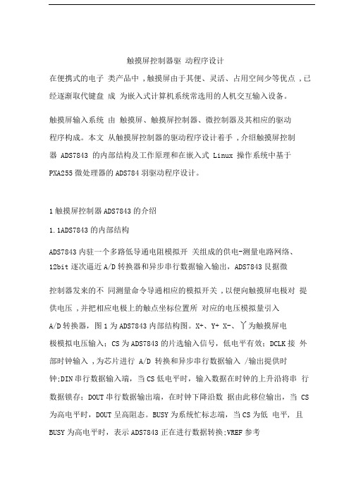
触摸屏控制器驱动程序设计在便携式的电子类产品中 ,触摸屏由于其便、灵活、占用空间少等优点 ,已经逐渐取代键盘成为嵌入式计算机系统常选用的人机交互输入设备。
触摸屏输入系统由触摸屏、触摸屏控制器、微控制器及其相应的驱动程序构成。
本文从触摸屏控制器的驱动程序设计着手 ,介绍触摸屏控制器 ADS7843 的内部结构及工作原理和在嵌入式 Linux 操作系统中基于PXA255微处理器的ADS784羽驱动程序设计。
1触摸屏控制器ADS7843的介绍1.1ADS7843的内部结构ADS7843内驻一个多路低导通电阻模拟开关组成的供电-测量电路网络、12bit逐次逼近A/D转换器和异步串行数据输入输出,ADS7843艮据微控制器发来的不同测量命令导通相应的模拟开关 ,以便向触摸屏电极对提供电压 ,并把相应电极上的触点坐标位置所对应的电压模拟量引入A/D转换器,图1为ADS7843内部结构图。
X+、Y+ X-、丫为触摸屏电极模拟电压输入;CS为ADS7843的片选输入信号,低电平有效;DCLK接外部时钟输入 ,为芯片进行 A/D 转换和异步串行数据输入 /输出提供时钟;DIN串行数据输入端,当CS低电平时,输入数据在时钟的上升沿将串行数据锁存;DOUT串行数据输出端,在时钟下降沿数据由此移位输出,当 CS 为高电平时,DOUT呈高阻态。
BUSY为系统忙标志端,当CS为低电平, 且BUSY为高电平时,表示ADS7843正在进行数据转换;VREF参考电压输入端,电压值在+1V到+VCC之间变化;PENIRC为笔触中断,低电平有效;IN3、IN4为辅助ADC转换输入通道;+VCC为电源输入。
图1ADS7843内部结构1.2ADS7843的转换时序ADS7843完成一次数据转换需要与微控制器进行3次通信,第一次微处理器通过异步数据传送向 ADS843 发送控制字 ,其中包括起始位、通道选择、 8/12 位模式、差分 /单端选择和掉电模式选择 ,其后的两次数据传送则是微控制器从 ADS7843 取出 16bitA/D 转换结果数据(最后四位自动补零),每次通信需要 8 个时钟周期 ,完成一次数据转换共需 24 个时钟周期周2为ADS7843转换时序。
ADS7843简介及应用

1
OUTLINE
1.ADS7843特性 2.ADS7843腳位定義 3.ADS7843方塊圖 4.ADS7843廠內之應用
2
1.ADS7843特性
a.4-WIRE T/P INTERFACE b.SINGLE SUPPLY:2.7V~5.0V c.SERIAL INTERFACE d.PROGRAMMABLE 8-OR 12-BIT RESOLUTION e.2 AUXILIARY ANALOG INPUTS
HandIN為讀取I18_Bit,ADS7843應用為8_Bit,試 問TFT Control Box上可變電阻在軟體上需 做幾階調的變化較適當?
2^8=256 可變化總階調 2^6=64 RGB各佔6_Bit 256/64=4 故軟體應做每調四階實際輸出變化一次較適當
開關 控制 腳
Out to control A/D 階數變化值
10
3. Timing characteristics diagram
11
Timing characteristics diagram SPI (System Interface)
D15 D14 D13 D12 D11 D10 D9 D8 D7 D6 D5 D4 D3 D2 D1 D0
6
4-WIRE T/P 動作原理
7
TOUCH PANEL軟體
int runTP(void) { while (PENIRQ); 中斷指令 Xdata=HandShack(scanX_comm); Ydata=HandShack(scanY_comm); if(((Xdata>=0x0ddd)&&(Xdata<=0x0fff))&&((Ydata>=0x0000)&&(Ydata<=0x0333))) return 1; else if(((Xdata>=0x0444)&&(Xdata<=0x0777))&&((Ydata>=0x0000)&&(Ydata<=0x0444))) return 2; else if(((Xdata>=0x0444)&&(Xdata<=0x0777))&&((Ydata>=0x0ccc)&&(Ydata<=0x0fff))) return 3; else if(((Xdata>=0x0ddd)&&(Xdata<=0x0fff))&&((Ydata>=0x0ddd)&&(Ydata<=0x0fff))) return 4; else if(((Xdata>=0x0555)&&(Xdata<=0x0aaa))&&((Ydata>=0x0555)&&(Ydata<=0x0aaa))) return 5; else return 0; } X+
ADS7844application

ADS7844串行模/数转换芯片的原理及其在嵌入式的应用12位高精度AD的使用ADS7844串行模/数转换芯片的原理及其在嵌入式的应用摘要:ADS7844是一种12-Bit的串行数模转换器芯片。
它具有与CPU方便联接的同步串行接口,接口灵活, 功耗低等特点。
文中详细介绍了ADS7844的工作原理、引脚定义、工作时序及同步串行模式下与51单片机的接口电路及部分读写程序以及需要注意的地方。
关键词:模数转换器 SPI接口 ADS7844 单片机概述A/D采集芯片在以单片机为核心构成的智能仪器仪表、测控系统、工业控制等领域中有着广泛影响。
但是现在有的A/D转换芯片存在着精度差和接口电路复杂等缺点。
ADS7844是Burr-Brown公司推出的一种高性能、宽电压、低功耗的可以程控为8通道单端输入或4通道差分端输入的12-Bit的串行数模转换器,内部集成有SPI口。
从而简化了接口电路设计,无需用复杂的外围元件,就可实现精度高、性能稳定的数据采集转换。
在5V电源,转换速率为200kHz的情况下功耗仅仅3Mw。
在节电模式下,功耗可以减小到1uW1、特性及引脚说明1〃1 ADS7844主要特性如下:①单电源,电压范围:2.7V-5V均能正常工作,最大工作电流为1mA,进入低功耗状态后的耗电仅3μA②其转换率高达200kHz③它有8个模拟输入端,可用软件编程为8通道单端输入A/D转换器或4通道差分输入A/D转换器④典型信噪比为72dB。
⑤积分非线性(INL)和差分非线性(DNL)最大为±0.5LSB⑥保证无漏码⑦SPI接口⑧采用20脚QSOP或SSOP封装形式。
1〃2 ADS7844引脚的功能和排列说明AD7844引脚功能说明如表1所示,引脚排列如图1所示表1引脚号引脚名称功能描述备注1、2、3、4、5、6、7、8 CH0-CH7模拟输入端。
器件被设置为单端输入时,这些引脚可分别与信号地COM构成8通道单端输入A/D转换器;当器件被设置为差分输入时,利用CH0~CH1、CH2~CH3、CH4~CH5和CH6~CH7可构成4通道差分输入A/D转换器 对状态寄存器的SGL/DIF位进行配置以设定输入模式。
ADS7843EG4中文资料

FEATURESq 4-WIRE TOUCH SCREEN INTERFACE q RATIOMETRIC CONVERSION q SINGLE SUPPLY: 2.7V to 5V q UP TO 125kHz CONVERSION RATE q SERIAL INTERFACEq PROGRAMMABLE 8- OR 12-BIT RESOLUTION q 2 AUXILIARY ANALOG INPUTS qFULL POWER-DOWN CONTROLDESCRIPTIONThe ADS7843 is a 12-bit sampling Analog-to-Digital Con-verter (ADC) with a synchronous serial interface and low on-resistance switches for driving touch screens. Typical power dissipation is 750µW at a 125kHz throughput rate and a +2.7V supply. The reference voltage (V REF ) can be varied between 1V and +V CC , providing a corresponding input voltage range of 0V to V REF . The device includes a shutdown mode which reduces typical power dissipation to under 0.5µW. The ADS7843 is specified down to 2.7V operation.Low power, high speed, and onboard switches make the ADS7843 ideal for battery-operated systems such as per-sonal digital assistants with resistive touch screens and other portable equipment. The ADS7843 is available in an SSOP-16 package and is specified over the –40°C to +85°C temperature range.APPLICATIONSq PERSONAL DIGITAL ASSISTANTS q PORTABLE INSTRUMENTS q POINT-OF-SALES TERMINALS q PAGERSqTOUCH SCREEN MONITORSTOUCH SCREEN CONTROLLERCSDIN DOUTBUSYDCLKX+PENIRQX –Y+Y –IN3IN4V REFADS7843SBAS090B – SEPTEMBER 2000 – REVISED MAY 2002PRODUCTION DATA information is current as of publication date.Products conform to specifications per the terms of Texas Instruments standard warranty. Production processing does not necessarily include testing of all parameters.Copyright © 2001, Texas Instruments IncorporatedPlease be aware that an important notice concerning availability, standard warranty, and use in critical applications of Texas Instruments semiconductor products and disclaimers thereto appears at the end of this data sheet.US Patent No. 6246394ADS78432SBAS090BPIN NAME DESCRIPTION1+V CC Power Supply, 2.7V to 5V.2X+X+ Position Input. ADC input Channel 1.3Y+Y+ Position Input. ADC input Channel 2.4X –X – Position Input 5Y –Y – Position Input 6GND Ground7IN3Auxiliary Input 1. ADC input Channel 3.8IN4Auxiliary Input 2. ADC input Channel 4.9V REF Voltage Reference Input 10+V CC Power Supply, 2.7V to 5V.11PENIRQ Pen Interrupt. Open anode output (requires 10k Ωto 100k Ω pull-up resistor externally).12DOUTSerial Data Output. Data is shifted on the falling edge of DCLK. This output is high impedance when CS is HIGH.13BUSY Busy Output. This output is high impedance when CS is HIGH.14DIN Serial Data Input. If CS is LOW, data is latched on rising edge of DCLK.15CS Chip Select Input. Controls conversion timing and enables the serial input/output register.16DCLKExternal Clock Input. This clock runs the SAR con-version process and synchronizes serial data I/O.ABSOLUTE MAXIMUM RATINGS (1)+V CC to GND ........................................................................–0.3V to +6V Analog Inputs to GND ............................................–0.3V to +V CC + 0.3V Digital Inputs to GND .............................................–0.3V to +V CC + 0.3V Power Dissipation..........................................................................250mW Maximum Junction Temperature...................................................+150°C Operating Temperature Range ........................................–40°C to +85°C Storage Temperature Range .........................................–65°C to +150°C Lead Temperature (soldering, 10s)...............................................+300°C NOTE: (1) Stresses above those listed under “Absolute Maximum Ratings ”may cause permanent damage to the device. Exposure to absolute maximum conditions for extended periods may affect device reliability.This integrated circuit can be damaged by ESD. Texas Instru-ments recommends that all integrated circuits be handled with appropriate precautions. Failure to observe proper handling and installation procedures can cause damage.ESD damage can range from subtle performance degradation to complete device failure. Precision integrated circuits may be more susceptible to damage because very small parametric changes could cause the device not to meet its published specifications.12345678+V CC X+Y+X –Y –GND IN3IN4DCLK CS DIN BUSY DOUT PENIRQ +V CC V REF161514131211109ADS7843PIN CONFIGURATIONTop ViewSSOPPIN DESCRIPTIONMAXIMUM INTEGRAL SPECIFIED LINEARITY PACKAGE TEMPERATUREPACKAGE ORDERING TRANSPORT PRODUCT ERROR (LSB)PACKAGE-LEADDESIGNATOR (1)RANGE MARKING NUMBER MEDIA, QUANTITY ADS7843E±2SSOP-16DBQ–40°C to +85°CADS7843E ADS7843E Rails, 100"""""ADS7843EADS7843E/2K5Tape and Reel, 2500NOTES: (1) For the most current specifications and package information, refer to our web site at .PACKAGE/ORDERING INFORMATIONADS78433SBAS090BPARAMETER CONDITIONSMIN TYPMAX UNITS ANALOG INPUTFull-Scale Input Span Positive Input – Negative Input0V REF V Absolute Input Range Positive Input –0.2+V CC +0.2V Negative Input–0.2+0.2V Capacitance 25pF Leakage Current0.1µA SYSTEM PERFORMANCE Resolution12Bits No Missing Codes 11Bits Integral Linearity Error ±2LSB (1)Offset Error±6LSB Offset Error Match 0.1 1.0LSB Gain Error±4LSB Gain Error Match 0.1 1.0LSB Noise30µVrms Power-Supply Rejection 70dB SAMPLING DYNAMICS Conversion Time 12Clk Cycles Acquisition Time 3Clk CyclesThroughput Rate125kHz Multiplexer Settling Time 500ns Aperture Delay 30ns Aperture Jitter100ps Channel-to-Channel Isolation V IN = 2.5Vp-p at 50kHz100dBSWITCH DRIVERS On-Resistance Y+, X+5ΩY –, X –6ΩREFERENCE INPUT Range 1.0+V CC V Resistance CS = GND or +V CC 5G ΩInput Current1340µA f SAMPLE = 12.5kHz2.5µA CS = +V CC0.0013µADIGITAL INPUT/OUTPUT Logic FamilyCMOSLogic Levels, Except PENIRQ V IH | I IH | ≤ +5µA +V CC • 0.7+V CC +0.3V IL | I IL | ≤ +5µA –0.3+0.8V V OH I OH = –250µA +V CC • 0.8V V OL I OL = 250µA0.4V PENIRQ V OLT A = 0°C to +85°C, 100k Ω Pull-Up0.8VData FormatStraight BinaryPOWER-SUPPLY REQUIREMENTS +V CCSpecified Performance 2.73.6V Quiescent Current280650µA f SAMPLE = 12.5kHz 220µA Shutdown Mode with 3µA DCLK = DIN = +V CCPower Dissipation +V CC = +2.7V1.8mW TEMPERATURE RANGE Specified Performance–40+85°CELECTRICAL CHARACTERISTICSAt T A = –40°C to +85°C, +V CC = +2.7V, V REF = +2.5V, f SAMPLE = 125kHz, f CLK = 16 • f SAMPLE = 2MHz, 12-bit mode, and digital inputs = GND or +V CC , unless otherwise noted.ADS7843ENOTE: (1) LSB means Least Significant Bit. With V REF equal to +2.5V, 1LSB is 610µV.ADS78434SBAS090BTYPICAL CHARACTERISTICSAt T A = +25°C, +V CC = +2.7V, V REF = +2.5V, f SAMPLE = 125kHz, and f CLK = 16 • f SAMPLE = 2MHz, unless otherwise noted.SUPPLY CURRENT vs +V CC3.5252.54+V CC (V)S u p p l y C u r r e n t (µA )3203002802602402202001804.53MAXIMUM SAMPLE RATE vs +V CC3.5252.54+V CC (V)S a m p l e R a t e (H z )1M100k10k1k4.53SUPPLY CURRENT vs TEMPERATURE20–40100–2040Temperature (°C)S u p p l y C u r r e n t (µA )4003503002502001501006080CHANGE IN GAIN vs TEMPERATURE20–40100–2040Temperature (°C)D e l t a f r o m +25˚C (L S B )0.150.100.050.00–0.05–0.10–0.156080CHANGE IN OFFSET vs TEMPERATURE20–40100–2040Temperature (°C)D e l t a f r o m +25˚C (L S B )0.60.40.20.0–0.2–0.4–0.66080POWER-DOWN SUPPLY CURRENTvs TEMPERATURE20–40100–2040Temperature (°C)S u p p l y C u r r e n t (n A )140120100806040206080ADS78435SBAS090BTYPICAL CHARACTERISTICS (Cont.)At T A = +25°C, +V CC = +2.7V, V REF = +2.5V, f SAMPLE = 125kHz, and f CLK = 16 • f SAMPLE= 2MHz, unless otherwise noted.REFERENCE CURRENT vs SAMPLE RATE751252550100Sample Rate (kHz)R e f e r e n c e C u r r e n t (µA )14121086420REFERENCE CURRENT vs TEMPERATURE20–40100–2040Temperature (°C)R e f e r e n c e C u r r e n t (µA )1816141210866080SWITCH-ON RESISTANCE vs +V CC (X+, Y+: +V CC to Pin; X –, Y –: Pin to GND)3.5252.54+V CC (V)R O N (Ω)18765432 4.53SWITCH-ON RESISTANCE vs TEMPERATURE (X+, Y+: +V CC to Pin; X –, Y –: Pin to GND)20–40100–2040Temperature (°C)R O N (Ω)18765432608021.81.61.41.210.80.60.40.20L S B E r r o r20406080100120140160180200Sampling Rate (kHz)MAXIMUM SAMPLING RATE vs RINTHEORY OF OPERATIONThe ADS7843 is a classic Successive Approximation Regis-ter (SAR) ADC. The architecture is based on capacitive redistribution which inherently includes a sample-and-hold function. The converter is fabricated on a 0.6µs CMOS process.The basic operation of the ADS7843 is shown in Figure 1. The device requires an external reference and an external clock. It operates from a single supply of 2.7V to 5.25V. The external reference can be any voltage between 1V and +V CC. The value of the reference voltage directly sets the input range of the converter. The average reference input current depends on the conversion rate of the ADS7843.The analog input to the converter is provided via a four-channel multiplexer. A unique configuration of low on-resis-tance switches allows an unselected ADC input channel to provide power and an accompanying pin to provide ground for an external device. By maintaining a differential input to the converter and a differential reference architecture, it is pos-sible to negate the switch’s on-resistance error (should this be a source of error for the particular measurement).ANALOG INPUTSee Figure 2 for a block diagram of the input multiplexer on the ADS7843, the differential input of the ADC, and the converter’s differential reference. Table I and Table II show the relation-ship between the A2, A1, A0, and SER/DFR control bits and the configuration of the ADS7843. The control bits are pro-vided serially via the DIN pin—see the Digital Interface section of this data sheet for more details.When the converter enters the hold mode, the voltage difference between the +IN and –IN inputs (see Figure 2) is captured on the internal capacitor array. The input current on the analog inputs depends on the conversion rate of the device. During the sample period, the source must charge the internal sampling capacitor (typically 25pF). After the capacitor has been fully charged, there is no further input current. The rate of charge transfer from the analog source to the converter is a function of conversion rate.TABLE I. Input Configuration, Single-Ended Reference Mode (SER/DFR HIGH).NOTE: (1) Internal node, for clarification only—not directly accessible by the user.A2A1A0X+Y+IN3IN4–IN(1)X SWITCHES Y SWITCHES+REF(1)–REF(1) 001+IN–Y OFF ON+Y–Y 101+IN–X ON OFF+X–X 010+IN GND OFF OFF+V REF GND 110+IN GND OFF OFF+V REF GND NOTE: (1) Internal node, for clarification only—not directly accessible by the user.TABLE II. Input Configuration, Differential Reference Mode (SER/ LOW).ADS7843 6SBAS090BFIGURE 2. Simplified Diagram of Analog Input.REFERENCE INPUTThe voltage difference between +REF and –REF (shown in Figure 2) sets the analog input range. The ADS7843 will operate with a reference in the range of 1V to +V CC. There are several critical items concerning the reference input and its wide voltage range. As the reference voltage is reduced, the analog voltage weight of each digital output code is also reduced. This is often referred to as the LSB (least significant bit) size and is equal to the reference voltage divided by 4096. Any offset or gain error inherent in the ADC will appear to increase, in terms of LSB size, as the reference voltage is reduced. For example, if the offset of a given converter is 2LSBs with a 2.5V reference, it will typically be 5LSBs with a 1V reference. In each case, the actual offset of the device is the same, 1.22mV. With a lower reference voltage, more care must be taken to provide a clean layout including adequate bypassing, a clean (low noise, low ripple) power supply, a low-noise reference, and a low-noise input signal.The voltage into the V REF input is not buffered and directly drives the Capacitor Digital-to-Analog Converter (CDAC) por-tion of the ADS7843. Typically, the input current is 13µA with V REF = 2.7V and f SAMPLE = 125kHz. This value will vary by a few microamps depending on the result of the conversion. The reference current diminishes directly with both conversion rate and reference voltage. As the current from the reference is drawn on each bit decision, clocking the converter more quickly during a given conversion period will not reduce overall current drain from the reference.There is also a critical item regarding the reference when making measurements where the switch drivers are on. For this discussion, it’s useful to consider the basic operation of the ADS7843 as shown in Figure 1. This particular applica-tion shows the device being used to digitize a resistive touch screen. A measurement of the current Y position of the pointing device is made by connecting the X+ input to the ADC, turning on the Y+ and Y– drivers, and digitizing the voltage on X+ (shown in Figure 3). For this measurement, the resistance in the X+ lead does not affect the conversion (it does affect the settling time, but the resistance is usually small enough that this is not a concern).FIGURE 3.Simplified Diagram of Single-Ended Reference (SER/DFR HIGH, Y Switches Enabled, X+ isAnalog Input).ADS78437 SBAS090B ADS78438SBAS090BFIGURE 5. Conversion Timing, 24 Clocks per Conversion, 8-bit Bus Interface. No DCLK Delay Required with DedicatedSerial Port.However, since the resistance between Y+ and Y – is fairly low,the on-resistance of the Y drivers does make a small differ-ence. Under the situation outlined so far, it would not be possible to achieve a 0V input or a full-scale input regardless of where the pointing device is on the touch screen because some voltage is lost across the internal switches. In addition,the internal switch resistance is unlikely to track the resistance of the touch screen, providing an additional source of error.This situation can be remedied as shown in Figure 4. By setting the SER/DFR bit LOW, the +REF and –REF inputs are connected directly to Y+ and Y –. This makes the A/D conver-sion ratiometric. The result of the conversion is always a percentage of the external resistance, regardless of how it changes in relation to the on-resistance of the internalFIGURE 4. Simplified Diagram of Differential Reference (SER/DFR LOW, Y Switches Enabled, X+ is Analog Input).switches. Note that there is an important consideration regard-ing power dissipation when using the ratiometric mode of operation, see the Power Dissipation section for more details.As a final note about the differential reference mode, it must be used with +V CC as the source of the +REF voltage and cannot be used with V REF . It is possible to use a high precision reference on V REF and single-ended reference mode for mea-surements which do not need to be ratiometric. Or, in some cases, it could be possible to power the converter directly from a precision reference. Most references can provide enough power for the ADS7843, but they might not be able to supply enough current for the external load (such as a resistive touch screen).DIGITAL INTERFACEFigure 5 shows the typical operation of the ADS7843’s digital interface. This diagram assumes that the source of the digital signals is a microcontroller or digital signal processor with a basic serial interface. Each communication between the pro-cessor and the converter consists of eight clock cycles. One complete conversion can be accomplished with three serial communications, for a total of 24 clock cycles on the DCLK input.The first eight clock cycles are used to provide the control byte via the DIN pin. When the converter has enough information about the following conversion to set the input multiplexer,switches, and reference inputs appropriately, the converter enters the acquisition (sample) mode and, if needed, the internal switches are turned on. After three more clock cycles,the control byte is complete and the converter enters the conversion mode. At this point, the input sample-and-hold goes into the hold mode and the internal switches may turn off. TheADS78439SBAS090B1DCLKCS8111DOUT BUSYSDIN CONTROL BITSSCONTROL BITS109876543210111098118next 12th clock cycles accomplish the actual A/D conversion.If the conversion is ratiometric (SER/DFR LOW), the internal switches are on during the conversion. A 13th clock cycle is needed for the last bit of the conversion result. Three more clock cycles are needed to complete the last byte (DOUT will be LOW). These will be ignored by the converter.Control ByteSee Figure 5 for the placement and order of the control bits within the control byte. Tables III and IV give detailed informa-tion about these bits. The first bit, the ‘S ’ bit, must always be HIGH and indicates the start of the control byte. The ADS7843will ignore inputs on the DIN pin until the start bit is detected.The next three bits (A2-A0) select the active input channel or channels of the input multiplexer (see Tables I and II and Figure 2). The MODE bit determines the number of bits for each conversion, either 12 bits (LOW) or 8 bits (HIGH).The SER/DFR bit controls the reference mode: either single-ended (HIGH) or differential (LOW). (The differential mode is also referred to as the ratiometric conversion mode.) In single-ended mode, the converter ’s reference voltage is always the difference between the V REF and GND pins. In differential mode, the reference voltage is the difference between the currently enabled switches. See Tables I and II and Figures 2through 4 for more information. The last two bits (PD1-PD0)select the power-down mode as shown in Table V. If both inputs are HIGH, the device is always powered up. If both inputs are LOW, the device enters a power-down mode between conversions. When a new conversion is initiated, the device will resume normal operation instantly —no delay is needed to allow the device to power up and the very first conversion will be valid. There are two power-down modes:one where PENIRQ is disabled and one where it is enabled.PD1PD0PENIRQ DESCRIPTIONEnabledPower-down between conversions. When each conversion is finished, the converter enters a low power mode. At the start of the next conversion,the device instantly powers up to full power.There is no need for additional delays to assure full operation and the very first conversion is valid. The Y – switch is on while in power-down.01Disabled Same as mode 00, except PENIRQ is disabled.The Y – switch is off while in power-down mode.10Disabled Reserved for future use.11DisabledNo power-down between conversions, device is always powered.TABLE V. Power-Down Selection.FIGURE 6. Conversion Timing, 16 Clocks per Conversion, 8-bit Bus Interface. No DCLK Delay Required with DedicatedSerial Port.BIT NAME DESCRIPTION7SStart Bit. Control byte starts with first HIGH bit on DIN. A new control byte can start every 16th clock cycle in 12-bit conversion mode or every 12th clock cycle in 8-bit conversion mode.6-4A2-A0Channel Select Bits. Along with the SER/DFR bit,these bits control the setting of the multiplexer input,switches, and reference inputs, see Tables I and II.3MODE12-Bit/8-Bit Conversion Select Bit. This bit controls the number of bits for the following conversion: 12bits (LOW) or 8 bits (HIGH).2 SER/DFRSingle-Ended/Differential Reference Select Bit. Along with bits A2-A0, this bit controls the setting of the multiplexer input, switches, and reference inputs, see Tables I and II.1-0PD1-PD0Power-Down Mode Select Bits. See Table V for details.TABLE IV. Descriptions of the Control Bits within the ControlByte.Bit 7Bit 6Bit 5Bit 4Bit 3Bit 2Bit 1Bit 0(MSB)(LSB)SA2A1A0MODE SER/DFRPD1PD0TABLE III. Order of the Control Bits in the Control Byte.16-Clocks per ConversionThe control bits for conversion n + 1 can be overlapped with conversion ‘n ’ to allow for a conversion every 16 clock cycles,as shown in Figure 6. This figure also shows possible serial communication occurring with other serial peripherals between each byte transfer between the processor and the converter.ADS784310SBAS090BFIGURE 8. Ideal Input Voltages and Output Codes.This is possible provided that each conversion completes within 1.6ms of starting. Otherwise, the signal that has been captured on the input sample-and-hold may droop enough to affect the conversion result. Note that the ADS7843 is fully powered while other serial communications are taking place during a conversion.Digital TimingFigure 7 and Table VI provide detailed timing for the digital interface of the ADS7843.SYMBOL DESCRIPTION MIN TYPMAXUNITS t ACQ Acquisition Time1.5µs t DS DIN Valid Prior to DCLK Rising 100ns t DH DIN Hold After DCLK HIGH 10ns t DO DCLK Falling to DOUT Valid 200ns t DV CS Falling to DOUT Enabled 200ns t TR CS Rising to DOUT Disabled 200ns t CSS CS Falling to First DCLK Rising 100ns t CSH CS Rising to DCLK Ignored0ns t CH DCLK HIGH 200ns t CL DCLK LOW200ns t BD DCLK Falling to BUSY Rising 200ns t BDV CS Falling to BUSY Enabled 200ns t BTRCS Rising to BUSY Disabled200nsTABLE VI. Timing Specifications (+V CC = +2.7V and Above,T A = –40°C to +85°C, C LOAD = 50pF).FIGURE 7. Detailed Timing Diagram.Data FormatThe ADS7843 output data is in Straight Binary format, as shown in Figure 8. This figure shows the ideal output code for the given input voltage and does not include the effects of offset, gain, or noise.8-Bit ConversionThe ADS7843 provides an 8-bit conversion mode that can be used when faster throughput is needed and the digital result is not as critical. By switching to the 8-bit mode, a conversion is complete four clock cycles earlier. This could be used in conjunction with serial interfaces that provide 12-bit transfers or two conversions could be accomplished with three 8-bit transfers. Not only does this shorten each conversion by four bits (25% faster throughput), but each conversion can actu-ally occur at a faster clock rate. This is because the internal settling time of the ADS7843 is not as critical —settling to better than 8 bits is all that is needed. The clock rate can be as much as 50% faster. The faster clock rate and fewer clock cycles combine to provide a 2x increase in conversion rate.POWER DISSIPATIONThere are two major power modes for the ADS7843: full power (PD1-PD0 = 11B ) and auto power-down (PD1-PD0 = 00B ).When operating at full speed and 16 clocks per conversion ( see Figure 6), the ADS7843 spends most of its time acquiring or converting. There is little time for auto power-down, assuming that this mode is active. Therefore, the difference between full power mode and auto power-down is negligible. If the conver-sion rate is decreased by simply slowing the frequency of the DCLK input, the two modes remain approximately equal. How-ever, if the DCLK frequency is kept at the maximum rate during a conversion but conversions are simply done less often, the difference between the two modes is dramatic.Figure 9 shows the difference between reducing the DCLK frequency (“scaling ” DCLK to match the conversion rate) or maintaining DCLK at the highest frequency and reducing the number of conversions per second. In the later case, the converter spends an increasing percentage of its time in power-down mode (assuming the auto power-down mode is active).Another important consideration for power dissipation is the reference mode of the converter. In the single-ended refer-ence mode, the converter ’s internal switches are on only when the analog input voltage is being acquired (see Figure 5). Thus, the external device, such as a resistive touch screen, is only powered during the acquisition period. In the differential reference mode, the external device must be powered throughout the acquisition and conversion periods (see Figure 5). If the conversion rate is high, this could substantially increase power dissipation.devices have fairly “clean ” power and grounds because most of the internal components are very low power. This situation would mean less bypassing for the converter ’s power and less concern regarding grounding. Still, each situation is unique and the following suggestions should be reviewed carefully.For optimum performance, care should be taken with the physical layout of the ADS7843 circuitry. The basic SAR architecture is sensitive to glitches or sudden changes on the power supply, reference, ground connections, and digital inputs that occur just prior to latching the output of the analog comparator. Thus, during any single conversion for an ‘n-bit ’SAR converter, there are n ‘windows ’ in which large external transient voltages can easily affect the conversion result.Such glitches might originate from switching power supplies,nearby digital logic, and high-power devices. The degree of error in the digital output depends on the reference voltage,layout, and the exact timing of the external event. The error can change if the external event changes in time with respect to the DCLK input.With this in mind, power to the ADS7843 should be clean and well bypassed. A 0.1µF ceramic bypass capacitor should be placed as close to the device as possible. A 1µF to 10µF capacitor may also be needed if the impedance of the connection between +V CC and the power supply is high.The reference should be similarly bypassed with a 0.1µF capacitor. If the reference voltage originates from an op amp,make sure that it can drive the bypass capacitor without oscillation. The ADS7843 draws very little current from the reference on average, but it does place larger demands on the reference circuitry over short periods of time (on each rising edge of DCLK during a conversion).The ADS7843 architecture offers no inherent rejection of noise or voltage variation in regards to the reference input.This is of particular concern when the reference input is tied to the power supply. Any noise and ripple from the supply will appear directly in the digital results. While high frequency noise can be filtered out, voltage variation due to line fre-quency (50Hz or 60Hz) can be difficult to remove.The GND pin should be connected to a clean ground point.In many cases, this will be the “analog ” ground. Avoid connections which are too near the grounding point of a microcontroller or digital signal processor. If needed, run a ground trace directly from the converter to the power-supply entry or battery connection point. The ideal layout will include an analog ground plane dedicated to the converter and associated analog circuitry.In the specific case of use with a resistive touch screen, care should be taken with the connection between the converter and the touch screen. Since resistive touch screens have fairly low resistance, the interconnection should be as short and robust as possible. Longer connections will be a source of error, much like the on-resistance of the internal switches.Likewise, loose connections can be a source of error when the contact resistance changes with flexing or vibrations.FIGURE 9. Supply Current versus Directly Scaling the Fre-quency of DCLK with Sample Rate or Keeping DCLK at the Maximum Possible Frequency.LAYOUTThe following layout suggestions should provide the most optimum performance from the ADS7843. However, many portable applications have conflicting requirements concern-ing power, cost, size, and weight. In general, most portable元器件交易网。
触摸屏控制芯片ADS中文资料

触摸屏控制芯片ADS中文资料随着科技的日新月异,触摸屏已经成为我们生活中不可或缺的一部分。
而实现触摸屏功能的核心设备就是触摸屏控制芯片(Touch Screen Controller)。
其中,由美国德州仪器(Texas Instruments)公司出品的ADS触摸屏控制器,因其高效、稳定等特点广受好评。
本文将介绍关于ADS触摸屏控制芯片的中文资料,以帮助读者更好地了解和应用。
一、ADS触摸屏控制芯片的基本介绍ADS是DeTexAS(德州仪器)电容式触摸屏控制芯片,是一款高性能和低功耗的控制芯片,用于对电容式触摸屏的数据采集和处理。
其主要优点包括:1.高精度采集:ADS可以在高灵敏度、高准确度的状态下,快速采集有关电容式触摸屏各种触摸信息。
可支持4线、5线电阻式触摸屏以及电容式触摸屏。
2.强大的报告处理:ADS的报告率可达200Hz,符合市场上各种不同需求的触摸屏设备。
3.低功耗:ADS的低功耗设计可最大程度延长设备的电池续航能力。
除此之外,ADS还融入了多种先进的电路设计技术,如多点触控、自动进入低功耗模式、广泛的温度范围和高速传输技术,保证了它在功能方面的完备性以及出色的性能表现。
二、ADS触摸屏控制芯片的应用场景ADS广泛应用于智能手机、平板电脑、护航摄影、手持终端和医疗设备等领域,在其中扮演了非常重要的角色。
在智能手机和平板电脑市场,例如三星S6,华为P9和苹果iPhone,都采用了德州仪器的ADS控制器来实现更加完美的触摸体验。
同时,ADS还被广泛应用于工业自动化、家庭娱乐等领域。
三、ADS触摸屏控制芯片相关中文资料随着ADS触摸屏控制芯片的逐渐普及和应用,越来越多的人希望了解该芯片的相关资料。
以下是几种常见的中文资料:1. ADS芯片数据手册ADS芯片数据手册是一份详细的技术文档,可以提供ADS触摸屏控制芯片各项技术指标、功能及接口的详细描述。
此外,数据手册还包含了ADS的软件和硬件架构方案,以及使用提示和设计建议。
基于ILI9320和ADS7843的触摸显示屏控制系统设计

基于ILI9320和ADS7843的触摸显示屏控制系统设计陈章宝;邓运生【摘要】Medium and small touch and display screen was widely used in portable network terminal,and it gave the design in this paper of 2.8 inch TFT-LCD touch and display screen module,design of circuit withSTC12C5A60S2 as main chip,system includes display screen and touch screen interface circuit,FPC interface circuit,SD card interface circuit,and the driving program and application program design method were given.The experimental results showed that the system is stable and all the functions are realized.%结合中小型触摸显示屏在手持式网络终端中的广泛应用,给出了一种2.8寸TFT-LCD触摸显示屏模块的设计方法,以STC12C5A60S2为主控芯片,包括显示屏和触摸屏接口电路、FPC接口电路、SD卡接口电路等,给出驱动程序及其应用程序的设计方法.实验结果表明,系统运行稳定,能够实现模块的全部功能.【期刊名称】《蚌埠学院学报》【年(卷),期】2017(006)002【总页数】5页(P12-16)【关键词】显示触摸屏;薄膜场效应晶体管显示器;驱动程序【作者】陈章宝;邓运生【作者单位】蚌埠学院电子与电气工程学院,安徽蚌埠 233030;蚌埠学院电子与电气工程学院,安徽蚌埠 233030【正文语种】中文【中图分类】TP274随着电子信息技术的发展,平面显示技术被广泛应用于日常的生产和生活当中,而液晶显示(LCD:Liquid Crystal Display)器件由于具有功耗低、重量轻、价格低以及优越的字符和图形显示功能,在智能仪器仪表、手持网络设备、物联网终端设备中得到了广泛的应用。
基于ILI9320和ADS7843的触摸显示屏控制系统设计
到了 广 泛 的 应 用。 中小 型 显 示 屏 主要 有 T F T 、 O L E D、 U F B显 示 屏 等 , T F T — L C D( T h i n F i l m T r a n . s i s t o r — L C D 即薄 膜 场 效 应 晶体 管 显 示 器 ) 属 于有 源
中图 分 类 号 : T P 2 7 4 文献标识码 : A 文章编号 : ( 2 0 1 7 ) 0 2— 0 0 1 2— 0 5
- 1、下载文档前请自行甄别文档内容的完整性,平台不提供额外的编辑、内容补充、找答案等附加服务。
- 2、"仅部分预览"的文档,不可在线预览部分如存在完整性等问题,可反馈申请退款(可完整预览的文档不适用该条件!)。
- 3、如文档侵犯您的权益,请联系客服反馈,我们会尽快为您处理(人工客服工作时间:9:00-18:30)。
触摸屏控制芯片ADS7843中文资料ADS7843是一个内置12位模数转换、低导通电阻模拟开关的串行接口芯片。
供电电压 2.7~5 V,参考电压VREF为 1 V~+VCC,转换电压的输入范围为0~ VREF,最高转换速率为125 kHz。
ADS7843引脚图及引脚功能说明了:ADS7843的引脚配置如图3所示。
表1为引脚功能说明,图4为典型应用。
aDS7843引脚说明ADS7843典型应用电路2.2 ADS7843的内部结构及参考电压模式选择ADS7843之所以能实现对触摸屏的控制,是因为其内部结构很容易实现电极电压的切换,并能进行快速A/D转换。
图5所示为其内部结构,A2~A0和SER/为控制寄存器中的控制位,用来进行开关切换和参考电压的选择。
ADS7843支持两种参考电压输入模式:一种是参考电压固定为VREF,另一种采取差动模式,参考电压来自驱动电极。
这两种模式分别如图6(a)、(b)所示。
采用图6(b)的差动模式可以消除开关导通压降带来的影响。
表2和表3为两种参考电压输入模式所对应的内部开关状况。
2.3 ADS7843的控制字及数据传输格式ADS7843的控制字如表4所列,其中S为数据传输起始标志位,该位必为"1"。
A2~A0进行通道选择(见表2和3)。
MODE用来选择A/D转换的精度,"1"选择8位,"0"选择12位。
SER/选择参考电压的输入模式(见表2和3)。
PD1、PD0选择省电模式:"00"省电模式允许,在两次A/D转换之间掉电,且中断允许;"01"同"00",只是不允许中断;"10"保留;"11"禁止省电模式。
为了完成一次电极电压切换和A/D转换,需要先通过串口往ADS7843发送控制字,转换完成后再通过串口读出电压转换值。
标准的一次转换需要24个时钟周期,如图7所示。
由于串口支持双向同时进行传送,并且在一次读数与下一次发控制字之间可以重叠,所以转换速率可以提高到每次16个时钟周期,如图8所示。
如果条件允许,CPU可以产生15个CLK的话(比如FPGAs和ASICs),转换速率还可以提高到每次15个时钟周期,如图9所示。
2.4 A/D转换时序的程序设计ADS7843的典型应用如图4所示。
假设μP接口与51单片机的P1.3~P1.7相连,现以一次转换需24个时钟周期为例,介绍A/D转换时序的程序设计。
; A/D 接口控制线DCLK BIT P1.3CS BIT P1.4DIN BIT P1.5BUSY BIT P1.6DOUT BIT P1.7; A/D 通道选择命令字和工作寄存器CHX EQU 094H ;通道X+的选择控制字CHY EQU 0D4H;通道Y+的选择控制字CH3 EQU 0A4HCH4 EQU 0E4HAD_CH EQU 35H ;通道选择寄存器AD_RESULTH EQU 36H ;存放12 bit A/D值AD_RESULTL EQU 37H; 存放通道CHX+的A/D值CHXAdResultH EQU 38HCHXAdResultL EQU 39H; 存放通道CHY+的A/D值CHY AdResultH EQU 3AHCHY AdResultL EQU 3BH; 采集通道CHX+的程序段(CHXAD) CHXAD: MOV AD_CH,#CHXLCALL AD_RUNMOV CHXAdResultH,AD_RESULTH MOV CHXAdResultL,AD_RESULTL RET; 采集通道CHY+的程序段(CHY AD) CHY AD: MOV AD_CH,#CHY LCALL AD_RUNMOV CHY AdResultH,AD_RESULTH MOV CHY AdResultL,AD_RESULTL RET; A/D转换子程序(AD_RUN); 输入: AD_CH-模式和通道选择命令字; 输出: AD_RESULTH,L ;12 bit的A/D转换值; 使用: R2 ;辅助工作寄存器AD_RUN:CLR CS ; 芯片允许CLR DCLKMOV R2,#8 ;先写8 bit命令字MOV A,AD_CHAD_LOOP:MOV C, ACC.7MOV DIN,C ;时钟上升沿锁存DINSETB DCLK ;开始发送命令字CLR DCLK ;时钟脉冲,一共24个RL ADJNZ R2,AD_LOOPNOPNOPNOPNOPADW0: JNB BUSY,AD_W AIT ;等待转换完成SJMP ADW1AD_W AIT:LCALL W ATCHDOGNOPSJMP ADW0CLR DINADW1: MOV R2,#12 ;开始读取12bit结果SETB DCLKCLR DCLKAD_READ:SETB DCLKCLR DCLK ;用时钟的下降沿读取MOV A,AD_RESULTLMOV C,DOUTRLC AMOV AD_RESULTL,AMOV A,AD_RESULTHRLC AMOV AD_RESULTH,ADJNZ R2,AD_READMOV R2,#4 ;最后是没用的4个时钟IGNORE:SETB DCLKCLR DCLKDJNZ R2,IGNORESETB CS ;禁止芯片ANL AD_RESULTH,#0FH ;屏蔽高4 bitRET2.5 A/D转换结果的数据格式ADS7843转换结果为二进制格式。
需要说明的是,在进行公式计算时,参考电压在两种输入模式中是不一样的。
而且,如果选取8位的转换精度,1LSB=VREF/256,一次转换完成时间可以提前4个时钟周期,此时串口时钟速率也可以提高一倍。
本文来自: 原文网址:/info/commonIC/0086705.htmlADS7843驱动程序(C语言源程序)ADS7843是一个内置12位模数转换、低导通电阻模拟开关的串行接口芯片。
供电电压2.7~5 V,参考电压VREF为1 V~+VCC,转换电压的输入范围为0~ VREF,最高转换速率为125 kHz。
//===================================================================== // ADS7843 驱动程序(串行)//硬件连接: DCLK ——P0^0;// CS ——P0^1;// DIN ——P0^2;// BUSY——P0^3// DOUT ——P0^4// PENIRQ——P3^2;// VDD--逻辑电源(+5V)// VSS--GND(0V)//ADS7843.c//writer:谷雨2008年7月23日于EDA实验室//=====================================================================#include //STC单片机头文件#include#define uint unsigned int#define uchar unsigned charsbit DCLK = P0^0; //时钟信号,下降沿有效sbit CS = P0^1; //片选信号,低电平有效sbit DIN = P0^2; //串行数据输入sbit BUSY= P0^3; //忙信号sbit DOUT = P0^4; //串行数据输出sbit PENIRQ = P3^2; //键盘中断请求信号,低电平(负边沿)有效void Tranfer(char Data);uint average(uint a[8]);//===================================================================== ===============//函数名称:void delay(uint us)//函数功能:延时子函数//入口参数:us 延时时间//出口参数:无//===================================================================== ===============void delay(uint us){while(us--);}===============//函数名称:void ADS7843_start(void)//函数功能:ADS7843启动//入口参数:无//出口参数:无//===================================================================== ===============void ADS7843_start(void){DCLK=0;CS=1;DIN=1;DCLK=1;CS=0;}//===================================================================== ===============//函数名称:void ADS7843_wr(uchar dat)//函数功能:写ADS7843//入口参数:dat 写入的数据//出口参数:无//===================================================================== ===============void ADS7843_wr(uchar dat){uchar count;DCLK=0;for(count=0;count<8;count++){dat<<=1;DIN=CY;DCLK=0;_nop_();_nop_();_nop_();DCLK=1;_nop_();_nop_();_nop_();}}===============//函数名称:uint ADS7843_rd(void)//函数功能:读ADS7843//入口参数:无//出口参数:读回的坐标值//===================================================================== ===============uint ADS7843_rd(void){uchar count=0;uint dat=0;for(count=0;count<12;count++){dat<<=1;DCLK=1; _nop_();_nop_();_nop_(); //下降沿有效DCLK=0; _nop_();_nop_();_nop_();if(DOUT)dat++;}return(dat);}//===================================================================== ===============//函数名称:void intr0_int()//函数功能:外中断0中断服务函数//入口参数:无//出口参数:无//===================================================================== ===============void intr0_int() interrupt 0 using 2{uint X=0,Y=0,a[4],i, avex,avey,x[8],y[8];IE=0; //关中断delay(100); //中断后延时以消除抖动,使得采样数据更准确if(!PENIRQ){for(i=0;i<8;i++) //进行8次数据采集{ADS7843_start();delay(2);ADS7843_wr(0x90);//送控制字10010000 即用差分方式读X坐标delay(2);DCLK=1;_nop_();_nop_();_nop_();_nop_();DCLK=0;_nop_();_nop_();_nop_();_nop_();X=ADS7843_rd(); //读X轴坐标x[i]=X;ADS7843_wr(0xD0); //送控制字11010000 即用差分方式读Y坐标DCLK=1;_nop_();_nop_();_nop_();_nop_();DCLK=0;_nop_();_nop_();_nop_();_nop_();Y=ADS7843_rd(); //读Y轴坐标y[i]=Y;CS=1;}avex=average(x); //X坐标数据处理a[0]=avex/1000; //发上位机观察结果a[1]=(avex-a[0]*1000)/100;a[2]=(avex-a[0]*1000-a[1]*100)/10;a[3]=avex%10;Tranfer(a[0]+48);Tranfer(a[1]+48);Tranfer(a[2]+48);Tranfer(a[3]+48);avey=average(y); //Y坐标数据处理a[0]=avey/1000; //发上位机观察结果a[1]=(avey-a[0]*1000)/100;a[2]=(avey-a[0]*1000-a[1]*100)/10;a[3]=avey%10;Tranfer(a[0]+48);Tranfer(a[1]+48);Tranfer(a[2]+48);Tranfer(a[3]+48);for(i=0;i<10;i++) //延时,在程序中根据具体情况改动delay(10000);}IE=0x81; //开中断}//===================================================================== ===============//函数名称:void init_serial()//函数功能:初始化串口//入口参数:无//出口参数:无//===================================================================== ===============void init_serial(){TMOD=0x22; //定时器T1使用工作方式2TH1=250; //设置初值TL1=250;TR1=1; //开始计时PCON=0x80; //SMOD=1;SCON=0x50; //工作方式1,波特率9600bit/s,允许接收TI=1;}//===================================================================== ===============//函数名称:void Tranfer(char Data)//函数功能:发送数据程序//入口参数:Data 要发送的数据//出口参数:无//===================================================================== ===============void Tranfer(char Data){while(TI==0);SBUF=Data;TI=0;}//===================================================================== ===============//函数名称:int main()//函数功能:主函数//入口参数:无//出口参数:无//===================================================================== ===============int main(){// uint b[4];TCON=0x01; //设置外部中断0下降沿触发EX0=1; //开外中断0EA=1; //开总中断init_serial();while(1);}//===================================================================== ===============//函数名称:uint average(uint a[8])//函数功能:数据处理程序,采集8次的数据,去掉最大值,去掉最小值,然后求平均//入口参数:数组首地址//出口参数:平均值//===================================================================== ===============uint average(uint a[8]){uint max,min,i,ave=0,sum=0;max=a[0];min=a[0];for(i=0;i<8;i++){if(maxif(min>a[i])min=a[i];sum+=a[i];}ave=(sum-min-max)/6;return ave;}本文来自: 原文网址:/mcu/c51src/0086707.html。