多功能温度计说明书
kt300温度计使用说明书

kt300温度计使用说明书1、测量额温保持探头盖盖上,将红外探头对准额头部位,并将距离保持在3cm以内,轻按一下测量键即可开始测量,伴随蜂鸣声响约1秒后,测量成功,屏幕显示读数。
建议多测量几次,待测量值稳定,即最接近正确的体温。
注意:◎如果额头区域沾有头发,汗水或灰尘,请在使用前清洁该区域以提高读取精度◎经常检查探头是否清洁2、测量耳温取下探头盖,将红外探头轻轻插入耳道,轻按一下测量键“”,即可开始测量,伴随蜂鸣声响约1秒后,测量成功,屏幕显示读数。
注意:1岁以下儿童,测量时将耳朵轻柔向后拉,使耳道变直。
1岁以上儿童及成人,将耳朵轻柔向上并向后拉,使耳道变直。
注意:◎确保耳道清洁,没有耳垢或阻塞物◎右耳的测量结果可能与左耳有差别,若需反复测量,请测量同一侧耳朵温度◎不要强迫进入耳道,否则,耳道可能会有损伤3.测量物温当体温计处于关机状态时,长按记忆/静音键,3秒以上,当屏幕显示物温符号时,进入物温测量状态。
保持与物体1-3cm距离进行测量,按下测量按键,伴随蜂鸣声响,约1秒显示测量数值。
4.静音模式当体温计处于开机状态时,长按记忆/静音键3秒,当屏幕显示静音符号时松开,成功切换成静音模式;再次长按记忆/静音键3秒,当静音符号消失时松开,即切换成提示音打开模式。
注意:◎请勿长时间握住温度计,因为它对环境温度较敏感。
◎每次测量后,请用软布清洁探头,并将体温计放置在干燥通风处。
◎每次测量请间隔10秒,以确保测量稳定5、组记忆数据查询当体温计处于开机或关机状态时,短按记忆/静音键查询记忆数据,再次按键,查看下一组记忆数据。
如果没有记忆数值,屏幕显示“----M”。
注意:◎卸载或重新安装电池时,所有记忆数据都会重置。
◎卸载电池时,所有设置都将恢复为默认设置。
如果需要调整设置,请打开电源并进行新设置。
6.摄氏度/华氏度切换打开电池仓,拨动电池仓内顶部黑色拨动开关切换华氏度/摄氏度。
摄氏度图标为: C; 华氏度为:F。
温度计使用说明书

Core 97.5° - 100.0°F 36.4° - 37.8°C
97.5° - 100.0°F 98.2° - 100.2°F 36.4° - 37.8°C 36.8° - 37.9°C
96.6° - 98.8°F 35.9° - 37பைடு நூலகம்1°C
Rectal 97.9° - 100.4°F 36.6° - 38°C
3
6. When loading probe covers into base unit, do not touch plastic film on the distal tip of the probe cover.
7. If the patient has recently been exposed to extreme ambient temperature (<10min), wait 10 minutes
COVIDIEN, COVIDIEN with logo and TM marked brands are trademarks of Covidien AG or an affiliate.
©2009 Covidien. All rights reserved. H6437 5M 05/09
15 Hampshire Street Mansfield, MA 02048
Scan Button Won’t Work?
1. Ensure that probe cover is properly loaded.
1
2. Thermometer may have entered the power-saving “sleep” mode. Eject probe cover and reload a new cover.
TR-10数字温度计使用说明书

TR-10数字(shùzì)温度计使用说明书TR-10数字(shùzì)温度计使用说明书TR-10便携式记录(jìlù)型测温仪使用说明一,概述(ɡài shù):TR-10是一款具备数据记录(jìlù)功能的温度测量仪表,仪表可记录100个温度点和时间,摄氏华氏转换,超温报警等功能。
广泛应用于暖通制冷维修、食品、宠物等行业。
二,技术参数:1、温度传感器:NTC K=103,B=34352、测温范围(fànwéi):-40℃~+110℃,3、测温精度(jīnɡ dù):±1℃(-20℃~+80℃),±2℃(-40℃~-20℃,+80℃~+110℃)4、记录点数:100个,5、采样周期:记录状态下为间隔时间,非记录状态下为10S6、显示未定要求—电磁兼容测试:(1)EFT干扰测试>2级(2)ESD测试>2级7、时间:2009年1月1日—2099年12月31日产品出厂参数值:日期为09 01 01,时间为12:00 00间隔时间为001,(1分钟)上限温度值都为:000.0度下限温度值都为:000.0度三,产品示意图:正面图片:要求有液晶屏全部显示,以及能看清(kàn qīnɡ)按键上的字。
背面图片:要求说明有背面各个部分的功能,及按键的图片,必要时增加局部(júbù)放大的图片液晶屏显示(xiǎnshì)的说明:说明(shuōmíng)液晶屏各部分显示代表的参数四,按键操作(cāozuò)说明:按键使用(shǐyòng)模式说明:按一下按键立即抬起为“时间(shíjiān)按”,按住按键(àn jiàn)查过五秒后抬起为“长时间按”前置按键的使用说明:Record:功能一:开启和关闭记录功能功能二:在记录过程中或记录完成后,按此键可以查看温度记录点的参数。
数显双点温度计技术使用说明书

数显双点温度计技术使用说明书数显双点温度计技术使用说明书数显双点温度计是一种高精度的温度测量仪器,它能够测量两个不同点位的温度,用于各种工业、实验室和研究领域。
以下是数显双点温度计的使用说明。
一、温度计结构数显双点温度计主要由显示屏、探头、控制器以及电源等组成,显示屏用来显示温度数据,探头用来接触被测物体并测量温度,控制器用来控制温度计的操作,电源用来提供电力。
二、探头使用1. 探头结构探头一般由感温元件、温度敏感材料、导线和外壳组成。
感温元件通常是热电偶、热电阻或半导体温度传感器等。
2. 探头使用方法首先,将温度计插入被测物体中,接着按下温度计上的按键,数显双点温度计上显示被测物体两个点位的温度数据。
温度计应当插入被测物体的两个不同位置来测量温度。
三、温度计操作1. 开关机将电源插入温度计电源插孔,按下温度计开关即可开启温度计,按下开关再次即可关闭温度计。
2. 常规设置可以通过按键选择摄氏或者华氏温度来显示温度数据。
3. 峰值保持峰值保持是一种很有用的功能,可以帮助我们记录测量过程中出现的最高/最低温度值。
在需要记录峰值时,按下峰值保持按键,温度计会将当前的温度值储存在内存中,再次按下峰值保持键即可取消峰值保持功能。
四、注意事项1. 温度计应当使用在相应的温度范围内。
2. 在使用过程中不要将温度计探头弯曲或者锤击探头测量。
3. 不要将温度计置于高温或者高湿的环境中,以免损坏温度计。
4. 温度计保存时应当避免长时间暴露于太阳底下或其他高温环境中。
总之,数显双点温度计是一种实用的温度测量仪器,可以用来测量各种物体的温度值。
使用时要按照说明书说明进行使用,避免错误操作。
智能温度计使用说明书

智能温度计使用说明书首部:产品说明本文为智能温度计的使用说明书,旨在帮助用户正确使用智能温度计,以便更好地监测和记录体温。
请仔细阅读本说明书,并按照指南操作。
一、产品简介智能温度计是一款能够测量人体温度的设备,具有快速、准确、便携等特点。
它采用先进的红外线测温技术,无接触式测量,避免了传统温度计的传染风险。
二、功能特点1. 高精度测量:智能温度计采用先进的传感器技术,能够快速、准确地测量体温,误差控制在±0.2℃以内。
2. 非接触式测量:用户只需将温度计对准额头,距离适当,即可测量到精确的体温数值,无需接触皮肤,方便快捷。
3. 多功能显示:智能温度计具有清晰的液晶显示屏,可直观显示体温数值,并支持摄氏度和华氏度的切换,满足不同用户的需求。
4. 安全可靠:温度计采用环保材料制造,无毒无害,符合国家相关质量标准,并通过了严格的质量检测,确保产品的安全可靠。
5. 大容量存储:智能温度计内置存储芯片,可存储多组测量数据,方便用户随时查看历史记录,做到全面监测和及时分析。
三、使用方法1. 打开电源开关:长按电源键3秒,温度计将开机,并显示“HELLO”字样,待显示屏出现“READY”字样后即可使用。
2. 测量体温:将温度计对准被测者的额头,距离大约为3-5厘米,按下测量键,听到“滴”声后即可松开,显示屏将显示出当前测得的体温数值。
3. 储存数据:每次测量完成后,温度计将自动保存测量结果并存储到历史记录中。
可按照说明书的操作步骤查看历史数据。
4. 温度单位切换:在待机状态下,长按电源键5秒,可切换温度单位,分别为摄氏度和华氏度。
5. 关闭电源:长按电源键3秒以上,温度计将关闭。
四、注意事项1. 使用前请仔细阅读本说明书,并按照指南正确操作,以确保准确测量体温。
2. 使用时请勿将温度计长时间暴露在阳光直射下或靠近高温物体,以免影响测量结果和正常使用寿命。
3. 温度计仅适用于个人体温监测和记录,不适用于临床医学诊断和治疗。
温度计使用说明书

●使用前请仔细阅读电子体温计为您提供快速准确的体温测量,请仔细阅读说明书,这样可以使您熟知该体温计的性能特点,以使它可以给您带来更多的便利,并使它保持可靠的性能。
●适用范围用于腋下,口腔测量人体体温。
●使用方法1. 按下在显示屏旁边的ON/OFF按钮,显示屏将显示“188.8”约2秒钟,同时可以听到哔的声音;2. 松开ON/OFF按钮,显示屏显示上一次测量的温度值约2秒,之后显示标准温度37.0℃,接着“℃”符号闪烁,开始进入测温状态;如果测量温度<32.0℃,显示屏将显示Lo℃,如果测量温度≥43.0℃,显示屏将显示Hi℃;3. 用医用酒清对感温头进行消毒,然后把感温头放置到测温的位置(口腔,腋窝,等等);4. 每次测量通常约需60秒钟左右,感温头的温度方可达到稳定,显示屏的℃符号便停止闪烁,温度稳定约15秒后,可听到“哔-哔-哔-”声响,在测量温度期间,显示屏会显示测量到的最高温度。
为测量更精确,在体温计响声后请继续测量3分钟,取出体温计后,温度读数将会保持一直不变;5. 如果经测量体温超过37.8℃,将发出发烧提示“哔哔哔-哔哔哔-”约10秒;6. 测量完成后,体温计会自动在8-10分钟后切断电源。
为延长电池使用寿命,建议在测完体温并记录好后,按下ON/OFF按钮切断电源;7. 请依照相关法律要求妥善处理使用过的废电池和体温计。
●口试使用测试前先保持口腔紧闭3分钟,使口腔的温度平稳,将体温计的感温头放到舌头下面,测温过程中保持口腔紧闭。
为测量更精确,在体温计响声后请继续测量3分钟。
采用这个方法进行测试的正常体温是37.0℃。
●腋窝的使用测试前先用干手巾揩擦腋窝,将感温头竖直向上顶住腋窝内壁,并保持手臂紧靠身体夹紧感温头。
为测量更精确,在体温计响声后请继续测量3分●使用前请仔细阅读电子体温计为您提供快速准确的体温测量,请仔细阅读说明书,这样可以使您熟知该体温计的性能特点,以使它可以给您带来更多的便利,并使它保持可靠的性能。
数显温度计使用说明书

数显温度计使用说明书一、引言数显温度计是一种用来测量温度的仪器,它采用数字显示温度数值,具有精度高、可靠性强等特点。
本使用说明书将详细介绍数显温度计的使用方法,帮助用户正确操作并获取准确的温度数据。
二、外观及组成部分1. 外观描述数显温度计外观简洁大方,通常由显示屏、控制按键、电源开关等组成。
外壳采用耐高温材料制成,具有较好的防护性能。
2. 显示屏显示屏通常由液晶屏构成,能够清晰显示温度数值和其他相关信息。
用户可以根据需要调整显示模式,如摄氏度(°C)或华氏度(°F)。
3. 控制按键数显温度计的控制按键一般位于仪器的侧面或底部,通过按键可以实现温度单位切换、数据保存、报警设置等功能。
4. 电源开关数显温度计通常使用电池供电,电源开关位于仪器的侧面或底部,用户可以通过开关控制仪器的开关机状态。
三、使用方法1. 电池安装首次使用前,请先将电池安装到数显温度计中。
注意正负极的正确安装,避免短路或电池损坏。
2. 开机与关机按下电源开关,数显温度计即可开机。
在使用完毕后,长按电源开关可将仪器关机。
3. 温度测量将数显温度计的探头置于待测物体或环境中,等待数秒钟,显示屏上即可显示出当前温度数值。
确保探头与测量物体充分接触,以获得准确的测量结果。
4. 温度单位切换通过按键切换温度单位,数显温度计支持摄氏度(°C)和华氏度(°F)两种单位的显示。
用户可根据需要选择相应的温度单位。
5. 数据保存数显温度计通常具备数据保存功能,用户可以通过按键将测量结果保存到仪器内部的存储器中。
这样可以方便用户随时查看之前的测量数据。
6. 报警设置某些数显温度计还具备报警功能,用户可以通过按键设置上下限温度值,当温度超过设定范围时,仪器会发出警报提醒用户。
7. 温度校准为了保证测量结果的准确性,建议定期对数显温度计进行校准。
具体的校准方法请参考仪器附带的校准指南。
四、注意事项1. 避免水浸数显温度计不具备防水功能,因此请避免将仪器浸入水中或接触大量水汽。
PAXLT 多功能温度计说明书

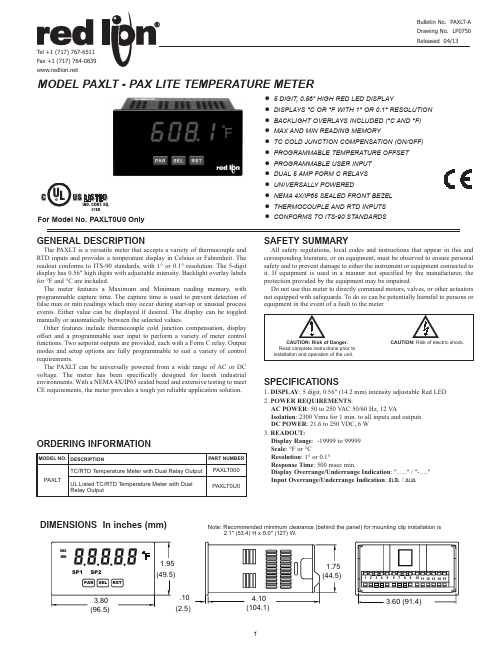
● 5 DIGIT, 0.56" HIGH RED LED DISPLAY● DISPLAYS °C OR °F WITH 1° OR 0.1° RESOLUTION ● BACKLIGHT OVERLAYS INCLUDED (°C AND °F)● MAX AND MIN READING MEMORY● TC COLD JUNCTION COMPENSATION (ON/OFF)● PROGRAMMABLE TEMPERATURE OFFSET ● PROGRAMMABLE USER INPUT ● DUAL 5 AMP FORM C RELAYS ● UNIVERSALLY POWERED● NEMA 4X/IP65 SEALED FRONT BEZEL ● THERMOCOUPLE AND RTD INPUTS ● CONFORMS TO ITS-90 STANDARDSMODEL PAXLT - PAX LITE TEMPERATURE METERDIMENSIONS In inches (mm)Note: Recommended minimum clearance (behind the panel) for mounting clip installation is 2.1" (53.4) H x 5.0" (127) W.WIRING OVERVIEWElectrical connections are made via screw-clamp terminals located on the back of the meter. All conductors should conform to the meter’s voltage and current ratings. All cabling should conform to appropriate standards of good installation, local codes and regulations. It is recommended that the power supplied to the meter (DC or AC) be protected by a fuse or circuit breaker. When wiring the meter, compare the numbers embossed on the back of the meter case against those shown in wiring drawings for proper wire position. Strip the wire, leaving approximately 0.3" (7.5 mm) bare lead exposed (stranded wires should be tinned with solder.) Insert the lead under the correct screw-clamp terminal and tighten until the wire is secure. (Pull wire to verify tightness.)EMC INSTALLATION GUIDELINESAlthough Red Lion Controls Products are designed with a high degree of immunity to Electromagnetic Interference (EMI), proper installation and wiring methods must be followed to ensure compatibility in each application. The type of the electrical noise, source or coupling method into a unit may be different for various installations. Cable length, routing, and shield termination are very important and can mean the difference between a successful or troublesome installation. Listed are some EMI guidelines for a successful installation in an industrial environment.1. A unit should be mounted in a metal enclosure, which is properly connected to protective earth.2. Use shielded cables for all Signal and Control inputs. The shield connection should be made as short as possible. The connection point for the shield depends somewhat upon the application. Listed below are the recommended methods of connecting the shield, in order of their effectiveness.3.3 USER INPUT WIRINGTerminal 8: User Input Terminal 9: User Common3.2 INPUT SIGNAL WIRING3.1 POWER WIRINGPowerTerminal 1: V AC/DC +Terminal 2: V AC/DC -a. Connect the shield to earth ground (protective earth) at one end where the unit is mounted.b. Connect the shield to earth ground at both ends of the cable, usually when the noise source frequency is over 1 MHz.3. Never run Signal or Control cables in the same conduit or raceway with AC power lines, conductors, feeding motors, solenoids, SCR controls, and heaters, etc. The cables should be run through metal conduit that is properly grounded. This is especially useful in applications where cable runs are long and portable two-way radios are used in close proximity or if the installation is near a commercial radio transmitter. Also, Signal or Control cables within an enclosure should be routed as far away as possible from contactors, control relays, transformers, and other noisy components.4. Long cable runs are more susceptible to EMI pickup than short cable runs.5. In extremely high EMI environments, the use of external EMI suppression devices such as Ferrite Suppression Cores for signal and control cables is effective. The following EMI suppression devices (or equivalent) are recommended:Fair-Rite part number 0443167251 (RLC part number FCOR0000)Line Filters for input power cables:Schaffner # FN2010-1/07 (Red Lion Controls # LFIL0000)6. To protect relay contacts that control inductive loads and to minimize radiated and conducted noise (EMI), some type of contact protection network isnormally installed across the load, the contacts or both. The most effective location is across the load.a. Using a snubber, which is a resistor-capacitor (RC) network or metal oxide varistor (MOV) across an AC inductive load is very effective at reducing EMI and increasing relay contact life.b. If a DC inductive load (such as a DC relay coil) is controlled by a transistor switch, care must be taken not to exceed the breakdown voltage of the transistor when the load is switched. One of the most effective ways is to place a diode across the inductive load. Most RLC products with solid state outputs have internal zener diode protection. However external diode protection at the load is always a good design practice to limit EMI. Although the use of a snubber or varistor could be used.RLC part numbers: Snubber: SNUB0000 Varistor: ILS11500 or ILS230007. Care should be taken when connecting input and output devices to the instrument. When a separate input and output common is provided, they should not be mixed. Therefore a sensor common should NOT be connected to an output common. This would cause EMI on the sensitive input common, which could affect the instrument’s operation.Visit RLC’s web site at /Support/InstallationConsiderations.html for more information on EMI guidelines, Safety and CE issues as they relate to Red Lion Controls products.OPERATING MODE DISPLAY DESIGNATORS MAX - Maximum display capture value MIN - Minimum display capture value“SP1” - Indicates setpoint 1 output activated.“SP2” - Indicates setpoint 2 output activated.Pressing the SEL button toggles the meter through the selected displays. If display scroll is enabled, the display will toggle automatically every four seconds between the enabled display values.USER INPUT ACTIVE LEVELSelect whether the user input is configured as active low or active high.If the displayed temperature is difficult to read due to small process variations or noise, increased levels of filtering will help to stabilize the display.The filter will adapt to variations in the input signal. When the variation exceeds the input filter band value, the filter disengages. When the variation becomes less than the band value, the filter engages again. This allows for a stable readout, but permits the display to settle rapidly after a large process change. The value of the band is in display units, independent of the Display Decimal Point position. A band setting of ‘0’ keeps the filter permanently engaged at the filter level selected above.Select the thermocouple or RTD type used for the application. For RTDs, position the Input Range Jumper to match the RTD type (10Ω or 100Ω).Selecting displays a millivolt signal readout with 10 µV resolution.USER INPUT FUNCTIONSelect the value(s) to which the User Input Function is assigned. The User Input Assignment only applies if a selection of reset or display hold is selected in the User Input Function menu.Software filtering effectively combines a fraction of the current input reading with a fraction of the previous displayed reading to generate the new display.Filter values represent no filtering (0), up to heavy filtering (3). A value of 1 for the filter uses 1/4 of the new input and 3/4 of the previous display to generate the new display. A filter value of 2 uses 1/8 new and 7/8 previous. A filter value of 3 uses 1/16 new and 15/16 previous.MODEReset *Program Mode Lock-out No FunctionDESCRIPTIONDISPLAY Display Select *Advance once for each activation. Setpoint 1 and 2 Reset *Setpoint 2 Reset *Setpoint 1 Reset *Reset both setpoint 1 and 2 outputs.Reset setpoint 2 output.Reset setpoint 1 output.Display Intensity Level *Increase intensity one level for each activation.Display Hold Holds the assigned display, but all other meter functions continue as long as activated (maintained action).Reset the assigned value(s) to the current input value.See Programming Mode Access chart (Module 3).User Input disabled.* Indicates Edge Triggered function. All others are Level Active functions.MIN DISPLAY ENABLEMIN CAPTURE DELAY TIMEWhen the Input Display is below the present MIN value for the entered delaytime, the meter will capture that display value as the new MIN reading. A delay time helps to avoid false captures of sudden short spikes.to sec.MAX CAPTURE DELAY TIMEWhen the Input Display is above the present MAX value for the entered delay time, the meter will capture that display value as the new MAX reading. A delay time helps to avoid false captures of sudden short spikes.to sec.MAX DISPLAY ENABLESelect to perform any of the Factory Service Operations shown below.FACTORY SERVICE OPERATIONSRESTORE FACTORY DEFAULT SETTINGSVIEW MODEL AND VERSION DISPLAYThis parameter sets the display update time in seconds.This selection allows the RST button to reset the selected value(s).The selection allows the display to automatically scroll through theenabled displays. The scroll rate is every 4 seconds. This parameter only appearswhen the MAX or MIN displays are enabled.Enter the desired Display Intensity Level (1-5). The display will actively dimor brighten as levels are changed.THERMOCOUPLE Voltage Calibration1. Connect a precision DC voltage source with an accuracy of 0.01% or betterto the TC and COMM terminals. Set the voltage source to zero.2. With the display at , press the PAR key. Unit displays .3. Press SEL until the display reads to select thermocouple input.4. Press PAR. Display reads .5. With the voltage source set to zero, press PAR. Display reads for about6 seconds.6. When the display reads , set the voltage source output to 60.000 mV.Press PAR. Display reads for about 6 seconds.7. When display reads , press PAR twice to exit calibration and return tothe normal display mode. Proceed to Cold Junction Calibration.THERMOCOUPLE Cold Junction Calibration1. The ambient temperature must be between 20°C and 30°C.2. Connect a thermocouple (types T, E, J, K or N only) with an accuracy of 1°Cor better to the meter.3. Enter programming mode and verify the following settings in Module 1:= thermocouple type connected to the meter= ; = ; = ; =4. Place the thermocouple in close thermal contact to a reference thermometerprobe. (Use a reference thermometer with an accuracy of 0.25°C or better.)The two probes should be shielded from air movement and allowed sufficienttime to equalize in temperature. (A calibration bath of known temperaturecould be used in place of the thermometer.)5. Compare the unit display with the reference temperature indicator (orcalibration bath). If a difference of more than +/- 1.0°C exists, note thedifference (CJ Error) and continue with cold junction calibration.CJ Error = Reference Temperature - Unit Display6. Enter programming mode and proceed through Module 2 to the ServiceAccess Code. Select and press PAR. Unit displays . PressRST to select .7. Press PAR. Display reads followed by the current cold junction value.Calculate a new cold junction value as follows:New cold junction = Current cold junction + CJ Error (noted above)8. Press PAR and set the display to the new cold junction value. Press PAR toenter the new value. Display reads for 6 seconds and returns to .9. Press PAR twice to exit calibration and return to the normal display mode.Verify the input reading is correct. If not, repeat steps 5 through 9.Select the Setpoint Output to be programmed, starting with Setpoint 1. The “ ” in the following parameters reflects the chosen Setpoint number. After the selected setpoint is completely programmed, the display returns to . Repeat steps for Setpoint 2 if both Setpoints are being used. Select to exit the Setpoint programming module.SETPOINT SELECTSelect to enable Setpoint and access the setup parameters. If isselected, the unit returns to and Setpoint is disabled.High Acting, with balanced hysteresis Low Acting, with balanced hysteresis High Acting, with unbalanced hysteresis Low Acting, with unbalanced hysteresis= = = =Enter the desired setpoint value. The decimal point position for the setpoint and hysteresis values follow the selection set in Module 1.Enter desired hysteresis value. See Setpoint Output Figures for visual explanation of how setpoint output actions (balanced and unbalanced) are affected by the hysteresis. When the setpoint is a control output, usually balanced hysteresis is used. For alarm applications, usually unbalanced hysteresis is used. For unbalanced hysteresis modes, the hysteresis functions on the low side for high acting setpoints and functions on the high side for low acting setpoints.Note: Hysteresis eliminates output chatter at the switch point, while time delay can be used to prevent false triggering during process transient events.Enter the time value in seconds that the output is delayed from turning off after the trigger point is reached. A value of 0.0 allows the meter to update the output status per the response time listed in the Specifications.OUTPUT RESET ACTIONThis parameter enables the RST button or user input to reset the output when the display is reset.Note: For this parameter to operate, the RST button or User Input being used must be set to and the Input value must be displayed. If these conditions are not met, the output will not reset.OUTPUT RESET WITH DISPLAY RESETWhen , the output is disabled (after a power up) until the trigger point is crossed. Once the output is on, the output operates normally per the Setpoint Action and Output Reset Action.Enter the probe burn-out action. In the event of a temperature probe failure (TC open; RTD open or short), the output can be programmed to be on or off.= Latch with immediate reset action; This action latches the output on atthe trigger point per the Setpoint Action shown in Setpoint Output Figures. Latch means that the output can only be turned off by the front panel RST button or user input manual reset, or meter power cycle. When the user input or RST button is activated (momentary action), the corresponding “on” output is reset immediately and remains off until the trigger point is crossed again. (Previously latched alarms will be off if power up Display Value is lower than setpoint value.)= Latch with delay reset action; This action latches the output on at the trigger point per the Setpoint Action shown in Setpoint Output Figures. Latch means that the output can only be turned off by the front panel RST button or user input manual reset, or meter power cycle. When the user input or RST button is activated (momentary action), the meter delays the event until the corresponding “on” output crosses the trigger off point. (Previously latched outputs are off if power up Display Value is lower than setpoint value. During a power cycle, the meter erases a previous reset if it is not activated at power up.)11S e t p o i n t A c t i o nS e t p o i n t S e l e c tS e t p o i n t V a l u e O u t p u t R e s e t A c t i o nH y s t e r e s i s V a l u eO f f T i m e D e l a yO n T i m e D e l a yO u t p u t R e s e t W i t h D i s p l a y R e s e tS t a n d b y O p e r a t i o nS e t p o i n t E n a b l e P r o b e B u r n -o u t A c t i o npaXlt prograMMing QuicK overvieWP r e s s P A R k e y t o e n t e r P r o g r a m m i n g M o d e .Red Lion Controls Headquarters20 Willow Springs Circle York PA 17406Tel +1 (717) 767-6511 Fax +1 (717) 764-0839Red Lion ControlsChinaUnit 302, XinAn PlazaBuilding 13, No.99 Tianzhou RoadShangHai, P.R. China 200223Tel +86 21 6113 3688Fax +86 21 6113 3683 Red Lion ControlsEuropeSoftwareweg 9NL - 3821 BN AmersfoortTel +31 (0) 334 723 225Fax +31 (0) 334 893 793Red Lion ControlsIndia201-B, 2nd Floor, Park CentraOpp 32 Mile Stone, Sector-30Gurgaon-122002 Haryana, IndiaTel +91 984 487 0503。
- 1、下载文档前请自行甄别文档内容的完整性,平台不提供额外的编辑、内容补充、找答案等附加服务。
- 2、"仅部分预览"的文档,不可在线预览部分如存在完整性等问题,可反馈申请退款(可完整预览的文档不适用该条件!)。
- 3、如文档侵犯您的权益,请联系客服反馈,我们会尽快为您处理(人工客服工作时间:9:00-18:30)。
说明书
一、性能参数
1.测量范围
温度测量范围:-55℃~125℃
2.测量精度
温度测量精度:±0.5℃
3.分辨率
温度分辨率:0.0625℃
4.外形尺寸
190×135×35(mm)
5.供电电源
⑴.9V直流稳压电源,此时有一个电源开关可以控制电源的通断;
⑵.通过USB 数据线(A 口转MiniAB)连接到PC 机为基板供电。
二、产品特点
1.128×64OLED显示屏,可手动切换显示温度、日期、星期和时间
2.手动校时、调整日期
3.最高∕最低温度记忆功能
4.℃∕℉切换显示
5.24小时制时钟
6.每日闹钟功能
7.立式或卧式
8.可通过RS232串口传输当前温度和时间至PC机
三、操作方法
1.开机上电后显示“中国海洋大学”图标、“中国海洋大学09级自动化”、“多功能温度计”等文字,显示过后自动进入温度显示模式;
2.进入温度显示模式后,拨动SW1可显示自开机上电或复位后所记录的摄氏最高∕最低温度值;拨动SW2可显示相对应的华氏最高∕最低温度值;拨动SW3可启动串行传输功能,此时可通过RS232串口传输当前温度和时间至PC机;将拨码开关拨回原位即可返回温度显示界面;
3.按下KEY1可在温度显示模式和日期、星期和时间显示模式之间来回切换;
4.进入日期、星期和时间显示模式后,按下KEY2进入校时模式,此时可通过KEY1选择校准小时、分钟、秒;
每次校准时,按下KEY3则对应项+1,按下KEY4则对应项-1;
小时或分钟或秒校准后都需要按下KEY2,此时显示对应项校准完成;所有项目均校准完成后,按下KEY4推出校时模式,返回日期、星期和时间显示模式;
5.进入日期、星期和时间显示模式后,按下KEY3进入调整日期模式,此时可通过KEY1选择调整年、月、日;
每次调整时,按下KEY3则对应项+1,按下KEY4则对应项-1;
年或月或日调整后都需要按下KEY2,此时显示对应项校准完成;所有项目均校准完成后,按下KEY4推出日期调整模式,返回日期、星期和时间显示模式;
6.进入日期、星期和时间显示模式后,拨动SW1进入闹钟设定模式,此时可通过KEY1选择设定小时、分钟以及取消闹钟;
每次设定时,按下KEY3则对应项+1,按下KEY4则对应项-1;
小时或分钟设定或取消闹钟后都需要按下KEY2,此时显示对应项设定完成;所有项目均设定完成后,将SW1拨回原退位即可出闹钟设定模式,返回日期、星期和时间显示模式;
7.闹钟响起时,拨动SW2即可停止响铃。
