1722智能相机
无需充电线!这款智能相机仅靠太阳就能工作

无需充电线!这款智能相机仅靠太阳就能工作如今,随着科技的不断发展,人们对于智能相机的需求也越来越大。
对于很多人来说,使用智能相机的一个令人头疼的问题就是充电。
因为无论是专业的摄影师还是普通的用户,都会苦恼于相机用电不足的问题。
近期有一款让人惊喜的智能相机问世,不仅能够智能拍照,还可以在没有电源的情况下通过太阳能进行充电。
这就是一款无需充电线的智能相机,仅靠太阳就能工作。
这一消息引起了广泛的关注,让我们一起来了解一下这款令人惊艳的智能相机吧。
这款智能相机的产品设计结合了高科技和环保理念,采用了先进的太阳能充电技术。
它的外观设计简洁,线条流畅,整体极具现代感。
整个相机的表面都覆盖了高效的太阳能充电板,保证了在充足的阳光下可以迅速进行充电。
这款相机在耗能方面也做了很多优化,采用了低功耗的芯片和节能型的电池,有效延长了使用时间。
这些设计都体现了制造商对于环保和可持续发展的重视,给用户带来了全新的使用体验。
这款智能相机在拍摄功能方面也是非常强大的。
它配备了一颗高像素的镜头和高清的摄像头,可以拍摄出清晰细腻的图片和视频。
而且,这款相机还具备了智能识别功能,能够自动识别目标,快速对焦并进行智能调整,确保每一张照片都是完美的。
这款相机还支持多种拍摄模式和滤镜效果,用户可以根据自己的需求进行自由选择,满足不同场景下的拍摄需求。
这款智能相机在功能方面是非常出色的,无论是日常拍摄还是专业摄影,都能够得心应手。
这款智能相机还具备了丰富的连接功能。
它支持Wi-Fi、蓝牙等多种连接方式,可以轻松连接到手机、电脑等设备上,实现照片的传输和分享。
这款相机还内置了智能芯片,支持人脸识别、语音识别等功能,用户可以通过简单的操作就能完成各种拍摄需求。
而且,这款相机还支持远程控制,用户可以通过手机APP实现对相机的遥控,无需过多操作就能够轻松完成拍摄任务。
这些连接功能的加入,使得这款相机的使用更加便捷,满足了用户日常拍摄的各种需求。
最重要的是,这款智能相机采用了全新的太阳能充电技术,摆脱了传统相机需要频繁充电的麻烦。
尼康 COOLPIX L22 L21 数码相机 说明书

松下 数码相机 DC-G100 使用说明书

池或重新连接交流电源适配器,再将本机打开。
请勿在无线电发射器或高压线附近使用本机。 • 如果您在无线电发射器或高压线附近拍摄,拍摄的图像和/
或声音可能会受到不良影响。
DVQX2059 (SCH)
7
安全注意事项
• 要清洁您的相机,请卸下电池或卡,或从插座拔下电源插 头,然后用软干布擦拭。
保持本机远离电磁设备(例如微波炉、电视机、游戏机等)。 • 如果您在电视机上面或附近使用本机,本机上的图像和/或
声音可能被电磁波辐射干扰。 • 请勿在移动电话附近使用本机,否则噪声可能对图像和/或
声音产生不良影响。 • 扬声器或大型电机产生的强大磁场可能造成记录的数据损坏
或图像失真。 • 电磁波辐射可能对本机造成不良影响,干扰图像和/或声音。 • 如果本机受电磁设备的不良影响而不能正常工作,请关闭本
使用注意事项
• 除了随机附送的以外,请勿使用任何其他USB连接电缆。 • 除了随机附送的或正品Panasonic手柄(DMW-SHGR1 :另售)
以外,请勿使用任何其他手柄。 • 使用带有HDMI标志的“高速HDMImicro电缆”。
不符合HDMI标准的电缆不能工作。
“高速HDMImicro电缆”(D型-A型插头,最长2 m) • 请勿使用3 m或以上长度的立体声麦克风电线。
10 DVQX2059 (SCH)
目录6. 驱动/图像稳定器55选择驱动模式 ................................ 55 图像稳定器 .................................. 56
7. 亮度(曝光)/着色/图像效果
57
[测光模式].................................. 57 曝光补偿 .................................... 58 ISO感光度 ................................... 59 白平衡(WB)................................. 61
QHY 5-II系列CCD使用手册

像素尺寸
3.75μm×3.75μm
有效感光面积
4.83mm×3.63mm
读出方式
逐行扫描
快门
电子滚动快门
曝光时间
20μs-10min
彩色 / 黑白
彩色或黑白
像素合并及合并类型 不支持
读出像素速率
24-74.5 MHz
最大读出帧率
30 FPS@1280×960 75 FPS@800×600 200 FPS@320×240
机械接口
自身为 1.25 英寸目镜尺寸
后截距
9.4mm
标配件
机身、限位环、USB 线、导星线、红外截止镜片(彩
色版为标配,黑白版为选配)
选配件
CS 镜头接口、超级散热器、三脚架接环、延长筒
05
QHY 5T-II
CMOS 芯片 CMOS 尺寸
Aptina MT9T001 1/2 英寸(4 :3 )
有效像素数
2048×1536
像素尺寸
3.2μm×3.2μm
有效感光面积
6.55mm×4.92mm
读出方式
逐行扫描
快门
电子滚动快门
曝光时间
20μs-10min
彩色 / 黑白
彩色
像素合并及合并类型 支持,2×2、3×3
读出像素速率
48/24/12 MHz
最大读出帧率
12 FPS@2048×1536 27 FPS@1280×1024 93 FPS@640×480 18 FPS@1920×1080 34 FPS@1024×768 2×2 BIN 48 FPS@640×480 3×3 BIN
尺寸
直径 31.6mm;长 52mm
重量
45g(不含限位环)
立林--智慧社区产品

申请时间
项类型
2017/9/30 梯口机-单网卡
2017/12/20 梯口机-单网卡
2017/5/17 梯口机-单网卡
2017/12/13 梯口机-单网卡
2017/8/9 梯口机-单网卡
2017/10/19 梯口机-单网卡
2017/6/6 梯口机-单网卡
2017/10/19 梯口机-单网卡
2017/11/30 梯口机-单网卡
民警:系统即时人口、房屋信息采集,数据共享,减轻社区民警工作量;特殊人员监 控,信息推送提醒。
社区: 网格化管理,辖区内人口、房屋信息及分布情况即时掌控,提升社区综合安防管 理水平。
物业:减轻物业人员工作量与危险发生的反查工作,自动筛选,和自定义的设置, 可以减少值勤人数,提高安全性的同时提升工作效率。
2017/5/17 梯口机-单网卡
2017/7/17 梯口机-单网卡
2017/5/17 梯口机-单网卡
2017/5/17 梯口机-单网卡
2017/8/15 梯口机-单网卡
2017/9/7 梯口机-单网卡
2017/8/29 梯口机-单网卡
2017/11/22 梯口机-单网卡
2017/12/21 梯口机-单网卡
外观
基本特性
软件
刷卡
触摸按键,4.3寸液 铝面 晶屏 板 触摸屏,7寸液晶屏
普通 二代证
指纹
触摸按键,4.3寸液 铝面 晶屏 板 触摸屏,7寸液晶屏
机械按键,10.1寸液
晶屏
铝本 色
机械按键,10.1寸液 晶屏
触摸按键,4.3寸液
晶屏,
双网卡
金色 铝面 板
触摸按键,4.3寸液 晶屏
铝压 铸
云对讲,IC
发现了么?今年旗舰手机的摄像头配置变了
发现了么?今年旗舰手机的摄像头配置变了作者:来源:《电脑报》2021年第35期即将到来的九十月,是每年手机新品上市的热门周期。
尤其是在iPhone秋季新品发布会前后的时间内,是各大品牌推陈出新的重要时段。
由于今年手机市场内外部形势的变化,品牌之间的竞争也相比之前更加白热化。
各家为了应对市场和消费需求的改变,在产品策略层面做出了更加灵活多样的调整和改进。
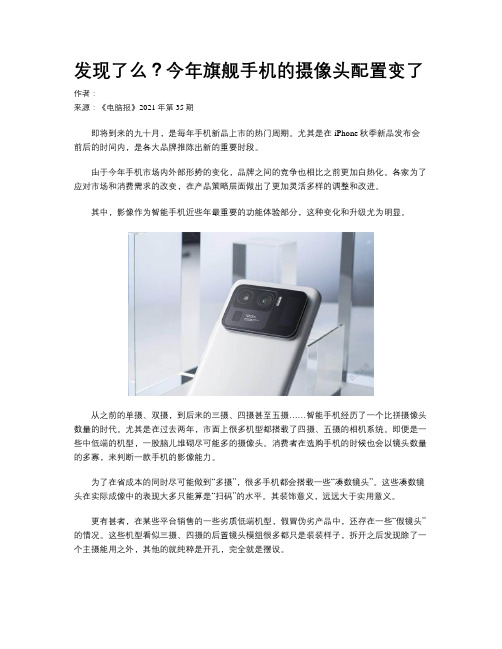
其中,影像作为智能手机近些年最重要的功能体验部分,这种变化和升级尤为明显。
从之前的单摄、双摄,到后来的三摄、四摄甚至五摄……智能手机经历了一个比拼摄像头数量的时代。
尤其是在过去两年,市面上很多机型都搭载了四摄、五摄的相机系统。
即便是一些中低端的机型,一股脑儿堆砌尽可能多的摄像头。
消费者在选购手机的时候也会以镜头数量的多寡,来判断一款手机的影像能力。
为了在省成本的同时尽可能做到“多摄”,很多手机都会搭载一些“凑数镜头”。
这些凑数镜头在实际成像中的表现大多只能算是“扫码”的水平。
其装饰意义,远远大于实用意义。
更有甚者,在某些平台销售的一些劣质低端机型,假冒伪劣产品中,还存在一些“假镜头”的情况。
这些机型看似三摄、四摄的后置镜头模组很多都只是装装样子,拆开之后发现除了一个主摄能用之外,其他的就纯粹是开孔,完全就是摆设。
这种情况在今年有所好转。
至少在主流品牌的旗舰产品上,凑数镜头变得越来越少。
这其实是手机影像在当前阶段的一次技术和体验上的“拨乱反正”。
正如之前我们预测的一样,手机镜头如今越来越没有“主副之分”。
除了常规的主摄成像能力之外,消费者也更加看重超长焦、超广角、人像、视频这些功能型镜头的成像能力。
与其为了追求数量,堆砌更多的凑数镜头,不如用心打磨好两三颗镜头相机的画质,让用户获得实实在在体验上的收益。
在这种产品思路转变之后,今年旗舰手机的超广角、人像等传统意义上的副摄的成像能力有了大幅度的升级。
小米、华为、OPPO等厂商甚至在这些镜头上采用了主摄规格的CMOS配置。
美的小子弹相机硬件说明书 A310、A311 2020 01 02

Mini Bullet Camera Hardware ManualA310, A3112020/01/02Table of ContentsPrecautions 3 Safety Instructions (5)Introduction 6List of Models (6)Package Contents (7)Physical Description (8)Installation Procedures 9Step 1: Install the Camera (9)Step 2: Waterproof and Connect the Cable(s) (11)Using the Cable Gland (11)Using an Optional Power Adapter (13)Step 3: Connect to Network (14)Step 4: Access the Camera Live View (14)Other Accessories 15 How to Install / Remove the Memory Card (15)Accessing the Camera 16Configure the IP Addresses (16)Using DHCP Server to Assign IP Addresses (16)Using the Default Camera IP Address (18)Access the Camera (22)PrecautionsRead these instructionsRead all the safety and operating instructions before using this product.Heed all warningsAdhere to all the warnings on the product and in the instruction manual. Failure to follow the safety instructions given may directly endanger people, cause damage to the system or to other equipment.ServicingDo not attempt to service this product yourself as opening or removing covers may expose you to dangerous voltage or other hazards. Refer all servicing to qualified service personnel.TrademarksACTi and ACTi logo are registered trademarks of ACTi Corporation. All other names and products used in this manual are registered trademarks of their respective companies.LiabilityEvery reasonable care has been taken during the writing of this manual. Please inform your local office if you find any inaccuracies or omissions. ACTi will not be held responsible for any typographical or technical errors and reserves the right to make changes to the product and manuals without prior notice.Federal Communications Commission StatementThis equipment has been tested and found to comply with the limits for aclass B digital device, pursuant to Part 15 of the FCC Rules. These limits aredesigned to provide reasonable protection against harmful interference in a residential installation. This equipment generates, uses, and can radiate radio frequency energy and, if not installed and used in accordance with the instructions, may cause harmful interference to radio communications. However, there is no guarantee that interference will not occur in a particular installation. If this equipment does cause harmful interference to radio or television reception, which can be determined by turning the equipment off and on, the user is encouraged to try to correct the interference by one or more of the following measures: ∙Reorient or relocate the receiving antenna.∙Increase the separation between the equipment and receiver.∙Connect the equipment into an outlet on a circuit different from that to which the receiver is connected.∙Consult the dealer or an experienced radio/TV technician for help.Warning: Changes or modifications to the equipment that are not expressly approved by the responsible party for compliance could void the user’s authority to operate the equipment.European Community Compliance StatementThis product has been tested and found to comply with the limits for Class BInformation Technology Equipment according to European Standard EN 55022 and EN 55024. In a domestic environment, this product may cause radio interference in which cause the user may be required to take adequate measures.Safety InstructionsCleaningDisconnect this product from the power supply before cleaning.Accessories and Repair PartsUse only the accessories and repair parts recommended by the manufacturer. Using other attachments not recommended by the manufacturer may cause hazards.Water and MoistureInstall other devices (such as PoE injector, alarm, etc.) that will be used with the camera in a dry place protected from weather.ServicingDo not attempt to service this product yourself. Refer all servicing to qualified service personnel.Damage Requiring serviceDisconnect this product from the power supply immediately and refer servicing to qualified service personnel under the following conditions.1) When the power-supply cord or plug is damaged2) If liquid has been spilled, or objects have fallen into the product.3) If the inner parts of product have been directly exposed to rain or water.4) If the product does not operate normally even by following the operating instructions in thismanual. Adjust only those controls that are covered by the instruction manual, as improper adjustment of other controls may result in damage, and will often require extensive work by a qualified technician to restore the product to its normal operation.Safety CheckUpon completion of any service or repairs to this product, ask the service technician to perform safety checks to determine if the product is in proper operating condition.IntroductionList of ModelsThis hardware manual contains the following models:4MP Mini Bullet with D/N, Adaptive IR, Extreme WDR, SLLS,Fixed lens6MP Mini Bullet with D/N, Adaptive IR, Superior WDR, SLLS,Fixed lensPackage ContentsPhysical DescriptionInstallation ProceduresStep 1: Install the Camera1. Mark the screw holes or attach the bundled drill template on the target surface.NOTE: Depending on the surface where you will install the camera, it may be necessary to drill three (3) holes and use the supplied screw tox.2. If the cable will pass through the surface, drill the cable hole within the radius of thecamera bracket. If the cable will be routed along the surface, route the cable through the gap on the bracket.3. Mount the camera to the surface using the three (3) screws.4. Loosen the knob to adjust the camera tilt and orientation. The camera can be panned bytwisting the bracket stem.5. Adjust the camera angle and orientation.Sample of Wall Installation6. Tighten the knob and the set screw to fix the tilt angle position.orStep 2: Waterproof and Connect the Cable(s)If the camera will be installed indoors, simply connect the network side cable to the camera Ethernet port.However, if the camera will be installed outdoors, ensure that the cable connections and the network side cable itself are also protected from water and other environmental factors. Use the bundled cable gland for the Ethernet connector and use waterproof tape to protect the other cable connection.Using the Cable GlandThis section describes how to waterproof the cable-out or “pigtail” of the camera using the bundled cable gland. Before connection, prepare an exterior-grade Ethernet cable with RJ-45 connector.Perform the following to waterproof the “pigtail” using the cable gland: 1. Attach the washer to the Ethernet connector of the camera.2. Detach the clamping nut and sealing insert from the gland body:Gland BodyClamping NutSealing Insert3.Insert the clamping nut into the Ethernet cable.4.Insert the sealing insert through the Ethernet cable.5.Insert the cable through the gland body.6.Push the sealing insert into the gland body.7.Connect the RJ-45 connector to the camera connector.8.Attach the gland body to the camera connector.9.Attach the clamping nut to the gland body to complete the cable solution.NOTE: Make sure the clamping nut is tightly attached to the cable gland body and the sealing insert is squeezed tightly.Using an Optional Power AdapterThe camera can be powered by a Power over Ethernet (PoE) switch that is IEEE802.3af compliant. In case of using a non-PoE switch or your PoE switch has a limited power supply, you can purchase a power adapter and directly connect the camera to a power outlet. NOTE: The power adapter is not bundled in the package.After connecting the power adapter, waterproof the cable connection by using waterproof tape.Step 3: Connect to NetworkConnect the other end of the network cable to a PoE switch or injector. Then, connect the switch or injector to a network, PC, and a power source. See Power-over-Ethernet (PoE) connection example below.PoE Injector / Switch Power CableEthernet CableCameraStep 4: Access the Camera Live ViewAfter making the connections, access the camera live view to adjust the viewing angle of the camera and configure the settings according to your preference. See Accessing the Camera on page 16 for more information.Other AccessoriesHow to Install / Remove the Memory Carding the bundled wrench, loosen the two (2) screws to remove the cover.2.Push the microSD card into the memory card slot with the metal contacts facing thelens.3.Secure the two (2) screws to attach the cover. Make sure the rubber on the cover is inplace.Accessing the CameraConfigure the IP AddressesIn order to be able to communicate with the camera from your PC, both the camera and the PC have to be within the same network segment. In most cases, it means that they both should have very similar IP addresses, where only the last number of the IP address is different from each other. There are 2 different approaches to IP Address management in Local Area Networks – by DHCP Server or Manually.Using DHCP Server to Assign IP AddressesIf you have connected the computer and the camera into the network that has a DHCP server running, then you do not need to configure the IP addresses at all – both the camera and the PC would request a unique IP address from DHCP server automatically. In such case, the camera will immediately be ready for the access from the PC. The user, however, might not know the IP address of the camera yet. It is necessary to know the IP address of the camera in other to be able to access it by using a Web browser.The quickest way to discover the cameras in the network is to use the simplest network search, built in the Windows system –just by pressing the “Network” icon, all the cameras of the local area network will be discovered by Windows thanks to the UPnP function support of our cameras.In the example below, we successfully found the camera model that we had just connected to the network.By double-clicking with the left mouse on the camera model, it is possible to automatically launch the default browser of the PC with the IP address of the target camera filled in the address bar of the browser already.If you work with our cameras regularly, then there is even a better way to discover the cameras in the network– by using IP Utility. The IP Utility is a light software tool that can not only discover the cameras, but also list lots of valuable information, such as IP and MAC addresses, serial numbers, firmware versions, etc, and allows quick configuration of multiple devices at the same time.The IP Utility can be downloaded for free from /IP_UtilityWith just one click, you can launch the IP Utility and there will be an instant report as follows:You can quickly see the camera model in the list. Click on the IP address to automatically launch the default browser of the PC with the IP address of the target camera filled in the address bar of the browser already.Using the Default Camera IP AddressIf there is no DHCP server in the given network, the user may have to assign the IP addresses to both PC and camera manually to make sure they are in the same network segment.When the camera is plugged into network and it does not detect any DHCP services, it will automatically assign itself a default IP:192.168.0.100Whereas the default port number would be 80. In order to access that camera, the IP address of the PC has to be configured to match the network segment of the camera.Manually adjust the IP address of the PC:In the following example, based on Windows 7, we will configure the IP address to192.168.0.99 and set Subnet Mask to 255.255.255.0 by using the steps below:1 23 4Manually adjust the IP addresses of multiple cameras:If there are more than 1 camera to be used in the same local area network and there is no DHCP server to assign unique IP addresses to each of them, all of the cameras would then have the initial IP address of 192.168.0.100, which is not a proper situation for network devices – all the IP addresses have to be different from each other. The easiest way to assign cameras the IP addresses is by using IP Utility:With the procedure shown above, all the cameras will have unique IP addresses, starting from 192.168.0.101. In case there are 20 cameras selected, the last one of the cameras would have the IP 192.168.0.120.Later, by pressing the “Refresh” button of the IP Utility, you will be able to see the list of cameras with their new IP addresses.Please note that it is also possible to change the IP addresses manually by using the Web browser. In such case, please plug in only one camera at a time, and change its IP address by using the Web browser before plugging in the next one. This way, the Web browser will not be confused about two devices having the same IP address at the same time.Access the CameraNow that the camera and the PC are both having their unique IP addresses and are under the same network segment, it is possible to use the Web browser of the PC to access the camera.You can use Microsoft Internet Explorer to access the camera.When using Internet Explorer browser, the ActiveX control for video stream management will be downloaded from the camera directly – the user just has to accept the use of such control when prompted so. No other third party utilities are required to be installed in such case.Hardware Manual21The following examples in this manual are based on Internet Explorer browser in order to cover all functions of the camera.Assuming that the camera’s IP address is 192.168.0.100, you can access it by opening the Web browser and typing the following address into Web browser’s address bar:http://192.168.0.100Upon successful connection to the camera, the user interface called Web Configurator would appear together with the login page. The HTTP port number was not added behind the IP address since the default HTTP port of the camera is 80, which can be omitted from the address for convenience.When you login, you will be asked to set a password. Follow the on-screen instructions to continue.Copyright © 2019, ACTi Corporation All Rights Reserved7F, No. 1, Alley 20, Lane 407, Sec. 2, Ti-Ding Blvd., Neihu District, Taipei, Taiwan 114, R.O.C.TEL : +886-2-2656-2588 FAX : +886-2-2656-2599Email:**************。
双星dsu02参数

双星dsu02参数全文共四篇示例,供读者参考第一篇示例:双星dsu02参数是一款新一代的数码相机,具有高画质、多功能、易操作等特点。
该相机采用了先进的技术,配备了多种功能,可以满足各种不同场景的拍摄需求。
下面我们来详细介绍一下双星dsu02参数及其特点。
首先是双星dsu02参数的画质。
这款相机采用了高性能的CMOS 传感器,有效像素达到了2000万像素,能够拍摄出清晰、细致的照片。
无论是拍摄风景、人物还是静物,都能够呈现出真实的色彩和细节,让您的照片更加生动、立体。
双星dsu02参数的功能也非常丰富多样。
除了基本的拍照功能外,还具有多种拍摄模式,如全景拍摄、夜景拍摄、微距拍摄等,可以满足不同场景下的拍摄需求。
该相机还支持高清视频录制功能,让您记录下生活中的每一个珍贵时刻。
双星dsu02参数的操作也非常简便。
相机配备了大尺寸的液晶显示屏,操作界面清晰、直观,方便用户进行各种设置和调整。
相机还配备了一键拍照功能,只需按下按钮,即可快速拍摄,让您不会错过任何精彩瞬间。
双星dsu02参数还具有良好的外观设计和做工。
相机采用了金属材质,手感顺滑,质感十足,同时还具有防水、防尘、防摔等功能,保护相机不受外界环境的影响。
双星dsu02参数是一款性能优越、功能丰富、操作简便、外观精美的数码相机,适合各种拍摄爱好者使用。
如果您对拍摄有着热情,不妨考虑购买一台双星dsu02参数的数码相机,让您记录下更多美好的瞬间。
第二篇示例:【双星dsu02参数】是一种常见的数字信号处理器,用于处理数字信号在通信系统中的传输和接收。
双星dsu02参数的设计目的是为了提供高性能的处理能力和灵活的配置选项,以满足不同通信系统的需求。
本文将深入探讨双星dsu02参数的技术特点和应用场景。
双星dsu02参数采用了先进的数字信号处理技术,可以实现高速数据处理和精确的信号解调。
它具有多核处理器架构,采用了高性能的数字信号处理算法,可以实现对复杂数字信号的实时处理和分析。
- 1、下载文档前请自行甄别文档内容的完整性,平台不提供额外的编辑、内容补充、找答案等附加服务。
- 2、"仅部分预览"的文档,不可在线预览部分如存在完整性等问题,可反馈申请退款(可完整预览的文档不适用该条件!)。
- 3、如文档侵犯您的权益,请联系客服反馈,我们会尽快为您处理(人工客服工作时间:9:00-18:30)。
Smart Cameras for Embedded Machine Vision OverviewNI 17xx Smart Cameras simplify machine vision by analyzing images directly on the camera with a powerful, embedded processor capable of running the entire suite of NI vision algorithms. You can use these cameras in a variety of applications including part location, defect detection, code reading, and assembly verification. The combination of the onboard processor with a charge-coupled device (CCD) image sensor provides an easily distributed, all-in-one vision system that transmits inspection results along with or in place of raw images. Housed in a rugged metal case designed for use in industrial applications, all NI Smart Cameras offer built-in I/O, multiple industrial protocols, built-in Web servers, and many other features. You can configure NI Smart Cameras with the included NI Vision Builder for Automated Inspection (AI) software or program the camera with LabVIEW Real-Time.Flexible Industrial I/OTo communicate results to other industrial devices, NI Smart Cameras offer built-in digital I/O and support both Ethernet- and serial-based industrial protocols such as Modbus TCP. NI Smart Camera digital I/O lines are optoisolated for direct connectivity with industrial devices such as triggers and actuators. All NI Smart Cameras offer two optoisolated digital inputs and two optoisolated digital outputs.To simplify Ethernet-based communication, NI Smart Cameras include two gigabit Ethernet ports. With one port connected to an industrial network to report inspection results, the other port can directly communicate with programmable automation controllers (PACs) such as NI CompactRIO or Compact FieldPoint, with industrial devices such as programmable logic controllers (PLCs), or with human machine interfaces (HMIs). All NI Smart Cameras include an RS232 serial port and 5 and 24 V lighting strobe outputs that you can use for synchronization with third-party lighting controllers.NI Smart Cameras, with the exception of the NI 1722, include quadrature encoder support for synchronizing inspections with linear and rotary drive systems. This feature simplifies timing in complex applications where consistency is critical to system success.Direct Drive LightingTo directly illuminate objects underthe camera, NI Smart Camerasfeature direct drive lighting. Lightingcontrollers can be costly additionsto machine vision applications.NI Smart Cameras have a built-inlighting controller so you can directlydrive lights from the camera itself, lowering costs and simplifying wiring. The built-in direct drive lighting controller can provide a constant DC current of 500 mA or a strobed current of up to 1 A. With strobed lighting, you can increase the intensity produced by up to four times without harming the light head. Most current-driven LED light heads work with the NI Smart Camera’s direct-drivefeature (this feature is not included on the NI 1722).•Real-time machine vision•High-quality monochrome VGA (640x480) or SXGA (1280x1024) CCD image sensors •High-performance embedded processors •Isolated 24 V digital I/O•Dual gigabit Ethernet ports•RS232 serial support•Support for industrial protocols •Expansion analog and digital I/O through NI Compact FieldPoint and CompactRIO •Built-in NI direct drive lighting controller for current-controlled LED light heads1•Quadrature encoder support11Not supported by NI 1722 Smart Camera Recommended Software •Vision Builder for Automated Inspection (included) or•LabVIEW and the LabVIEW Real-Time Vision Development Bundle Recommended Accessories•C-mount lens•Power and I/O cables•Mounting bracketNI 17xx Smart CamerasNEW!Camera ComparisonsNational Instruments offers a variety of smart cameras to meet a breadth of machine vision application needs.All NI Smart Cameras process images using onboard PowerPC processors. In higher-performance models, a Texas Instruments digital signal processor (TI DSP) acts as a coprocessor to boost the performance of specific algorithms. The image sensors inside all NI Smart Cameras are charge-coupled devices (CCDs).NI 1722 Smart Camera– Powered by a 400 MHz PowerPC processor; features a VGA (640x480) resolution CCD image sensor that can acquire images up to 60 fps.NI 1742 Smart Camera – Powered by a 533 MHz PowerPC processor; acquires VGA resolution (640x480) monochrome images at up to 60 fps.NI 1744 Smart Camera– Uses the same 533 MHz processor as the NI 1742 but features a higher-resolution CCD that acquires images of 1.3 megapixels (1280x1024); with higher resolution, you can inspect objects for smaller defects and make measurements with four times the resolution of previous NI Smart Cameras.NI 1762 Smart Camera– Offers a 720 MHz TI DSP coprocessor alongside the 533 MHz PowerPC, making it possible to run specific algorithms up to four times faster with no changes to the application software (works well for engineers needing higher performance for pattern matching, optical character recognition, and datamatrix code reading); contains the same VGA resolution (640x480) image sensor found in the previous NI Smart Cameras.NI 1764 Smart Camera – Provides the 1.3 megapixel image sensor found in the NI 1744, and the 720 MHz TI DSP coprocessor found in the NI 1762; ideal for high-speed manufacturing.SoftwareUnmatched ScalabilityAll NI Smart Cameras include the NI Vision Builder for Automated Inspection (AI) configurable vision application development environment so you can build and deploy complete machine vision applications quickly and easily. Vision Builder AI applications are based on an easy-to-use state diagram model. With this model, you can configure sophisticated inspections that include loops and branches without programming. Vision Builder AI also features all of the steps you need to develop complete machine vision systems, including advanced triggering, acquisition from data acquisition devices, communication with HMIs and PLCs, and control of digital I/O lines.For more advanced applications, NI Smart Cameras are also full-featured NI LabVIEW Real-Time targets. This adds the power of LabVIEW and the world-class algorithms in the NI Vision Development Module to this new platform. Other modules supported in LabVIEW Real-Time, such as the LabVIEW Control Design and Simulation Module, also work with NI Smart Cameras.NI vision software makes it easy to move between a configurable environment and a programming environment. With Vision Builder AI, you can create an inspection and easily convert it to LabVIEW code. If you want to use Vision Builder AI but need a bit more flexibility than it offers, you can also create custom steps for Vision Builder AI using LabVIEW.Hardware ScalabilityThe NI vision hardware platform ranges from PCI- and PXI-based systems to compact vision systems to the sensor itself with NI Smart Cameras. This entire range of hardware works with both LabVIEW and Vision Builder AI. This means you can design and prototype your machine vision algorithms using an off-the-shelf machine vision camera connected to an NI frame grabber and deploy that same application to an NI Smart Camera with minimal changes to your LabVIEW code or Vision Builder AI inspection.Software – Configure or ProgramVision Builder forAutomated InspectionVision Builder (AI) is a configurablemachine vision development environmentthat requires no programming. With theVision Builder AI, you can:•Build, benchmark, and deploy complete machine vision applications without programming•Configure more than 40 powerful machine vision tools including pattern matching, OCR, and particle analysis•Create custom user interfaces for display and control purposes •Host user interfaces on a built-in Web server•Communicate with industrial protocols over serial and EthernetLabVIEW Real-Time VisionDevelopment BundleThe NI LabVIEW Real-Time VisionDevelopment Bundle includes all thesoftware you need to program areal-time machine vision application with LabVIEW. You must purchase LabVIEW separately.The bundle includes:•LabVIEW Real-Time Module•LabVIEW Application Builder•NI Vision Development ModuleThe Vision Development Module, a library of image processing and machine vision functions, includes the Vision Assistant, an interactive prototyping environment that generates ready-to-run code. The Vision Development Module delivers:•Hundreds of image processing functions including pattern and geometric matching, OCR, bar code readers, object classification, and particle analysis•Tools to enhance images, check for presence, locate features, identify objects, and gauge parts•Fast application prototyping and code generation with theVision Assistant•Subpixel accuracy down to 1/10 of a pixel and 1/10 of a degreeFigure 1. With the scalability of NI vision software, you can develop your code on a PC, prototype on an NI Compact Vision System, and deploy to an NI Smart Camera without ever changing your application development environment.National Instruments vision software includes hundreds of imageprocessing and analysis functions. A subset of the tools available in the Vision Development Module and Vision Builder AI are shown below.Image SegmentationNI vision software comes with several options tosegment and partition images into related components.Segmentation is an important part of many imagingapplications that need to extract certain features or objects in order to process them further.Pattern and Geometric MatchingLearn and locate objects and patterns in yourimages. The National Instruments patented matching algorithms locate patterns fast withvery high accuracy.Bar Code Reader and GraderRead 1D bar codes as well as 2D codes like Data Matrix and PDF 417. You can decipher codes applied through ink jets, thermal transfer, laser etching, or dot peen. Spatial CalibrationUsing spatial calibration functions, you cancalibrate your image to take accurate, real-world measurements from images, regardless of camera perspective or lens distortion. Image Arithmetic and Logic FunctionsOperators perform basic arithmetic and logical operations on images. Use operators to add,subtract, multiply, and divide an image with otherimages or constants.Coordinate SystemsSet up coordinate systems to ensure that all your measurements move with the object within the field of view.Image Filters and Frequency AnalysisFrequency filters, such as the fast Fouriertransform (FFT), alter pixel values with respect to the periodicity and spatial distribution of the variations in light intensity in the image. Golden Template ComparisonFind defects in an image by comparing a perfect(golden) sample to all subsequent samples. Goldentemplate comparison detects surface defects, label misprints, and overall quality issues.Optical Character Recognition/VerificationNI OCR functions use a trainable OCR algorithm specifically designed to identify and verify all types of fonts, characters, and symbols despite poor and inconsistent image quality. Particle AnalysisUse particle analysis to detect connected regions or groupings of pixels in an image and make selected measurements of those regions. Choose from more than 80 unique measurements that return data in both real-world and pixel values.Color InspectionColor matching quantifies which colors and how much of each color exist in a region of an image and uses this information to check if anotherimage contains the same colors in the same ratio. Edge DetectionUse the edge detection tools to identify and locate discontinuities in the pixel intensities of an image.Find edges to align, measure, or detect features in the image.Object ClassificationClassification is a tool for identifying an unknown object by comparing its significant features to a set of features that represent known samples.GaugingUse dimensional measurement or gauging tools to obtain quantifiable, critical distance measurements such as distances, angles, areas, line fits, circular fits, and counts.Smart Camera AccessoriesLightingAll NI Smart Cameras except for the NI 1722provide direct connectivity to many current-controlled LED light heads, including those below. Additional lighting is available from Advanced Illumination ().Back light (red)......................................................................780221-01Ring light (red)......................................................................780222-01Linear array (red)..................................................................780223-01Spot light (red)......................................................................780224-01LensesNI Smart Cameras work with any standard C-mount lens, including the lenses below supplied by Computar.8 mm, F1.4, megapixel, Computar........................................780024-0112 mm, F1.4, megapixel, Computar......................................780025-0116 mm, F1.4, megapixel, Computar......................................780026-0125 mm, F1.4, megapixel, Computar......................................780027-01Cables and Power SuppliesNI 17xx unshielded screw terminalbreakout with 2 m cable ..................................................780261-01NI Smart Camera I/O accessory............................................780443-01Desktop power supply, 24 V, 63 W ......................................780237-01DIN-rail mount power supply................................................778805-9015-pin high-density D-Sub male to flying leads, 5 m ..........197818-05Ethernet cables, twisted pair1 m ....................................................................................182219-015 m ....................................................................................182219-0510 m ..................................................................................182219-10Smart Camera Mounting1⁄4 in.-20 tripod adapter..........................................................780239-01Mounting bracket..................................................................780240-01Expansion I/O and HMIsIf your applications need more I/O than NI Smart Cameras provide, you can easily connect expansion I/O over standard Ethernet. Compact FieldPoint and CompactRIO are two popular NI platforms for expansion I/O. Both of these platforms are built on real-time architectures, ensuring the determinism needed for many industrial applications. CompactRIO also features a built-in field-programmable gate array (FPGA) for precise timing and synchronization. Communication to both of these platforms is simplified with the use of shared variables in LabVIEW or Vision Builder AI. For more information on these platforms, visit /compactfieldpoint or /compactrio .For interfacing options, NI offers a full suite of touch panel HMIs.With the LabVIEW Touch Panel Module, you can develop custom HMI applications for Windows CE touch panel devices. Other options include Windows XP HMI devices that can run the entire LabVIEW development environment. Or simply target NI Smart Cameras and other PAC devices through a Web browser with the Web server technology available on these hardware platforms. For more information on HMI options from NI, visit /hmi.Ordering InformationNI 1722 Smart Camera with Vision Builder AI ....................780146-01NI 1742 Smart Camera with Vision Builder AI ....................780147-01NI 1744 Smart Camera with Vision Builder AI ....................780403-01NI 1762 Smart Camera with Vision Builder AI ....................780306-01NI 1764 Smart Camera with Vision Builder AI....................780402-01Additional SoftwareNI LabVIEW ..........................................................................776670-09NI LabVIEW Real-Time Vision Development Bundle............779324-03BUY NOW!/vision .Specifications>>For complete specifications, see the NI 17xx Smart Camera User Manual at /manuals.Image SensorProcessor CharacteristicsProcessorNI 1722...........................................400 MHz Freescale PowerPC NI 1742/1744..................................533 MHz Freescale PowerPCNI 1762/1764..................................533 MHz Freescale PowerPC and720 MHz Texas Instruments DSP Memory...............................................128 MBNonvolatile program storage..............128 MBImage/data storage............................Unlimited through FTP orEthernet hard drive Lighting ConnectivityNI 17225 and 24 V external strobe.............Programmable durationNI 1742, 1744, 1762, 17645 and 24 V external strobe.............Programmable duration Direct drive lighting........................500 mA DC, 1 A strobedI/O ConnectivityDigital input........................................ 2 channels optoisolated 24 V Digital output...................................... 2 channels optoisolated 24 V Ethernet............................................... 2 ports (10/100/1000 Mb/s)RS232 serial........................................Up to 230.4 kb/s Quadrature encoder............................Phase A/Phase B, no index(not available on NI 1722) Power RequirementsMain supply voltage...........................24 VDC, +20%, -15% (IEC 1311) Max currentNI 1722...........................................450 mANI 1742, 1744, 1762, 1764.............800 mA (with direct drive lighting) Physical SpecificationsLens mount..........................................C-mount Dimensions..........................................11.765 by 8.58 by 5.06 cm Weight.................................................525 g Safety and ComplianceSafetyThis product is designed to meet the requirements of the following standards of safety for electrical equipment for measurement, control, and laboratory use:•IEC 61010-1, EN 61010-1•UL 61010-1, CSA 61010-1Note:For UL and other safety certifications, refer to the product label or visit /certification, search by model number or product line, and click the appropriate link in the Certification column. Electromagnetic CompatibilityThis product meets the requirements of the following EMC standards for electrical equipment for measurement, control, and laboratory use:•EN 61326 (IEC 61326): Class A emissions; Basic immunity•EN 55011 (CISPR 11): Group 1, Class A emissions•AS/NZS CISPR 11: Group 1, Class A emissions•FCC 47 CFR Part 15B: Class A emissions•ICES-001: Class A emissionsNote:For EMC compliance, operate this product according to the documentation.CE ComplianceThis product meets the essential requirements of applicable European Directives, as amended for CE marking, as follows:•2006/95/EC; Low-Voltage Directive (safety)•2004/108/EC; Electromagnetic Compatibility Directive (EMC) Note:Refer to the Declaration of Conformity (DoC) for this product for any additional regulatory compliance information. To obtain the DoC for this product, visit /certification, search by model number or product line, and click the appropriate link in the Certification column. Waste Electrical and Electronic Equipment (WEEE)EU Customers:At the end of their life cycle, all products must be sent to a WEEE recycling center. For more information about WEEE recycling centers and National Instruments WEEE initiatives,visit /environment/weee.htm.Mechanical DrawingsFigure 2. Camera Front Figure 3. Camera BackFigure 4. Camera Side Figure 5. Camera BottomNI Services and SupportNI has the services and support to meet your needs around the globe and through the application life cycle – from planning and development through deployment and ongoing maintenance. We offer services and service levels to meet customer requirements in research,design, validation, and manufacturing. Visit /services .Training and CertificationNI training is the fastest, most certain route to productivity with our products. NI training can shorten your learning curve, save development time, and reduce maintenance costs over the application life cycle. We schedule instructor-led courses in cities worldwide, or we can hold a course at your facility. We also offer a professional certification program that identifies individuals who have high levels of skill and knowledge on using NI products. Visit /training .Professional ServicesOur NI Professional Services team is composed of NI applications and systems engineers and a worldwide National Instruments Alliance Partner program of more than 600 independent consultants andintegrators. Services range from start-up assistance to turnkey system integration. Visit /alliance .OEM SupportWe offer design-in consulting and product integration assistance if you want to use our products for OEM applications. For information about special pricing and services for OEM customers, visit /oem .Local Sales and Technical SupportIn offices worldwide, our staff is local to the country, giving you access to engineers who speak your language. NI delivers industry-leading technical support through online knowledge bases, our applications engineers, and access to 14,000 measurement and automationprofessionals within NI Developer Exchange forums. Find immediate answers to your questions at /support .We also offer service programs that provide automatic upgrades to your application development environment and higher levels of technical support. Visit /ssp .Hardware ServicesSystem Assurance ProgramsNI system assurance programs are designed to make it even easier for you to own an NI system. These programs include configuration and deployment services for your NI PXI, CompactRIO, or Compact FieldPoint system. The NI Basic System Assurance Program provides a simple integration test and ensures that your system is delivered completely assembled in one box.When you configure your system with the NI Standard System Assurance Program,you can select from available NI system driver sets and application development environments to create customized, reorderable software configurations.Your system arrives fully assembled and tested in one box with your software preinstalled. When you order your system with the standard program, you also receive system-specific documentation including a bill of materials, an integration test report, a recommended maintenance plan, and frequently asked question documents. Finally, the standard program reduces the total cost of owning an NI system by providing three years of warranty coverage and calibration service. Use the online product advisors at /advisor to find a system assurance program to meet your needs.Calibration ServicesNI recognizes the need to maintain properly calibrated devices for high-accuracy measurements. We provide manual calibration procedures, services to recalibrate your products, and automated calibration software specifically designed for use by metrology laboratories. Visit /calibration .Repair and Extended WarrantyNI provides complete repair services for our products. Express repair and advance replacement services are also available. We offerextended warranties to help you meet project life-cycle requirements. Visit /services.National Instruments • info@• 800 813 3693*351546C-01*351546C-012008-10395-221-101-D。