Baumer智能相机样本
民老特HI·Matic E 35mm自动焦距相机说明书
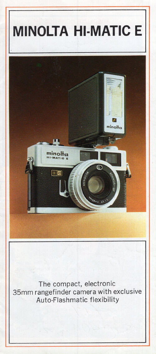
MINUTELY PRECISE, PROGRAMMED ELECTRONIC SHUTTER
For optimal photography both in daylight and in darkness, the Hi·matic E's shutter is programmed throughout the camera 's entire operating range.
ABSOLUTE CONTROL INFORMATION CENTER VIEWFINDER
The Hi ·matic E viewfinder gives you all the infor· mation you ' ll ever need f or perfect pictures. And it gives it to you at a glance.
AUTOMATIC PARALLAX CORRECTION The "bright frame" in the viewfinder shows ex· actly what will be in your finished slide or print. This frame automatically makes adjustments for the difference between what you see and what the lens is actually photographing.
SPECIAL FEATURES
FAST, SHARP ROKKOR LENS The Hi·matic E features the famous Rokkor Lens made exclusively by Minolta for Minolta cameras. This fast 40mm F1.? lens is color corrected to give clear, beautifully balanced color pictures.
Illustra Essentials 室内 室外高清迷你圆顶红外摄像机用户手册说明书

Illustra Essentials Indoor / Outdoor HD Mini Dome with IRUser Manual 8200-1102-04 C0NoticePlease read this manual thoroughly and save it for future use before attempting to connect or operate this unit.The information in this manual was current when published. The manufacturer reserves the right to revise and improve its products. All specifications are therefore subject to change without notice.CopyrightUnder copyright laws, the contents of this manual may not be copied, photocopied, reproduced, translated orreduced to any electronic medium or machine-readable form, in whole or in part, without prior written consent of Tyco Security Products. © 2015 Tyco Security Products. All rights reserved.Customer ServiceThank you for using Tyco Security Products. We support our products through an extensive worldwide network of dealers. The dealer through whom you originally purchased this product is your point of contact if you needservice or support. Our dealers are empowered to provide the very best in customer service and support.Dealers should contact Tyco Security Products at (800) 507-6268 or (561) 912-6259 or on the Web at.TrademarksThe trademarks, logos, and service marks displayed on this document are registered in the United States [orother countries]. Any misuse of the trademarks is strictly prohibited and Tyco Security Products. willaggressively enforce its intellectual property rights to the fullest extent of the law, including pursuit of criminalprosecution wherever necessary. All trademarks not owned by Tyco Security Products. are the property of their respective owners, and are used with permission or allowed under applicable laws.Product offerings and specifications are subject to change without notice. Actual products may vary fromphotos. Not all products include all features. Availability varies by region; contact your sales representative.Important Safeguards and Warnings 1.Electrical safetyAll installation and operation should conform to your local electrical safety codes.The power shall conform to the requirement in the SELV (Safety Extra Low Voltage) and the Limited power source is rated 12V DC or 24V AC in the IEC60950-1. (Refer to general introduction)Please note: Do not connect two power supplying sources to the device at the same time; it may result in device damage! The product must be grounded to reduce the risk of electronic shock.We assume no liability or responsibility for all the fires or electrical shock caused by improper handling or installation.We are not liable for any problems caused by unauthorized modification or attempted repair. 2.Transportation securityHeavy stress, violent vibration or water splash are not allowed during transportation, storage andinstallation.3.InstallationDo not apply power to the camera before completing installation.Please install the proper power cut-off device during the installation connection.Always follow the instruction guide the manufacturer recommended.4.Qualified engineers neededAll the examination and repair work should be done by the qualified service engineers.We are not liable for any problems caused by unauthorized modifications or attempted repair. 5.EnvironmentThis series network camera should be installed in a cool, dry place away from direct sunlight,inflammable, explosive substances and etc.Please keep it away from the electromagnetic radiation object and environment.Please make sure the CCD (CMOS) component is out of the radiation of the laser beam device.Otherwise it may result in CCD (CMOS) optical component damage.Please keep the sound ventilation.Do not allow the water and other liquid falling into the camera.Thunder-proof device is recommended to be adopted to better prevent thunder.The grounding studs of the product are recommended to be grounded to further enhance the reliability of the camera.6. Daily MaintenancePlease shut down the device and then unplug the power cable before you begin daily maintenance work.Do not touch the CCD (CMOS) optic component. You can use the blower to clean the dust on the lens surface.Always use the dry soft cloth to clean the device. If there is too much dust, please use the water to dilute the mild detergent first and then use it to clean the device. Finally use the dry cloth to clean the device.Please put the dustproof cap to protect the CCD (CMOS) component when you do not use the camera.Dome enclosure is the optical component, do not touch the enclosure when you are installing the device or clean the enclosure when you are doing maintenance work. Please use professional optical clean method to clean the enclosure. Improper enclosure clean method (such as use cloth) may result in poor IR effect of camera with IR function.7. AccessoriesBe sure to use all the accessories recommended by manufacturer.Before installation, please open the package and check all the components are included.Contact your local retailer ASAP if something is broken in your package.Accessory Name AmountNetwork Camera Unit 1Quick Start Guide 1Installation Accessories Bag 1CD 1Table of ContentsImportant Safeguards and Warnings (iii)Table of Contents (v)General Introduction (1)Overview (1)Features (1)Specifications (2)Structure (5)Components (5)Framework and Dimension (6)Device Installation (7)Quick Configuration Tool (8)Overview (8)Operation (8)Web Operation (10)Network Connection (10)Login and Main Interface (10)FAQ (12)Appendix Toxic or Hazardous Materials or Elements (13)General Introduction OverviewThis series network camera integrates the traditional camera and network video technology. It adopts video data collection, transmission together. It can connect to the network directly without any auxiliary device.This series network camera uses standard H.264 video compression technology, which maximally guarantees the video quality.It supports the IR night vision function. In the night environments, the device can use the IR light to highlight the object which is suitable for the surveillance function in the low illumination environments.The waterproof design conforms to the IP 66 level. It has the sound waterproof function suitable for usein the outdoor environments.It can be used alone or used in a network area. When it is used lonely, you can connect it to the network and then use a network client-end. Due to its multiple functions and various uses, this series network camera is widely used in many environments such office, bank, road monitor and etc.FeaturesUser Management ●Different user rights for each group, one user belongs to one group.●The user right shall not exceed the group right.Storage Function ●Support central server backup function in accordance with your configuration andsetup in alarm or schedule setting●Support record via Web and the recorded file are storage in the client-end PC.●Support network storage function such as FTP.Network Monitor ●Network camera supports one-channel video data transmit to network terminaland then decode. Delaying time is within 270ms (network bandwidth support needed)●Max supports 20 connections.●Adopt the following video transmission protocol: HTTP, TCP, UDP, MULTICAST,RTP/RTCP, RTSP and etc.●Support web access.Network Management ●Realize network camera configuration and management via Ethernet.●Support device management via web or client-end.Power ●External power adapter DC 12V.●Some series support PoE.CAUTIONDo not connect these two power supplying sources to the device at the same time; it may result in device damage!Assistant Function ●Log function●Support system resource information and running status real-time display.●Day/Night mode auto switch.●Support picture parameter setup such as electronic shutter and gain setup.●Support motion detect.●Backlight compensation: screen auto split to realize backlight compensation toadjust the bright.●Support video watermark function to avoid vicious video modification.●Built-in IR light. Support IR night vision.●The enclosure conforms to the IP 66 protection. Has the waterproof function.SpecificationsNetwork Wire Network 1-ch 10/100 Base-T EthernetNetwork Protocol HTTP, TCP/IP, ARP,IGMP, ICMP, RTSP, RTP,UDP, RTCP, SMTP, FTP, DHCP, DNS, DDNS, PPPOE, UPNP, NTPRemote Operation Monitor, system setup, file download, log information, maintenance , upgrade and etcIR light IR light 30M.General Parameter Power DC12V power and PoE.Power Consumption3.8W MAX Working Temperature-30℃~+60℃ Working Humidify ≤95%Dimensions(mm)Φ108×84 Weight0.25kg InstallationCeiling and wall mountPrivacy MaskSupports max 4 privacy mask zones Video SetupSupport parameter setup such as bright, contrast. Video InformationChannel title, time title, motion detect, tampering. Lens3.6mm. Fixed focus. Lens InterfaceM12. Lens is the default accessories VideoMotion Detect 396 (18*22) detection zones; sensitivity level ranges from 0 to 100; area threshold ranges from 0 to 100. Activation event: video storage, image snapshot, log, email function and etc. RecordRecord Priority Manual >Video detect>Schedule NetworkWire Network 1-ch 10/100M Ethernet, RJ45 port Network Protocol HTTP, TCP/IP, ARP,IGMP, ICMP, RTSP, RTP,UDP, RTCP, SMTP, FTP, DHCP, DNS, DDNS, PPPOE, UPNP, NTP Remote Operation Monitor, system setup, file download, log information, maintenance , upgrade and etc IR light IR light 30M. General ParameterPower DC12V power and PoE. Power Consumption 4.4W MAX Working Temperature -30℃~+60℃ Working Humidify ≤95% Dimensions(mm) Φ108×84 Weight 0.25kg Installation Ceiling and wall mountStructureComponentsYou can refer to the following figures for product appearance information. See Figure 1.Figure 1Please refer to the following sheet for detailed information.Component Component NameComponent 1 Device lensComponent 2 Dome bodyComponent 3 Dome enclosureConnector Port Name Connector Note 4 LAN Network port Ethernet5 DC12V DC 12VpowerTo connect to DC12V powersupply.Framework and DimensionPlease refer to the following two figures for dimension information. The unit is mm. See Figure 2 to Figure 3.Figure 2 Dimension of Plastic Dome 1Figure 3 Dimension of Plastic Dome 2Device Installation NoteBefore the installation, please make sure the installation environments can at least support 3x weight of the camera.Please follow the steps listed below to install the device. Please refer to Figure 4 for reference.Figure 4 Device installation illustration 1Step 1Rotate decoration ring clockwise and take it out.Step 2Take out installation map in accessories bag, and according to monitoring area, paste it on ceiling or wall there device will be installed. Dig three hole at the position marked on installation map, and take out three expansion bolts in accessories bag to insert them into the holes.Step 3Adjust position of pedestal, and aim the three holes on device pedestal at the three expansion bolts on installation surface. Fasten the three self-tapping screws into the three expansion bolts to secure the pedestal. Loosen the M3X8 cross pan head screw on pedestal, and be careful do not loosen completely.Now you can adjust position according to monitoring area. After adjustment, fasten the M3X8 cross pan head screw with sheeting.Step 4Rotate decoration ring bottom up and face the three spigots toward the three slots. When you hear a “Ca” sound, it is rotated in place.Quick Configuration Tool OverviewQuick configuration tool can search current IP address, modify IP address. At the same time, you can use it to upgrade the device.Please note the tool only applies to the IP addresses in the same segment.OperationDouble click the “ConfigTools.exe” icon, you can see an interface is shown as in Figure 5.In the device list interface, you can view device IP address, port number, subnet mask, default gateway, MAC address and etc.Figure 5 Search interfaceSelect one IP address and then right click mouse, you can see an interface is shown as in Figure 6.Select the “Open Device Web” item; you can go to the corresponding web login interface.Figure 6 Search interface 2If you want to modify the device IP address without logging in the device web interface, you can go to the configuration tool main interface to set.In the configuration tool search interface please select a device IP address and then double click it to open the login interface. Or you can select an IP address and then click the Login button to go to the login interface. See Figure 7.In Figure 7, you can view device IP address, user name, password and port. Please modify the corresponding information to login.Please note the port information here shall be identical with the port value you set in TCP port in Web Network interface. Otherwise, you cannot login the device.If you are using device background upgrade port 3800 to login, other setups are all invalid.Figure 7 Login promptAfter you logged in, the configuration tool main interface is shown as below. See Figure 8.Figure 8 Main interfaceWeb OperationThis series network camera products support the Web access and management via PC. Web includes several modules: Monitor channel preview, system configuration, alarm and etc.Network ConnectionPlease follow the steps listed below for network connection.• Make sure the network camera has connected to the network properly. • DHCP is enabled by default.•Please set the IP address, subnet mask and gateway of the PC and the network camera respectively. Network camera default IP address is 192.168.1.168. Subnet mask is 255.255.255.0. Gateway is 0.0.0.0 •Use order ping ***.***.***.***(* network camera address) to check connection is OK or not.Login and Main InterfaceOpen IE and input network camera address in the address bar. See Figure 9.Figure 9 IP addressThe login interface is shown as below. See Figure 10. Please input your user name and password. Default factory name is admin and password is admin. NoteFor security reasons, please modify your password after you first login.Figure 10 Web loginAfter you successfully logged in, please install WEB plug-in unit. Please refer to the Web OperationManual included in the resource CD for detailed operation instruction.Figure 11 Web monitoring windowFAQ BugThe water leakage occurred. The unauthorized front or rear cap remove many result in water leakage.The glass front cap has sustained heavy push or strike.The waterproof plug of the rear cap becomes loosen.IR video is poor. Do not use the proper supplying power. The IR light can not turn oncompletely.The object is out of the IR distance range of current device.IR-CUT does not turn to the night mode. The photosensitive chip of thefront-end can not sense the IR light.I can not upgrade the device via network. When network upgrade operation failed, you can use port 3800 to continue upgrade.I can not login the client-end or the WEB. For Windows OS 98 or Windows ME user, if you can not install the client-end or can not view after the installation. We recommend the win2000sp4 OS or install the client-end of the low version.The Active X control is blocked.The display card version shall be dx8.1 or higher.Network connection error occurred.Invalid network setup.Invalid user name or password.I can not play the download file. There is no player.There is no DX8.1 or higher.For the MEDIA PLAYER, there shall be Div X503Bundle.exe plugin if you play the .AVI file.For Windows XP user, you need to install the pluginDivX503Bundle.exe and ffdsho-2004 1012.exe.To guarantee setup update After you modified the important setup, please reboot the device via the software to make sure the setup has been updated to the storage medium.Power adapter The general power adapter can work ranging from 0℃ to 40 ℃. Thedevice may result in unstable power supply when the temperatureexceeds the working temperature.Please replace an industry-level power adapter if you are using in theharsh environments.Appendix Toxic or Hazardous Materials or ElementsComponent NameToxic or Hazardous Materials or ElementsPb Hg Cd Cr VI PBB PBDECircuit BoardComponent○○○○○○Device Case ○○○○○○Wire and Cable ○○○○○○PackingComponents○○○○○○Accessories ○○○○○○O: Indicates that the concentration of the hazardous substance in all homogeneous materials in the parts is below the relevant threshold of the SJ/T11363-2006 standard.X: Indicates that the concentration of the hazardous substance of at least one of all homogeneous materials in the parts is above the relevant threshold of the SJ/T11363-2006 standard. During the environmental-friendly use period (EFUP) period, the toxic or hazardous substance or elements contained in products will not leak or mutate so that the use of these (substances or elements) will not result in any severe environmental pollution, any bodily injury or damage to any assets. The consumer is not authorized to process such kind of substances or elements, please return to the corresponding local authorities to process according to your local government statutes.Note•This user’s manual is for reference only. Slight difference may be found in user interface.•All the designs and software here are subject to change without prior written notice.•All trademarks and registered trademarks mentioned are the properties of their respective owners.•If there is any uncertainty or controversy, please refer to the final explanation of us.•Please visit our website for more information.。
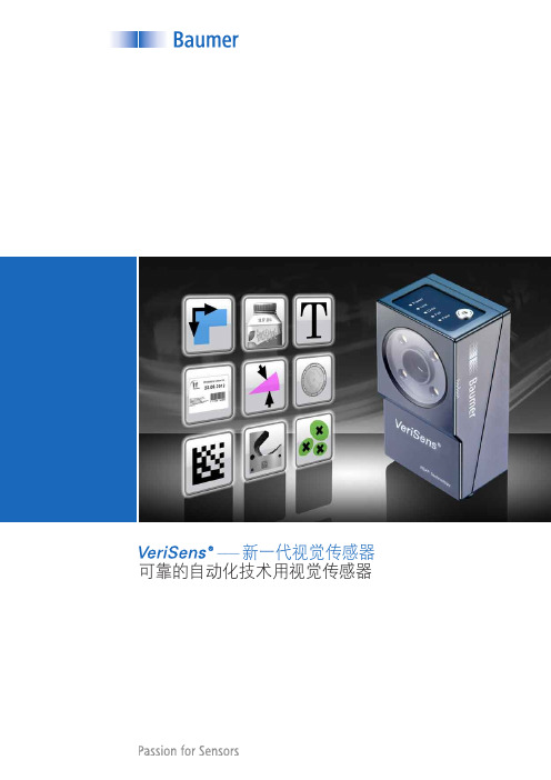
Baumer 堡盟视觉传感器应用
n 采用
技术实现强大的360°目标识别功能,充分满足拿放应用要求
n 通过校正透视扭曲和镜头扭曲进行坐标转换
n 可自由定义的处理接口和灵活的结果连接
n 用户等级和密码保护功能,防范未经授权的更改
通过坐标转换,实现精确定位
采用
XF-100 / XF-200,无论零件是否发生旋转,其定位值可输出在
用户定义的坐标处。要输出精确位置,需要在坐标转换过程中对透视扭曲和
以太网,RS485
代码 10 mm
ID-110 3.5
以太网
文本,代码 10 mm
矩阵码 可在任何旋转位置读取矩阵码。质量测定标准为ISO / IEC 15415和AIM DPM-1-2006;读取 结果通过处理接口输出并可与设定值比较。
采用默认参数的典型计算时间(*由于被检零件的特征不同,计算时间可能显著增加)
15 ms* 25 ms* 20 ms* 35 ms*
读取食品包装上“best-before date”(保质期),字 符读取结果通过处理接口输出并与设定值比较。
20 ms* 35 ms*
读取药品包装上的 条形码
读取压铸件上的激光刻写 矩阵码
读取结果通过处理接口输出至机器控制系统。
即使在要求苛刻的应用中,功能强大的
算法仍然能够实现高速读码,例如识别金属表面
上的DataMatrix码、具有透视扭曲、低对比度或码元丢失等情况。
系列
ID-110 多功能读码器
Best before date • Shelf life
为您带来的好处
n 零件无需机械引导 n 快速实施检查任务 n 目标定位功能允许同时检测多个产
品特征
轮廓处理 —— 采用
堡盟

技术实现人类的创想“我们凭借自己的技术,实现精准的理念,并以此使人类实现对安全的简约生活的追求。
”堡盟集团堡盟集团管理层(从左到右)Dr. Axel Vietze—过程自动化Dr. Oliver Vietze—CEO & 主席Rainer Klug—运营Severino Bruno—财务Ruediger Foerster—销售和市场成功迈向未来发展至今,堡盟集团(Baumer Group)已是一家国际领先的传感器和系统制造商。
堡盟集团的历史可以追溯到赫伯特.堡盟(Herbert Baumer),集团的先驱者。
他在1952年建立堡盟电子,是一家专业生产精密仪器的企业,起初专业生产微动开关。
1964年,赫尔穆特.维茨(Helmut Vietze)接管公司。
70年代初,他作为一个富有远见的企业家,带领堡盟进入传感技术领域,并将堡盟从之前的小企业发展成为一个国际性的集团公司。
以持续性和可靠性为基准的企业方针造就了堡盟50多年的成功和持续的增长。
2007年,公司掌管权交付下一代手中,我们制订新的公司发展策略。
我们未来的战略是:堡盟集团的所有分公司将实现品牌的全球同一化,我们在全球范围内积极开拓新的销售机构。
未来,在经济管理和技术开发方面,我们将根据堡盟的传统价值:亲近客户,注重质量,精益求精,开拓创新,设立标准和规定。
我们将保持家族企业的独立性。
奥利弗.维茨博士(Dr.Olver Vietze)首席执行官 & 主席堡盟集团总部位于瑞士Frauenfeld , 全球在16个国家设有34个分支机构,共约有2000名员工。
在过去的几十年里,堡盟作为传感产品制造商,以其技术创新、品质卓越在工业自动化和过程自动化行业赢得了崇高的声誉。
我们提供丰富的各属不同行业的标准产品,这些产品都是基于在多样化的传感器技术上。
我们的客户受益于我们能提供完整咨询和可靠服务的国际平台。
在与客户的紧密合作下,我们为其研发出兼备成本优势和效率优势的特殊的解决方案。
德国Baumer Gigabit千兆以太网相机
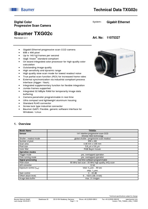
Digital ColorProgressive Scan CameraSystem: Gigabit Ethernet Baumer TXG02cRevision 2.1 Art. No: 11075327•Gigabit Ethernet progressive scan CCD camera•656 x 490 pixel•Up to 140 full frames per second•GigE Vision® standard compliant•On board integrated color processor for high quality color calculation•Outstanding image quality•High sensitivity and dynamic range•High quality slow scan mode for lowest readout noise •True partial scan function (ROI) for increased frame rates •External synchronization via industrial compliant process interface (trigger / flash)•Integrated supplementary function for flexible integration •Jumbo frames supported•Integrated 32 MByte RAM for temporarily image data buffering•Camera parameter programmable in real-time•Ultra compact and lightweight aluminum housing•Standard RJ45 connector•Screw-lock type industrial connector•Baumer-GAPI: Flexible, generic software interface forWindows / Linux1. OverviewModel Name TXG02cSensor 1/4“ interline progressive scan CCDEXview HAD technology Shutter / readout mode global shutter / progressive scan readout Number of pixel 656 x 490Scan area 4.46 mm x 3.80 mmPixel size 5.6 µm x 5.6 µmColor filter RGB Bayer mosaicOperation modesTrigger mode yes, overlapped operationFree running mode yes, overlapped operationSignal processing real-time software programmablePixel clock 60 MHz fast scan / 30 MHz high quality (HQ) scan A/D converter 12 bitExposure control (t exp) total: 4 µsec .. 60 secstep: 1 µsec Gain control 0 .. 20 dBOffset (black level) 0 .. 1023 LSB (14 bit)Image data buffer max. 31 imagesImage acquisitionCamera image format modes Format(pixel) Gen<I>CamstandardFormatIDPixelformatPixelclockMHzFramesper sec.*)t readoutBayerRG8BayerRG12Mono8YUV411 PackedYUV422 Packed **)YUV444 PackedRGB8 PackedFull frame HQ slow 656 x 490 Vendorspecific00BGR8 Packed30 70 15 msecBayerRG8BayerRG12Mono8YUV411 PackedYUV422 Packed **)YUV444 PackedRGB8 PackedFull frame fast 656 x 490 yes 01BGR8 Packed60 140 8 msecStandard featuresImage size controlsPixel format BayerRG8, BayerRG12, Mono8, YUV411 Packed, YUV422 Packed, YUV444 Packed,RGB8 Packed, BGR8 PackedTest image selector yes, in all modesOff, GreyHorizontalRamp, GreyVerticalRamp,HorizontalLineMoving, VerticalLineMovingHorizontalAndVerticalLineMovingPartial scan yes, format freely programmable in all modesAnalog controlsGain yesBlack Level (Off set) yesGamma noAcquisition and TriggerAcquisition mode ContinuousAcquisition frame rate yes, ON / OFF (only in freerunning mode)0 .. 829 Hz,step: 0.01 HzTrigger source HardwareTrigger (Line0), SoftwareTrigger, CommandTrigger (ActionCommand), All or Off Trigger delay 0 .. 2 sec, 512 trigger can be tracked,step: 1 µsecSequencer noDigital I/OLines Input: Line0, Output: Line1Line source (outputs only) Line1: Off, ExposureActive, Timer1, ReadoutActive, User0,TriggerReady, TriggerOverlapped, TriggerSkippedLine debouncer yes, low and high signal separately selectable0 .. 5 msecstep: 1 µsecEvent GenerationEvents GigEVisionError, Heartbeattimeout, EventLost, Line0RisingEdge, Line0FallingEdge,Line1RisingEdge, Line1FallingEdge, ExposureStart, ExposureEnd, FrameStart, FrameEnd,TriggerReady, TriggerOverlapped, TriggerSkippedEvent Notification yes, ON / OFFCounters and TimersFramecounter yes, 232can be set by userTimer yes,TimerSelector: Timer1TimerTriggerSource:Off, Input: Line0, SoftwareTrigger, CommandTrigger (ActionCommand),ExposureStart, ExposureEnd, FrameStart, FrameEnd, TriggerSkippedTimerDelay: 0 µsec .. 2 sec, step: 1 µsecTimerDuration: 10 µsec .. 2 sec, step: 1 µsecLUT ControlsLUT selector noDefect pixel correction (custom) yes, ON / OFFDefect pixel list (custom) yes, max. 256 pixel coordinates (x, y) can be stored GigEVisionTransportLayerPayLoadsize 4 Byte .. 648.400 ByteTransmissionDelay (custom) 0 .. 232-1 ticksUserSetsUser set selector Default (factory settings / read only)UserSet1, UserSet2, UserSet3 (read and write) UserSetDefaultSelector yes, define the start up “UserSet”Advanced featuresTime stamp function yes, 64 bittick = 32 nsecAsynchronous message channel yesConcatenation function yesUser defined identifier yes, user programmable permanent identifierActionCommand yes, ID 0 = TriggerDeviceTemperature noData quality at 20 °C, gain = 1, exposure time = 32 msec,full frame mode, slow scanReadout noise σ < 0.5 LSB (8 bit) typicalDynamic range typical > 54 dBOptical interface C-Mounton request: CS-MountOptical filter Hoya E-CM500Son request: dust protection, daylight filter or no filterProcess interface functionsAsync. Trigger yes, trigger mode operation,“Off”, “software trigger”, “hardware trigger”, “command trigger” or “all” separately selectable(overtriggered signals and trigger signals during the readout timewill be notified in the received image header)Exposure Active (External flash sync)yes,delay_value (t delay flash) ≤ 4 µsec, duration_value (t duration): slow mode = t exp + 28 µsec fast mode = t exp + 14 µsecUser Output yes, ON / OFF Timer yes, Timer1 Software reset yes, delay up to 102 msecAsynchronous reset Full frame slowfast delay up to 2,5 msec 1,3 msecImage info header yesElectrical interfaceData / control standard single cable 1000 Base-T,Cat6 recommended / minimum Cat5eoption: screw lock type connectorPower VCC: 8 VDC .. 30 VDCI: 450 mA .. 120 mAPower consumption approx. 3.6 WattDigital input Line 0: trigger signal, opto decoupledU IN(low) = 0 .. 4.5 VDC, U IN(high) = 11 .. 30 VDCI IN = 6 .. 10 mA / 7 mA typicalrising edge (invert = false) ****)min. impulse length (t min): 2 µsectrigger delay out of t readout (t delay trigger): 1 µsecmax. trigger delay during t readout (t delay trigger): slow mode = 28 µsecfast mode = 14 µsec Digital output Line 1: opto decoupledU EXT = 5 .. 30 VDC / 24 VDC typical, I OUT = max. 16 mAhigh active (invert = false) ****)LED 1:2: green:yellow:green:green flash:yellow:yellow/red flash:Power onReadout activeLink Phy (1 GBit)Ethernet RXEthernet TXEthernet RX/TXEnvironmentalStorage temperature -10 °C .. +70 °COperating temperature +5 °C .. +50 °C ****)between +26 °C .. +50 °C, note the max. housing tem perature Housing operating temperature max. +50 °CHumidity 10 % .. 90 % non condensingConformity CE, FCC Part 15 class B, UL, RoHS compliantHousing aluminum, IP40Dimensions 36 x 36 x 48 mm3Weight < 90 g1000 Base-T interface 1000BASE-T (1000 Mbit / sec)Ethernet IP configuration persistent IP / DHCP / LLAStream channel packet size 576 Byte (default) .. 65535 Bytejumbo frames supportedInterpacketgap 0 .. 232-1 ticksMulticast function yesResend function yesBaumer-GAPI SDK with supported OS socket driver and Baumer filter driver / SoftwareSDK for Windows XP (32 bit) / Windows Vista (32 bit / 64 bit) / Windows 7 (32 bit / 64 bit) /Linux Kernel 2.6.xx (64 bit / 32 bit)GigE Vision® compatible programs and image processing libraries supportedWindows / Linux depending on the actually driver software is used*)maximum frame rate in free running mode, effective frame rate depending on camera image format mode settings and set exposure time (t exp < t readout)**)default pixel format***) can be inverted via software****)housing temperature is limited by CCD sensor specification2. Camera Factory Settings after Camera Start-upCamera factory settings after camera start-up Operation modes free running modeSignal processingExposure control 32 msecGain control factor 1 = 0 dBOffset (black level) 0Image acquisitionCamera image format mode mode id = 01, full frame YUV422 PackedPartial scan function not activeAcquisition frame rate OffTimer OffTransmission delay 0 ticksTest image selector OffDefect pixel correction OnElectrical interfaceDigital input 1: Line0disabled, digital output set to low status (high impedance)invert = falseline source = Exposure Active Digital output 1: Line1disabledinvert = falsetrigger source = Line03. Timing Operation ModesTrigger Mode: start up timeTrigger Mode: trigger mode 0, overlapped triggerexposurereadouttriggerparameter *Frame n effectiveready for trigger **parameter *Frame n+1effectiveflasht exp < t readout : t earliest possible trigger (n+1) = t readout(n) - t exp(n+1)t exp > t readout : t earliest possible trigger (n+1) = t exp(n)t exp < t readout : t not ready (n+1) = t exp(n) + t readout(n) - t exp(n+1)t exp > t readout : t not ready (n+1) = t exp(n)* image parameter: offsetglobal gain modepartial scan** signal will be notified as event “TriggerReady” and is not available as digital outputTrigger Mode: trigger mode 0, overlapped trigger , when t exp (n+2) > t exp (n+1)exposurereadouttriggerready for trigger **flasht exp < t readout : t earliest possible trigger (n+1) = t readout(n) - t exp(n+1)t exp > t readout : t earliest possible trigger (n+1) = t exp(n)t exp < t readout : t not ready (n+1) = t exp(n) + t readout(n) - t exp(n+1)t exp > t readout : t not ready (n+1) = t exp(n)parameter *Frame n effectiveparameter *Frame n+1effective* image parameter: offset global gain modepartial scan** signal will be notified as event “TriggerReady” and is not available as digital outputTrigger Mode: trigger mode 0, overlapped trigger , when t exp (n+2) < t exp (n+1)exposurereadouttriggerready for trigger **flashFrame n+2not started / overtriggeredt exp < t readout : t earliest possible trigger (n+1) = t readout(n) - t exp(n+1)t exp > t readout : t earliest possible trigger (n+1) = t exp(n)t exp < t readout : t not ready (n+1) = t exp(n) + t readout(n) - t exp(n+1)t exp > t readout : t not ready (n+1) = t exp(n)parameter *Frame n effective parameter *Frame n+1effective* image parameter: offsetglobal gain modepartial scan** signal will be notified as event “TriggerReady” and is not available as digital outputFree Running Mode: overlapped operationexposure readoutparameter *Frame n-1parameter *Frame nparameter *Frame n+1flash* image parameter: offsetglobal gainmodepartial scan4. Housing5. Connectors / Electrical Interfaces5.1 Pin assignment:*) resistor must be used, I OUT = 16 mA by = 24 VDC recommended, drawing shown above example for using high active signal *) shielded trigger / flash cable should be used and orderedseparatelyTechnical Data TXG02cTechnical specifications subject to changeBaumer Optronic GmbHBadstrasse 30 DE-01454 Radeberg, Germany Phone +49 (0)3528 4386 0 Fax +49 (0)3528 4386 86 Last change: 08.06.2011 Page 11 / 12 Version: TDS_TXG02c_v20e_110608 5.2 Flash sync sample U EXT = 24 VDC high active:t ON time = typ. 2 µsect OFF time = typ. 40 µsec OFFONTiming example:measurement condition U EXT = 24 VDC / I OUT = 16 mA R L = 1.5 kOhm5.3 Flash sync sample U EXT = 24 VDC low active:t ON time = typ. 2 µsect OFF time = typ. 40 µsec EXTTiming example:measurement condition U EXT = 24 VDC / I OUT = 16 mA R L = 1.5 kOhmEnd of Document。
Baumer产品选型手册

堡盟工业相机全面的产品组合堡盟产品组合■ 紧凑型工业相机,分辨率从VGA 直至800万像素■ Gigabit 千兆以太网、FireWire TM 和 CameraLink ® 接口 ■ 创新技术改进,例如以太网供电、Dual GigE 、 IP67相机、多I/O 等堡盟是创新型图像处理组件的全球领先制造商之一,提供广泛的适合各种应用的高品质工业相机。
我们的核心能力涉及传感器集成、信号处理、接口和驱动程序等所有视觉应用领域,确保将相机集成在相应的视觉系统中。
产品组合包括CCD 和CMOS 相机,分辨率从VGA 到800万像素不等。
数字相机采用各种标准接口,例如:Gigabit 千兆以太网、CameraLink ® 和 FireWire TM .■分辨率从VGA 直至500万像素■ 坚固型工业设计(尺寸:36 x 36 x 48 mm )■ 宽范围供电设计:8-30 VDC堡盟工业相机 技术不断创新,集成更加简单采用CCD 传感器的紧凑型GigE 相机在TXG 系列中,堡盟提供广泛的采用强大的CCD 传感器的GigE Vision ®相机。
其它功能,诸如多点传送、触发延迟、计时器、防回跳器和序列发生器,也更能优化系统集成。
GigE Vision ® 相机多 I/O 口GigE 相机这类相机提供3个附加输入输出(I/O ),从而提高了视觉系统集成的灵活性。
T XG以太网供电TXG 相机是满足GigE 网络应用要求的价格合理的单电缆解决方案。
该款相机简化的机械设计,提高了可靠性, 同时降低了整个相机系统的安装和维护成本。
适于不同镜头的套管由于相机的防护外壳上带有集成的C-Mount 接头,因此无论是相机的传感器及电子元件还是所有常见的标准镜头都可以得到安全保护。
■通过同一根以太网电缆实现数据传输和供电■ 提供堡盟PoE 电源交换机、供电器和触发设备■ 降低了安装和维护成本采用以太网供电(PoE )和CCD 传感器的GigE 相机■同时为相机和镜头提供保护■ 防水防尘,适合恶劣的环境条件■ 多种套管长度,适用于不同的标准镜头采用IP67外壳和CCD 传感器的GigE 相机这款防护等级为IP67的相机是专为在恶劣及苛刻环境中的应用而开发的。
Omron Microscan HAWK MV-4000智能相机配件清单说明书
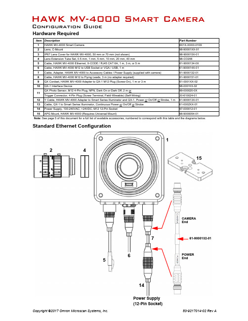
Hardware RequiredStandard Ethernet ConfigurationNote: See page 5 of this document for a full list of available accessories, numbered to correspond with this table and the diagrams below.HAWK MV-4000 Smart CameraConfiguration Guide61-9000132-01CAMERA EndPOWER End1547621415Power Supply (12-Pin Socket)Ethernet Configuration with Flying Leads15462158M12 to Flying Leads Cable, 3 m – 61-9000151-01Pin Signal Wire Color 1Trigger White 2Power Brown 3Input 2Green 4Input 1Yellow 5Output 1Grey 6Output 3Pink 7Ground Blue 8Input Common Red 9NC Black 10NC Violet 11Output 2Grey-Striped Pink 12Output Common Red-Striped BlueEthernet Configuration with QX-1 and NERLITE Smart Series Illuminator10911131547621415Power Supply (12-Pin Socket)Photo SensorNERLITE Smart Series IlluminatorEthernet Configuration with Y Cable for Illuminator Control and Camera Power154762121415Power Supply (12-Pin Socket)NERLITE Smart Series IlluminatorNERLITE Smart Series IlluminatorNERLITE Smart Series IlluminatorHAWK MV-4000 AccessoriesElectrical SpecificationsHAWK MV-4000-03, -03C, -13, -13C, -20, -20C, -50, -50COperating Voltage for the HAWK MV-4000 under Testing Conditions 24V Rated Current600 mA Operating Voltage Tolerance±10%See the HAWK MV-4000 Smart Camera Guide for full electrical specifications.+10-28VTriggerGround Trigger/New Master / Input 1 CommonQX-1 Interface Device – for use with the HAWK MV-4000 (Top View)QX-1 Trigger Connector (T) 4-pin SocketConnector T on the QX-1 Interface Device is the trigger connector.Connectors 1, 2, and 3 can be used to bus power and data as required by the application.PTVGA/USB Connector M12 12-Pin Plug10/1000 Base-T Connector M12 8-Pin X-Coded SocketDigital I/O and Power ConnectorM12 12-Pin SocketOutput 3Power TriggerInput CommonInput 2Input 3Input 1Output 1GroundOutput 2Output CommonAnalog OutputHAWK MV-4000 Part Number Structure HAWK MV-4000 part numbers follow the format 8ABS-LFFA-LPPP.8 = HAWK MV-4000 Smart Camera(A) Enclosure0 = No Lens Cover1 = 50 mm Lens Cover2 = 70 mm Lens Cover(B) Software = 1 (Machine Vision)(S) Sensor Type1 = VGA, Mono2 = 1.3 Megapixel, Mono3 = 2 Megapixel, Mono4 =5 Megapixel, Mono5 = VGA, Color6 = 1.3 Megapixel, Color7 = 2 Megapixel, Color8 = 5 Megapixel, Color(L) Lens (See table below)0 = No Lens1 = 2/3” Standard Def.2 = 2/3” High Def.3 = 1” High Def.(FF) Lens Focal Length00 = No LensXX = Focal Length (mm) (See Lens table below.)(A) Accessories = 0(L) Lighting = 0(PPP) License100 = AutoVISION Sensor101 = AutoVISION102 = AutoVISION + Visionscape103 = AutoVISION + Verification104 = AutoVISION + Visionscape + Verification。
basler相机常用参数

basler相机常用参数摘要:1.Basler 相机简介2.Basler 相机常用参数分类3.常用参数详细介绍3.1 分辨率3.2 帧速率3.3 曝光时间3.4 增益3.5 白平衡3.6 对焦3.7 图像旋转3.8 网络接口3.9 存储方式3.10 电源正文:一、Basler 相机简介Basler 是一家专注于研发和生产数字图像处理器和相机模块的公司,其产品广泛应用于工业、医疗、交通和安防等领域。
Basler 相机以其高性能、高品质和高可靠性而受到广泛好评。
二、Basler 相机常用参数分类Basler 相机的常用参数主要可以分为以下几类:1.成像参数:包括分辨率、帧速率、曝光时间等;2.信号处理参数:包括增益、白平衡等;3.对焦参数:包括对焦方式等;4.图像处理参数:包括图像旋转等;5.网络接口参数:包括网络接口类型等;6.存储参数:包括存储方式等;7.电源参数:包括电源类型等。
三、常用参数详细介绍3.1 分辨率分辨率是指相机传感器能够捕捉的图像的像素数量,通常用“万像素”表示。
分辨率越高,图像的细节越丰富,但同时数据量也越大,对图像处理器的性能要求也越高。
3.2 帧速率帧速率是指相机每秒能够捕捉的图像数量,通常用“帧/秒”表示。
帧速率越高,相机的实时性就越好,适用于对运动物体进行捕捉的场景。
3.3 曝光时间曝光时间是指相机传感器暴露在光线下的时间,通常用“毫秒”表示。
曝光时间越长,图像的亮度就越高,但同时也会增加运动的模糊度。
3.4 增益增益是指相机对输入信号进行放大的倍数,通常用“倍”表示。
增益越高,图像的亮度就越高,但同时也可能引入噪声。
3.5 白平衡白平衡是指相机对输入信号进行颜色校正的过程,以使得图像的白色看起来是真正的白色。
白平衡的设置会影响到图像的整体色彩效果。
3.6 对焦对焦是指相机调整镜头的位置,使得图像能够清晰地显示在传感器上。
对焦方式包括手动对焦和自动对焦两种。
3.7 图像旋转图像旋转是指相机将捕捉到的图像进行旋转,以便更好地适应特定的应用场景。
- 1、下载文档前请自行甄别文档内容的完整性,平台不提供额外的编辑、内容补充、找答案等附加服务。
- 2、"仅部分预览"的文档,不可在线预览部分如存在完整性等问题,可反馈申请退款(可完整预览的文档不适用该条件!)。
- 3、如文档侵犯您的权益,请联系客服反馈,我们会尽快为您处理(人工客服工作时间:9:00-18:30)。
N 西门子 SIMATIC® S7 功能模块 N 结果输出与设备控制用处理接口
N 可通过FTP检索、储存以及显示实时图像和错误图像 N 工作和调试用备份与恢复功能
N 以太网接口实现灵活的系统集成 N 通过网关和NAT支持实现远程访问
ID系列
ID-100 一维和二维码阅读器
DataMatrix (ECC 200, GS1)
1 ms
区域计数 计算图像区域中连续可见亮区或暗区的个数。
5 ms
模板对比 将工作区域与自学习模板进行比较。
0.4 ms
识别
条形码 读取条形码。质量测定标准为ISO / IEC 15416;读 取结果通过处理接口输出并可与设定值比较。
安全可靠
N 防护等级为 IP67,坚固金属外壳 N 通过用户等级 / 密码保护,确保安全操作
应用
就位与完整性检查 目标定位与位置检测 数字和字符读取 条形码和矩阵码读取
Fig. showing original size
ID 系列 可靠的识别用读码器
ID-100 读取一维和二维码
ID-110 读取文本、一维和二维码
Best before: ~ Best by: ~
Freshness date ~
Expiration date ~ Health mark ~
Identification mark ~ Approval number ~ DE BY 000 EG ~
Use by: ~ Use-by date ~ PAO ~ Period after opening ~ 12 M ~
读取食品包装上“best-before date”(保质期), 字符读取结果通过处理接口输出并与设定值比较。
CS系列
CS-100 产品检查和分选
快速、方便地检查产品特征,并且处理稳定性高。
CS-100
N 采用
技术实现360°目标识别,确保在不同位置进行目标定位
N 强大的就位检查和完整性检查功能
N 能同时检查最多32种特征
可视化Web界面
N 通过标准Web浏览器显示图 像,无需插件
N 轻松切换产品任务 N 支持所有操作系统,包括
Windows CE / XP Embedded
集成 —— 简单而灵活
N 嵌入式测试环境确保了在实际生产之前进行可靠的性能测试
N 所有产品均配备嵌入式
产品模拟器
N 提供五种灵活的数字输入和数字输出,便于您在实际应用中灵活配置 N 编码器接口实现基于路径的触发和剔除
ID-100 ID-110 CS-100 XF-100 XF-200 XC-100 XC-200
特征比较
对比度 计算工作区域内的对比度。
ID-100 ID-110 CS-100 XF-100 XF-200 XC-100 XC-200
0.1 ms
面积 测定图像中亮区或暗区面积。测定总面积或 最大连续面积。
基于边缘的目标定位 基于一个边缘或两个互成直角的边缘进行目 标定位及其旋转位置测定。随后的所有特征 检查可根据测定的位置进行校准。
环状目标定位 环状目标定位及其旋转位置测定。随后的所 有特征检查可根据测定的位置进行校准。
基于文本框的目标定位 工作区域内的文本框定位及其旋转位置测 定。在任务执行期间文本可能变化。随后的 所有特征检查可根据测定的位置进行校准。
N 采用可自由定义的5路输出进行目标物分选
N 编码器接口实现基于路径的触发和剔除
特征检查
基于轮廓的目标定位 根据目标物轮廓进行定位及其旋转位置测定。随后的所有特征检查可根据测定的位置 进行校准。
50 ms
亮度 测定工作区域内的平均亮度。
轮廓点计数 测定工作区域内的轮廓点数量。
0.1 ms
1 ms 分辨率为752 × 480 px 时,采用默认参数的典型计算时间(由于被检目标物的特征不同,计算时间可能显著增加)
读取药品包装上的 条形码
读取压铸件上的激光刻写 矩阵码
读取结果通过处理接口输出至机器控制系统。
即使在要求苛刻的应用中,功能强大的
算法仍然能够实现高速读码,例如识别金属表面上的
DataMatrix码,可应对透视扭曲、低对比度或码元丢失等情况。
ID系列
ID-110 多功能读码器
Best-before date ~ Shelf life ~
应用示例:
XF-200用于标签监控
是否有包装内容物?
所选择的标签是否正 确?
XF-200
N 增加了一维 / 二维码和文本识 别功能(OCR / OCV)
标签定位及其旋转位 置是否正确?
是否正确打印 “best-before date” (保质期)? 条形码所含信息是否 正确?
XC Series
XC-100 / 200 适用于智能型系统解决方案的视觉系统
矩阵码 可在任何旋转位置读取矩阵码。质量测定标准为ISO / IEC 15415和AIM DPM-1-2006;读取 结果通过处理接口输出并可与设定值比较。
轮廓比较 将自学习目标物的轮廓与当前目标物的轮廓进行比较。
15 ms 50 ms 20 ms 35 ms 1 ms
分辨率为752 × 480 px 时,采用默认参数的典型计算时间(由于被检目标物的特征不同,计算时间可能 显著增加)
CS系列
CS-100 应用示例
就位检查
N 在任意位置(360°)对目标 进行检测
N 目标物特征的二维检查
瓶盖检查,以确保饮料瓶的卫生质量
自动化装配机中的SMD部件检查(胶带 和卷轴)
完整性检查
N 检查目标物的形状和几何特征 N 每个任务可同时计算最多32
种产品特征
电子元件连接器的就位检查与目标定位
注塑成型塑料件的分离检查
定位和位置检测
N 送料设备中的目标物位置检测 N 安装和搬运过程中的定位监控
在饮料罐360°旋转位置中,监控拉环
探测铆钉在送料设备中的位置是否正确
特征检查 距离 测定两边缘之间的距离。
圆 测定直径、位置和相比参照圆的圆度。
轮廓比较 将自学习目标物的轮廓与当前目标物的轮廓进行比较。
N 增加了一维 / 二维码和文本识 别功能(OCR / OCV)
模块化系统设计
3
4
1 5
2
1 集成频闪控制器 2 直接连接外部光源 3 自由选择镜头 4 模块化光源连接系统 5 自由选择光源
采用
视觉系统进行特征检测
目标定位
基于轮廓的目标定位 根据目标物轮廓进行定位及其旋转位置测 定。随后的所有特征检查可根据测定的位置 进行校准。
特征检查 基于文本框的目标定位 工作区域内的文本框定位及其旋转位置测定。在任务执行期间文本可能变化。随后的 所有特征检查可根据测定的位置进行校准。
文本 读取数字和字符。字符读取结果通过处理接口输出并可与设定值比较。
条形码 读取条形码。质量测定标准为ISO / IEC 15416;读取结果通过处理接口输出并可与设定 值比较。
0.2 ms 0.5 ms 1 ms
XF系列
XF-100 / 200 质量检查与识别
功能强大的视觉系统。 操作简单可比视觉传感器。
XF-100
N的360°目标识别
N 通过校正透视扭曲和镜头扭曲进行坐标转换
N 自定义处理接口和灵活的结果连接
N 用户等级和密码保护功能,防范未经授权的更改
码读取性能。
RSS-14 Stacked ~ RSS-14 Stacked Omnidir
ID-100
N 可读取打印码和直接部件打标码(DPM) N 可同时读取多种码(一维 / 二维码,包括GS1) N 无论位置是否旋转,也能顺利读码并验证 N 根据ISO / IEC 15415 / 15416和AIM DPM-1-2006对标码进行质量控制 N 使用RS485或以太网(TCP/IP)轻松实现与PLC连接
~
PDF417 ~ 2/5 Industrial ~ 2/5 Interleaved
~
Codabar ~ Code 39 ~ Code 93 ~ QR
~
Code 128 ~ PharmaCode ~ EAN 13 ~
EAN 13 Add-On 2 ~ EAN 13 Add-On 5 ~
EAN 8 ~ EAN 8 Add-On 2 ~ EAN 8 Add-On 5 ~ UPC-A ~
—— 更直观的新一代视觉系统 自动化技术可信赖的视觉系统
视觉系统 用于自动化技术
用户界面友好
N 所有
视觉系统均采用直观用户界面——设置简单,4步即可完成
N 新功能:用于外部照明的全集成频闪控制器(XC系列)
功能强大
N 采用
技术实现可靠的 360º 目标定位
N 新功能:C-Mount设计(分辨率高达2 MP)
UPC-A Add-On 2 ~ UPC-A Add-On 5 ~
UPC-E ~ UPC-E Add-On 2~
UPC-E Add-On 5 ~ RSS Limited ~
RSS Expanded ~ RSS Expanded Stacked ~
即使在苛刻的应用条件下,也表现出优异RSS的-14 ~一RSS-维14 Tru和ncated二~ 维
特征检查
条形码 读取条形码。质量测定标准为ISO / IEC 15416;读取结果通过处理接口输出并可与设定 值比较。
矩阵码 可在任何旋转位置读取矩阵码。质量测定标准为ISO / IEC 15415和AIM DPM-1-2006;读取 结果通过处理接口输出并可与设定值比较。
20 ms 35 ms
分辨率为752 × 480 px 时,采用默认参数的典型计算时间(由于被检目标物的特征不同,计算时间可能 显著增加)