391KD05NX中文资料
Nx系列软起动器产品说明书

Nx系列软起动器产品说明书数恩,控制和保护您的电机Shanghai SHUEN Electrical Technology Co.,ltd电气参数本产品须由有资格的电工依照安全规范进行安装、试运行和维护等操作;本产品使用的电压具有危险性,可能导致他人重伤或致死,在设备电源接通后或运行中时严禁触摸端子。
即使设备已经关掉电源,输出端子可能仍带有电压;本产品应在符合产品额定规格下使用,使用前请检查产品或设备的电源、电机和频率等参数是否正确。
本产品出厂前已经过绝缘测试,不正确的摇表测试可能会导致产品损坏或寿命缩短。
主回路控制回路仅外控键盘使用5.5~37k W (194)指示灯释义运行时序图面板参数软起时间旋钮:用来调节软起动器的软起动时间,范围为1~20s ,时间设置越长,软起起动过程越平缓,有利于减少对电网的冲击。
软停时间旋钮:用来调节软起动器的软停车的时间,范围为0~20s ,软停车功能在某些水泵应用场合,可以有效避免水泵停止时所产生的“水锤效应”。
当旋钮调节为0s 时,则表示电机停车方式为自由停车方式,软起立刻停止输出。
起始电压旋钮:用来调节软起动器的起动起始电压,范围为40%~70%,电机起动时需克服静止状态的摩擦力,适当调高起始电压可获取更大的起动力矩。
用户应参照实际负载情况,配合起动和停止时长,获取最佳的平稳起动效果。
接线参数本图纸内容仅供参考使用L1L2L3PV两线控制SARUNCOM STOPRA 旋钮/开关(自锁型)启停方式启动输入RQ RB 工作状态指示RUN COM STOPRA 按钮启停方式启动输入RQ RB工作状态指示SB1SB2三线控制停止输入本图纸内容仅供参考使用本图纸内容仅供参考使用此为选配件说明(标准产品不含),通过RJ45接口(需网线)连接,如有需要请联系厂家。
外引键盘开孔尺寸代码查看、修改方法说明操作面板采用三级菜单结构进行参数设置等操作。
三级菜单分别为:功能参数组(一级菜单)→功能码(二级菜单)→功能码设定值(三级菜单)。
稱重顯示控制器 KM05 說明書

稱重顯示控制器KM05說明書2010年6月版●使用前請仔細閱讀本產品說明書●請妥善保管本產品說明書,以備查閱創唯實業有限公司目錄1.0 概述 (1)1.1主要特點 (1)1.2技術指標 (1)1.2.1 負載能力 (1)1.2.2 性能 (1)1.2.3 電源 (1)1.2.4 溫度和濕度 (2)1.2.5 外形尺寸(尺寸單位為毫米) (2)2.0 安裝 (2)2.1儀錶固定 (2)2.2電路連接 (3)2.2.1 後視圖 (3)2.2.2 電源連接 (3)2.2.3 荷重元連接 (3)2.2.4 串列口通訊線連接 (3)2.2.5 類比輸出連接 (4)2.2.6 繼電器控制輸出 (4)3.0 顯示面板 (5)4.0 重量標定 (5)4.1參數確定 (5)4.2標定步驟 (6)5.0 類比輸出類型選擇與調整 (7)5.1選擇輸出類型 (7)5.2選擇類比輸出對應的重量範圍 (7)5.3調整類比輸出的底端與頂端 (8)5.4恢復類比輸出的底端與頂端 (8)6.0 儀錶工作參數選項 (9)6.1進入工作參數選項 (9)6.2功能F2選項參數組內容 (9)7.0 繼電器輸出 (9)7.1繼電器輸出設置步驟 (10)8.0 設置串列介面 (10)8.1設置步驟 (10)8.2選擇匯流排方式 (11)9.0 開機自檢資訊 (11)10.0 部分參數快速查看 (11)11.0 錯誤提示資訊 (12)12.0 儀錶的維護 (12)12.1儀錶的常規維護 (12)12.2一般故障排除 (12)附錄通訊協定1-命令方式 (14)資料格式 (14)附錄通訊協定2-連續發送方式1 (16)附錄通訊協定3-連續發送方式2 (17)1.0 概述KM05工業控制領域(或其他需要類比輸出的應用場所)的稱重顯示控制器,集重量顯示與類比信號輸出於一體,前端信號處理採用高精度的24位專用A/D轉換器,類比信號輸出採用16位元的D/A轉換器。
PHOENIX CONTACT 5孔绿色插针5-pos版商品说明书

Extract from the onlinecatalogPCV 4/ 2-G-7,62Order No.: 1804687The figure shows a 5-pos. version of the producthttp://eshop.phoenixcontact.de/phoenix/treeViewClick.do?UID=1804687Header, Nominal current: 20 A, Nom. voltage: 400 V, Pitch: 7.62 mm, Number of positions: 2, Color: green, Assembly: Solderinghttp://Please note that the data givenhere has been taken from theonline catalog. For comprehensiveinformation and data, please referto the user documentation. TheGeneral Terms and Conditions ofUse apply to Internet downloads. Technical dataDimensions / positionsPitch7.62 mmDimension a7.62 mmNumber of positions2Pin dimensions 1 x 0,8 mmHole diameter 1.3 mmTechnical dataInsulating material group IRated surge voltage (III/3) 6 kVRated surge voltage (III/2) 6 kVRated surge voltage (II/2) 6 kVRated voltage (III/2)630 VRated voltage (II/2)630 VConnection in acc. with standard EN-VDENominal current I N20 ANominal voltage U N400 VMaximum load current20 AInsulating material PAInflammability class acc. to UL 94V0Certificates / ApprovalsCertification BV, CSA, CUL, DNV, GL, GOST, LR, RS, ULCSANominal voltage U N300 VNominal current I N20 ACULNominal voltage U N300 VNominal current I N35 AULNominal voltage U N300 VNominal current I N35 AAccessoriesItem Designation DescriptionAssembly1827570BF-PC 4Mounting flange, is snapped onto the left and right of the headers,for screw connection with PC 4/...-STF-7.62Marking1051993B-STIFT Marker pen, for manual labeling of unprinted Zack strips, smear-proof and waterproof, line thickness 0.5 mm0804549SK 7,62/3,8:FORTL.ZAHLEN Marker card, printed horizontally, self-adhesive, 10-section markerstrip, 12 identical decades marked 1-10, 11-20 etc. up to 91-99,sufficient for 120 terminal blocks0805153SK 7,62/3,8:SO Marker card, special printing, self-adhesive, labeled acc. tocustomer requirements, 12 identical marker strips per card, max.25-position labeling per strip, color: white0803906SK U/3,8 WH:UNBEDRUCKT Unprinted marker cards, DIN A4 format, pitch as desired, self-adhesive, with 40 stamped marker strips, 185 mm strip length, canbe labeled with the CMS system or manually with the M-PENPlug/Adapter1600027CP-HCC 4Coding profile, Color: redAdditional productsItem Designation DescriptionGeneral1848892PC 4 HV/ 2-ST-7,62Plug component, Nominal current: 20 A, Nom. voltage: 800 V,Pitch: 7.62 mm, Number of positions: 2, Connection type: Screwconnection, Color: green1882379PC 4 HV/ 2-STF-7,62Plug component, Nominal current: 20 A, Nom. voltage: 800 V,Pitch: 7.62 mm, Number of positions: 2, Connection type: Screwconnection, Color: green1804904PC 4/ 2-ST-7,62Plug component, Nominal current: 20 A, Nom. voltage: 400 V,Pitch: 7.62 mm, Number of positions: 2, Connection type: Screwconnection, Color: green1828249PC 4/ 2-STF-7,62Plug component, Nominal current: 20 A, Nom. voltage: 400 V,Pitch: 7.62 mm, Number of positions: 2, Connection type: Screwconnection, Color: green1840191PCC 4/ 2-ST-7,62Plug component, Nominal current: 20 A, Nom. voltage: 400 V,Pitch: 7.62 mm, Number of positions: 2, Connection type: Crimpconnection, Color: greenDiagrams/DrawingsDrilling plan/solder pad geometryDimensioned drawingAddressPHOENIX CONTACT Inc., USA586 Fulling Mill Road Middletown, PA 17057,USA Phone (800) 888-7388Fax (717) 944-1625© 2010 Phoenix Contact Technical modifications reserved;。
钢铁大侠Dixon A540系列地面接线器说明书

A540 SERIES GROUND CLAMPContentsOverview (2)Features (2)Technical Specifications (3)Installation (6)Maintenance (8)Replacement parts (8)Operation (9)Warranty (9)Sales and Service Contacts (10)OverviewThe A540 Series ground clamps are key to creating a quality temporary connection for antistatic grounding applications. The clamp features three teeth to penetrate dirt, corrosion, and road grime when in use. The teeth are constructed of stainless steel to ensure lasting operation, and isolated from the clamp handle to allow operators to establish ground and a ground-verification signal in a single clamp action. The A540 also includes a high durability cable and junction box for convenient wiring access during installation and maintenance.Common applications for the A540 series ground clamp include:•Tank truck and Rail car loading facilities•Drum and barrel filling sites•Loading of stationary tanksFeatures•Clamp tethered to cable by stainless steel strap to protects connection from strain and wear. •Pull-out resistant cord grip on junction box holds cable tighter the harder it is pulled. •Junction box creates convenient service point for hazardous location installations.•Coiled cable for compact storage.•Strong clamping force to penetrate grime and remain connected during loading process. •Can provide ground and a ground-verification signal in a single clampTechnical SpecificationsMIN MAX NOMINAL AMBIENT TEMPERATURE -40°C 90°C -JUNCTION BOXHEIGHT 10.75 in. [27.3cm] INCLUDES STRAIN RELIEFWIDTH 3.0 in. [7.62cm]DEPTH 3.0 in. [7.62cm]WEIGHT 5 lbs. (2.27 kg)INGRESS PROTECTION Weatherproof, raintight, and dust tightCONDUIT ENTRIES ONE ¾” TRADE SIZE HOLE + FACTORY INSTALLED CABLE ONBOTTOMSUITABLE FOR INSTALL IN HAZARDOUS LOCATIONS: Class I, Division 1 & 2, Groups B, C, and D hazardous locationsClass II, Division 1 & 2, Groups E, F, and G hazardous locationsClass III hazardous locationsSUITABLE FOR CONNECTION TO HAZARDOUS LOCATIONS: Class I, Division 1 & 2, Groups A, B, C, and D hazardous locationsClass I, Zone 0, 1 & 2, Groups IIC, IIB, and IIA hazardous locationsCABLELENGTH 25 ft. stretched [7.6m] (Standard; other lengths available) DIAMETER 0.4 in. [1.0cm]WEIGHT 2.5 lbs. [1.13kg]; 0.1 lbs. PER FOOT [0.15g per meter] JACKET MATERIAL Thermoplastic Elastomer, resistant to harsh environments. RESISTANCE 0.14Ω (6mΩ/foot)RECOMMENDED WIREBETWEEN CONTROLLER ANDA54018 GA Stranded copper wire (THHN)AccessoriesGround Verification Monitor:The A240 series ground verification monitors are designed to mitigate the danger of static buildup by verifying the presence of a high quality and reliable earth-ground bond. With the presence of a ground path for static to dissipate, loading and unloading of flammable or combustible liquids can be done safely. The A240 monitor verifies the bond is of sufficient quality to prevent static buildup. Internal indicators inform the operator whether the process connection is safely grounded and internal relay contacts may be used to interlock operations until a safe earth bonding has been established.Sealing Fitting:Sealing fittings are required within 18 inches of each enclosure entry used. These seal conduits from passing hazardous vapors or propagating flame. Sealing fittings are installed in-line with conduit, then filled with sealing compound once wiring has been installed and verified. Downstream junction boxes containing Intrinsically Safe circuits may be serviced without danger.¾” NPT Vertical Seal fitting with nipple; P/N: 30192ALNote: Actual color may differWiring DiagramInstallationINSTALLATION MUST BE COMPLETED BY QUALIFIED PROFESSIONALA540 Series ground clamps are suitable for installation and use in ordinary and specific hazardous locations (listed in technical specifications section) as defined by NEC NFPA70 and IECEx standard 60079. Installation to be performed by a qualified professional.MechanicalIt is recommended to wall mount the unit using stainless steel or galvanized steel hardware suitable for the monitor’s weight and wall material.ing the bolt pattern provided below, locate a sturdy area, large enough to install the junctionbox.For greatest environmental resistance it is recommended to mount the junction box in theorientation shown. Keep in mind the coiled cable will hang below the box, and the clamp must be stored in an ungrounded position. The enclosure can withstand rain and sun exposure butwill last longer when protected from the elements.2.Level the bolt pattern and drill two holes marked on the pattern.3.Have another person lift the junction box into position in front of the drilled holes.4.Insert the two anchors or bolts into the two mounting holes shown below.5.Tighten all the screws and ensure that the junction box is secure.Electrical•To be installed per NEC NFPA70 requirements for U.S. installations.•Installation in other regions must conform to local electrical codes. Instructions provided below are general guidelines and may not cover local requirements.1.Remove the lid from the A540 junction box.2.Run conduit to junction box. Ensure conduit has sealing fitting at feeder end if installation is inhazardous location.Conduit connection should be sealed from water intrusion through either rubber washers,caulking, or other sealing means.3.Pull cable from process controller into A540 junction box.4.Refer to wiring diagram above, as well as documentation for process controller to properly wirethe process controller to the A540 ground cable.5.Reinstall lid onto junction box.6.Designate an ungrounded location to store the ground clamp while not in use. It is critical thatthe ground clamp be ungrounded while not in use. Storing in a grounded state can lead tounsafe loading conditions.7.Verify proper functionality of system by testing before putting into service.MaintenanceSERVICE SHOULD BE COMPLETED ONLY BY A QUALIFIED HAZARDOUS LOCATION TECHNICIAN. REPLACE PARTS WITH GENUINE DIXON OR APPROVED EQUIVALENT PARTS; SUBSTITUTION MAY IMPAIR INTRINSIC SAFETY.The A540 has few parts that will require regular maintenance and is designed for long service periods. Unsheltered units should be serviced in dry weather to prevent rainwater from entering the enclosure and minimize moisture exposure.1.If the ground connection is becoming intermittent, it is advised to inspect the clamp and cable.2.Dulling of the clamp teeth may be a sign that the clamp has reached the end of its usable lifeand should be replaced. Contact Dixon for replacement parts.3.Checking the cable for a failing conductor can be done by clamping to a known grounded pieceof metal, then flexing the cable. If the ground controller’s indicator changes while flexing thecable, the cable has reached the end of its usable life and should be replaced. Do not attempt to repair the cable. Contact Dixon for replacement parts.a.In the event that the cable does need to be replaced, it can be removed while energized.b.Open the A540 junction box and note the wire positions for each conductor in the A540cable on the terminal block.c.Remove the wires from the terminal block.press the mesh cordgrip by pushing it toward the bottom of the junction box.e.With the cordgrip compressed, the old cable may be pulled out, and new cable installed.f.Once the new cable has been installed into the mesh cordgrip, re-wire the cable into theA540 junction box terminal strip.g.Close the A540 junction box.h.Verify proper functionality of system by testing before putting into service. Replacement partsDescription Part NumberRack Cable with clamp 30585Cord Grip 30708Sealing Fitting; ¾” Vertical 30129ALSealing Compound 30339 for 5 lbs. or 30339-002 for 1 lb.OperationWARNING - USING THE A540 IN A MANNER NOT DEFINED IN THIS MANUAL MAY IMPAIR SAFETY.1.Verify process controller is powered on and idle.2.Test the controller’s operation by clamping to a known grounded piece of metal. Verify thecontroller’s indicator changes from RED to GREEN. Remove the clamp from the test point.3.Before any other electrical connections are made, secure the A540 clamp to the processconnection that is to be loaded.4.Verify the process controller’s indicator changes from RED to GREEN.plete any other process connections.6.Once all other safety measures are active, begin the loading process.7.Once loading is complete, remove all other process connections, then the A540 last.8.Return the A540 clamp to the isolated storage facility, verifying the indicator remains red. WarrantyFor warranty claims and information regarding coverage, please contact Dixon Support at+1 (877) 582-3569Sales and Service ContactsEurope:Dixon Group Europe Ltd.Preston, EnglandPhone: +44 (0) 1772 323529Fax: +44 (0) 1772 314664Email: ************************.ukCanada:Dixon Group Canada Limited Innisfil (Barrie), OntarioPhone: 705-436-1125Fax: 705-436-6251Toll Free: 877-963-4966E-mail: ***************************USA:Dixon Bayco USAChestertown, MarylandPhone: 410-778-2000Fax: 410-778-4702Toll Free: 800-355-1991E-mail: *************************Mexico:Dixva, S. de R.L. de C.V.Monterrey, N.LPhone: 01-800-00-DIXON (34966)Fax: 01-81-8354-8197E-mail: **************************.mxAsia Pacific:Dixon (Asia Pacific) Pty Ltd Wingfield, South AustraliaPhone: +61 8 8202 6000Fax: +61 8 8202 6099E-mail: ************************.au。
YX3915 D类功放芯片使用资料

1、概述YX3915 是一款15W(每声道)立体声高效D 类音频功率放大电路。
先进的EMI 抑制技术使得在输出端口采用廉价的铁氧体磁珠滤波器就可以满足EMC 要求。
内部包括一个功率可调限制器和直流检测电路来对扬声器进行保护。
功率可调限制器允许用户设定一个比电源电压低的虚拟电压来限制流过扬声器的总电流,直流检测电路在输入电容损坏或者输入短路时关断输出级。
YX3915 可以驱动低至4Ω负载的立体声扬声器,具有高达90%的效率,使得在播放音乐时不需要额外的散热器。
YX3915 应用于LC D 电视、消费类音频设备。
其特点如下:●15W/声道的功率输出(16V 电压,8Ω负载,T ND+N 等于10%)●10W/声道的功率输出(13V 电压,8Ω负载,T ND+N 等于10%)● 30W 的功率输出(16V 电源,4Ω单声道负载,T ND+N 等于10%)● 效率高达90%,无需散热片● 较大的电源电压范围8V~26V● 免滤波功能● 扬声器保护包括可调功率限制器加直流保护● 输出管脚方便布线布局● 良好短路保护和具备自动恢复功能的温度保护● 良好的失真和防噗声功能● 四级增益可调● 差分输入● 封装形式:H TSSOP282、功能框图与引脚说明2. 1、功能框图P L LINPNL/F/SGAIN0PLIMAVGVNRP R A2. 2、功能描述音频信号进入以后,先进行增益调整(增益的大小由GAIN1、GAIN0 两个管脚的电平值决定)。
接下来信号经过脉宽调制模块,完成音频信号对载波信号的调制,此模块由Error AMP、功率限制PLIMIT 模块、比较器三部分组成。
PLIMIT 模块根据设定值限制电路输出功率,比较器将积分后的信号与三角波信号进行比较,这一步出来的信号已经是PWM 信号了。
输出管驱动电路完成PWM 波对输出开关管的驱动。
相关的模块还有电平转换模块,通过自举升压产生上管的驱动栅压;输出部分还设有短路检测电路,当所接负载过小导致电流过大时,启动保护机制关闭电路。
UL-Series和DL-Series微型铜封电路保护器规格表说明书
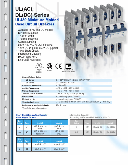
UL(AC),DL(DC) SeriesUL489 Miniature Molded Case Circuit BreakersCurrent/ Voltage RatingUL-Series DL-SeriesCalibration Temperature Ambient Temperature Storage Temperature Terminal Torque (min/max)Electrical Life Mechanical Life Vibration ResistanceResistance to mechanical shocks 0.3 - 63A/ 240V AC, 0.3-32A/ 480Y/277V AC*0.3 - 63A/ 125/ 250V DC 40ºC (104ºF)-25ºC to +55ºC (-13ºF to 131ºF )-40ºC to +70ºC (-40ºF to 158ºF )2 Nm (17.7 lb.in.) / 2.5Nm (22.2 lb.in)6000 switching cycles ON/ OFF 10000 switching cycles ON/ OFF> 15g according to DIN EN 60069-2-59 during a load with I 1= 1.05 x I N 25g @ 11msIEC 60947-2Short Circuit Tested•Available in AC and DC models •DIN Rail Mounted •17.5mm width •Thermal Magnetic •Current Limiting•240V , 480Y/277V AC, 50/60Hz•125V DC (1 pole); 250V DC (2pole)•10kA Short Circuit Interrupting Capacity •HACR Type 40°C •Line/Load reversibleLISTED USE329510C.B.No.Poles Type 0.3-32A 40-63A 1AC 10kA @ 120, 240,10kA @ 120,277V 240V 2-3AC10kA @ 120, 240,10kA @ 120480Y/277V240VNo.Poles Type 0.3-3240-63A 1AC 15kA@240V 15kA@240V 2-3AC15kA@415V10kA@415VNo.Poles Type 0.3-32A 40-63A 1DC 10kA @ 125V 10kA @ 125V 2DC10kA @ 250V10kA @ 250VAltech Corp.®• 35 Royal Road • Flemington, NJ 08822-6000 • Phone (908)806-9400 • FAX (908)806-9490 • *One device dual voltage ratings.Short Circuit Interrupting Capacity According to UL 489Interrupting CapacityAccording to IEC 60947-2, DIN EN 60937-2PENDING8D-Characteristics AC1.05xRC1.35xRC10xRC16xRCD-Characteristics DC1.05xRC1.35xRC14xRC22.4xRC*The value of each characteristic is shown vertically beneath its corresponding heading.Characteristic Trip Boundaries Trip-Characteristics*ApplicationsC-Characteristics ACC-Characteristics DCThermal TripLighting Control CircuitsWiring Protection Business Equipment AppliancesTransformersPower Supplies HeatersMust not Trip>100ms Must Trip <1hr Must not Trip>100ms Must Trip at 100ms Magnetic TripLowInrush High InrushMotorsReactive LoadTelecommu-nications/Computer EquipmentPower Supplies1.05xRC1.35xRC5xRC10xRC1.05xRC1.35xRC7xRC14xRCWarning!This information should only be used as a selection guide. T he use of a Miniature Circuit Breaker in an application with a certain T rip-Characteristic always requires prototype testing! It is the responsibility of the circuit design engineer to select the appropriate Miniature Circuit Breaker for his specific application.1 Pole2 Pole3 Pole17.5 mm 36.5 m m36.8 m m35 mm 52.5 mm68.4 mm51.5 mm30.5 mm51.5 mm37.5 mm25.5 mm14.5 mm45 m m105.3 m m52.5 m m34.5 m m8467Dimensions in mmTrip CharacteristicVoltage Rating Rated Current No. of PolesApproval for heating,refrigerating and air conditioning devices.ApprovalCircuit DiagramShort Circuit RatingProduct SeriesIndividual Part Number is shownMarking DetailsAltech Corp.®• 35 Royal Road • Flemington, NJ 08822-6000 • Phone (908)806-9400 • FAX (908)806-9490 • C -TripCharacteristicLISTED USE329510C.B.Application Examples:Low inrush motors, resistive loads, wiring protection, receptacles,lighting, and control circuit applications. Relatively short thermal trip delay and medium magnetic trip point.Standard Pack: 12Weight:0.3-32A:1.74kg (3.83lb.)40-63A:1.98kg (4.37lb.)Standard Pack: 6Weight:0.3-32A:1.74kg (3.83lb.)40-63A:1.98kg (4.37lb.)Standard Pack: 4Weight:0.3-32A:1.74kg (3.83lb.)40-63A:1.98kg (4.37lb.)Rated Type/ Rated Current Cat. No. Voltage 0.3A 1C03UL 277V AC 0.5A 1C05UL 277V AC 1.0A 1C1UL 277V AC 1.6A 1C1.6UL 277V AC 2.0A 1C2UL 277V AC 3.0A 1C3UL 277V AC 4.0A 1C4UL 277V AC 5.0A 1C5UL 277V AC 6.0A 1C6UL 277V AC 8.0A 1C8UL 277V AC 10A 1C10UL 277V AC 12A 1C12UL 277V AC 13A 1C13UL 277V AC 15A 1C15UL 277V AC 16A 1C16UL 277V AC 20A 1C20UL 277V AC 25A 1C25UL 277V AC 30A 1C30UL 277V AC 32A 1C32UL 277V AC 40A 1C40UL 240V AC 50A 1C50UL 240V AC 60A 1C60UL 240V AC 63A 1C63UL 240V ACOne PoleThree PoleTwo PoleAdd-on Neutral PoleRated Type/ Rated Current Cat. No. Voltage 0.3A 2C03UL 480Y/277V AC 0.5A 2C05UL 480Y/277V AC 1.0A 2C1UL 480Y/277V AC 1.6A 2C1.6UL 480Y/277V AC 2.0A 2C2UL 480Y/277V AC 3.0A 2C3UL 480Y/277V AC 4.0A 2C4UL 480Y/277V AC 5.0A 2C5UL 480Y/277V AC 6.0A 2C6UL 480Y/277V AC 8.0A 2C8UL 480Y/277V AC 10A 2C10UL 480Y/277V AC 12A 2C12UL 480Y/277V AC 13A 2C13UL 480Y/277V AC 15A 2C15UL 480Y/277V AC 16A 2C16UL 480Y/277V AC 20A 2C20UL 480Y/277V AC 25A 2C25UL 480Y/277V AC 30A 2C30UL 480Y/277V AC 32A 2C32UL 480Y/277V AC 40A 2C40UL 240V AC 50A 2C50UL 240V AC 60A 2C60UL 240V AC 63A 2C63UL 240V ACRated Type/ Rated Current Cat. No. Voltage 0.3A 3C03UL 480Y/277V AC 0.5A 3C05UL 480Y/277V AC 1.0A 3C1UL 480Y/277V AC 1.6A 3C1.6UL 480Y/277V AC 2.0A 3C2UL 480Y/277V AC 3.0A 3C3UL 480Y/277V AC 4.0A 3C4UL 480Y/277V AC 5.0A 3C5UL 480Y/277V AC 6.0A 3C6UL 480Y/277V AC 8.0A 3C8UL 480Y/277V AC 10A 3C10UL 480Y/277V AC 12A 3C12UL 480Y/277V AC 13A 3C13UL 480Y/277V AC 15A 3C15UL 480Y/277V AC 16A 3C16UL 480Y/277V AC 20A 3C20UL 480Y/277V AC 25A 3C25UL 480Y/277V AC 30A 3C30UL 480Y/277V AC 32A 3C32UL 480Y/277V AC 40A 3C40UL 240V AC 50A 3C50UL 240V AC 60A 3C60UL 240V AC 63A 3C63UL 240V ACRated Type/ Rated Current Cat. No. Voltage 0.3-32A N32UL 480/277V AC 40-63A N63UL 240V ACStandard Pack: 6Weight:0.99kg (2.18 lb.)Standard Dual Connection Terminal•Box clamp terminals Top: 18-3 AWG;Bottom: 18-2 AWG (Line/Load reversible)•Ring tongue terminalsRing tongueBox clamp*May differ by manufacturer. T op terminal ring tongue max. thickness 1.6mm.18.3 mm (0.72 in.)M5 screw11.3 mm (0.44 in.)m a x . 8-12 m m (0.31-0.47 i n .)5.3 m m (0.21 i n .)UL - Series 10Altech Corp.®• 35 Royal Road • Flemington, NJ 08822-6000 • Phone (908)806-9400 • FAX (908)806-9490 • Application Examples:High inrush motors, transformers, power supplies, heaters and reactive loads. Relatively long thermal trip delay and very high magnetic trip point.LISTED USE329510C.B.Standard Pack: 12Weight:0.3-32A:1.74kg (3.83lb.)40-63A:1.98kg (4.37lb.)Standard Pack: 6Weight:0.3-32A:1.74kg (3.83lb.)40-63A:1.98kg (4.37lb.)Standard Pack: 4Weight:0.3-32A:1.74kg (3.83lb.)40-63A:1.98kg (4.37lb.)Rated Type/ Rated Current Cat. No. Voltage 0.3A 1D03UL 277V AC 0.5A 1D05UL 277V AC 1.0A 1D1UL 277V AC 1.6A 1D1.6UL 277V AC 2.0A 1D2UL 277V AC 3.0A 1D3UL 277V AC 4.0A 1D4UL 277V AC 5.0A 1D5UL 277V AC 6.0A 1D6UL 277V AC 8.0A 1D8UL 277V AC 10A 1D10UL 277V AC 12A 1D12UL 277V AC 13A 1D13UL 277V AC 15A 1D15UL 277V AC 16A 1D16UL 277V AC 20A 1D20UL 277V AC 25A 1D25UL 277V AC 30A 1D30UL 277V AC 32A 1D32UL 277V AC 40A 1D40UL 240V AC 50A 1D50UL 240V AC 60A 1D60UL 240V AC 63A 1D63UL 240V ACOne PoleThree PoleTwo PoleAdd-on Neutral PoleRated Type/ Rated Current Cat. No. Voltage 0.3A 2D 03UL 480Y/277V AC 0.5A 2D 05UL 480Y/277V AC 1.0A 2D 1UL 480Y/277V AC 1.6A 2D 1.6UL 480Y/277V AC 2.0A 2D 2UL 480Y/277V AC 3.0A 2D 3UL 480Y/277V AC 4.0A 2D 4UL 480Y/277V AC 5.0A 2D 5UL 480Y/277V AC 6.0A 2D 6UL 480Y/277V AC 8.0A 2D 8UL 480Y/277V AC 10A 2D 10UL 480Y/277V AC 12A 2D 12UL 480Y/277V AC 13A 2D 13UL 480Y/277V AC 15A 2D 15UL 480Y/277V AC 16A 2D 16UL 480Y/277V AC 20A 2D 20UL 480Y/277V AC 25A 2D 25UL 480Y/277V AC 30A 2D 30UL 480Y/277V AC 32A 2D 32UL 480Y/277V AC 40A 2D 40UL 240V AC 50A 2D 50UL 240V AC 60A 2D 60UL 240V AC 63A 2D 63UL 240V ACRated Type/ Rated Current Cat. No. Voltage 0.3A 3D 03UL 480Y/277V AC 0.5A 3D 05UL 480Y/277V AC 1.0A 3D 1UL 480Y/277V AC 1.6A 3D 1.6UL 480Y/277V AC 2.0A 3D 2UL 480Y/277V AC 3.0A 3D 3UL 480Y/277V AC 4.0A 3D 4UL 480Y/277V AC 5.0A 3D 5UL 480Y/277V AC 6.0A 3D 6UL 480Y/277V AC 8.0A 3D 8UL 480Y/277V AC 10A 3D 10UL 480Y/277V AC 12A 3D 12UL 480Y/277V AC 13A 3D 13UL 480Y/277V AC 15A 3D 15UL 480Y/277V AC 16A 3D 16UL 480Y/277V AC 20A 3D 20UL 480Y/277V AC 25A 3D 25UL 480Y/277V AC 30A 3D 30UL 480Y/277V AC 32A 3D 32UL 480Y/277V AC 40A 3D 40UL 240V AC 50A 3D 50UL 240V AC 60A 3D 60UL 240V AC 63A 3D 63UL 240V ACRated Type/ Rated Current Cat. No. Voltage 0.3-32A N32UL 480/277V AC 40-63A N63UL 240V ACStandard Pack: 6Weight:0.99kg (2.18 lb.)Standard Dual Connection Terminal•Box clamp terminals T op: 18-3 AWG;Bottom: 18-2 AWG (Line/Load reversible)•Ring tongue terminalsRing tongueBox clamp*May differ by manufacturer. T op terminal ring tongue max. thickness 1.6mm.18.3 mm (0.72 in.)M5 screw11.3 mm (0.44 in.)m a x . 8-12 m m (0.31-0.47 i n .)5.3 m m (0.21 i n .)D -TripCharacteristicUL - SeriesC-Trip (DC) Characteristic Application Examples: Telecommunication equipment,computer equipment, uniterruptable power supplies.Standard Pack: 12Weight:0.3-32A:1.86kg (4.1lb.)40-63A:2.10kg (4.6lb.)Standard Pack: 6Weight:0.3-32A:1.86kg (4.1lb.)40-63A:2.10kg (4.6lb.)Rated Type/ RatedCurrent Cat. No. Voltage0.3A1C03DL125V DC0.5A1C05DL125V DC1.0A1C1DL125V DC1.6A1C1.6DL125V DC2.0A1C2DL125V DC3.0A1C3DL125V DC4.0A1C4DL125V DC5.0A1C5DL125V DC6.0A1C6DL125V DC8.0A1C8DL125V DC10A1C10DL125V DC12A1C12DL125V DC13A1C13DL125V DC15A1C15DL125V DC16A1C16DL125V DC20A1C20DL125V DC25A1C25DL125V DC30A1C30DL125V DC32A1C32DL125V DC40A1C40DL125V DC50A1C50DL125V DC60A1C60DL125V DC63A1C63DL125V DCOne Pole Two PoleRated Type/ RatedCurrent Cat. No. Voltage0.3A2C03DL250V DC0.5A2C05DL250V DC1.0A2C1DL250V DC1.6A2C1.6DL250V DC2.0A2C2DL250V DC3.0A2C3DL250V DC4.0A2C4DL250V DC5.0A2C5DL250V DC6.0A2C6DL250V DC8.0A2C8DL250V DC10A2C10DL250V DC12A2C12DL250V DC13A2C13DL250V DC15A2C15DL250V DC16A2C16DL250V DC20A2C20DL250V DC25A2C25DL250V DC30A2C30DL250V DC32A2C32DL250V DC40A2C40DL250V DC50A2C50DL250V DC60A2C60DL250V DC63A2C63DL 250V DC For the latest on Altech Circuit Breakers specifications please visit /breaker.Standard DualConnection Terminal•Box clamp terminalsT op: 18-3 AWG;Bottom: 18-2 AWG(Line/Load reversible)•Ring tongue terminalsRingtongueBoxclamp*May differ by manufacturer. T op terminal ring tongue max. thickness 1.6mm.18.3 mm(0.72 in.)M5 screw11.3 mm(0.44 in.)max.8-12mm(.31-.47in.)5.3mm(.21in.)LISTEDUSE329510C.B.DL - Series++–––+Warning!Correct polarity must be observedwhen connecting the DC circuit breakers.12D-Trip (DC) Characteristic Application Examples: Telecommunication equipment,computer equipment, uniterruptable power supplies.Standard Pack: 12Weight:0.3-32A:1.86kg (4.1lb.)40-63A:2.10kg (4.6lb.)Standard Pack: 6Weight:0.3-32A:1.86kg (4.1lb.)40-63A:2.10kg (4.6lb.)Rated Type/ RatedCurrent Cat. No. Voltage0.3A1D03DL125V DC0.5A1D05DL125V DC1.0A1D1DL125V DC1.6A1D1.6DL125V DC2.0A1D2DL125V DC3.0A1D3DL125V DC4.0A1D4DL125V DC5.0A1D5DL125V DC6.0A1D6DL125V DC8.0A1D8DL125V DC10A1D10DL125V DC12A1D12DL125V DC13A1D13DL125V DC15A1D15DL125V DC16A1D16DL125V DC20A1D20DL125V DC25A1D25DL125V DC30A1D30DL125V DC32A1D32DL125V DC40A1D40DL125V DC50A1D50DL125V DC60A1D60DL125V DC63A1D63DL125V DCOne Pole Two PoleRated Type/ RatedCurrent Cat. No. Voltage0.3A2D03DL250V DC0.5A2D05DL250V DC1.0A2D1DL250V DC1.6A2D1.6DL250V DC2.0A2D2DL250V DC3.0A2D3DL250V DC4.0A2D4DL250V DC5.0A2D5DL250V DC6.0A2D6DL250V DC8.0A2D8DL250V DC10A2D10DL250V DC12A2D12DL250V DC13A2D13DL250V DC15A2D15DL250V DC16A2D16DL250V DC20A2D20DL250V DC25A2D25DL250V DC30A2D30DL250V DC32A2D32DL250V DC40A2D40DL250V DC50A2D50DL250V DC60A2D60DL250V DC63A2D63DL250V DC LISTEDUSE329510C.B.DL - SeriesStandard DualConnection Terminal•Box clamp terminalsTop: 18-3 AWG;Bottom: 18-2 AWG(Line/Load reversible)•Ring tongue terminalsRingtongueBoxclamp*May differ by manufacturer. T op terminal ring tongue max. thickness 1.6mm.18.3 mm(0.72 in.)M5 screw11.3 mm(0.44 in.)max.8-12mm(.31-.47in.)5.3mm(.21in.)++–––+Warning!Correct polarity must be observedwhen connecting the DC circuit breakers.13Altech Corp.®• 35 Royal Road • Flemington, NJ 08822-6000 • Phone (908)806-9400 • FAX (908)806-9490 • Type/ Cat No.DescriptionContacts TypeStd PkH10UL 1 Auxiliary Contact 1NO 6H11UL 2 Auxiliary Contacts 1NO + 1NC 6H12UL 3 Auxiliary Contacts 1NO + 2NC 6H21UL 3 Auxiliary Contacts 2NO + 1NC 6HLS11L*1 Auxiliary/1 Signal Contact 1CO + 1CO (Signal)6Max. Operating Type/ Cat No.Description Current @ Un Std Pk FA12UL 12V AC/DC 1.3A 5FA24UL 24V AC/DC 0.6A 5FA48UL 48 - 72V AC/DC 0.2A50.25A @ 110V FA110UL0.5A @ 240V 50.58A @ 277V110 - 240V AC/DC,277V ACRated Operating 10A@240V AC Currents3A@110V AC 1A@220V AC Minimum Contact Load 1mA @ 24V DC Torquemax. 0.8Nm (7 lb.in)Wire Range :Single Wire 1.0mm² - 2.5mm² (18-14 AWG)Stranded Wire 1.0mm² - 1.5mm² (18-16 AWG)Stranded Wire 1.0mm² - 1.5mm² (18-16 AWG)with FerruleType/ Cat No.Rated Current InRated Voltage Std Pk N32UL 0.3 - 32A 480Y/277V AC 6N63UL40 - 63A240V AC6UL/DL Series AccessoriesAuxiliary Contact, Alarm SwitchShunt TripNeutral Pole8.8 mm63.8 mm6 mm45 m m87 m m 52.7 m m17.7 m m51.5mm 37.5mm25.5mm 52.5m m45m m34.5m m36.5m m36.8m m105.3m m6mm7mm8mm 14.5mm17.5mm30.5mm 51.5mm 68.4mm4mm89.5 m m45 m mc a . 180-20045 m m17.5 mm21.8 mmAWG 236 mm68.4 mm 43.6 mm45 m m88 m m9 mm68.4 mm43.8 mm63.8 mm6 mm12.4 mmLISTED C.B. ACC.3NY7E335632For mounting instructions please refer to page 43.Dimensions HxxUL.Dimensions HLS11L.Dimensions NxxUL, FAxxULDimensions UA120ULType/ Cat No.Line Voltage V E Std PkUA120UL120V AC, 60Hz5Reset-Hold Voltage = 0.85 x V EDrop-Out Voltage = 0.35 ~ 0.7 x V EV E = Rated Voltage* UL PendingUndervoltage Trip*Type/ Cat No.Std Pk E98341910Mounting Screw 34mmto connect the auxiliary contact and shunt trip or neutral Pole to the circuit breaker.Type/ Cat No.Std Pk EASS10Lock-out AdapterType/ Cat No.Std Pk BS.UL100Touch Protection Capsto cover the terminal screw holes on the switching devices, neutral Poles and shunt trips for increased touch protection.14Altech Corp.®• 35 Royal Road • Flemington, NJ 08822-6000 • Phone (908)806-9400 • FAX (908)806-9490 • “C” Magnetic Trip Parameters Rated current 0.3A to 63A.1. Hold for a minimum of 100ms at surge of 5 times rated current.2. Trip in under 100ms at 10 times rated current.“D” Magnetic Trip Parameters Rated current 0.3A to 63A.1. Hold for a minimum of 100ms at surge of 10 times rated current.2. Trip in under 100ms at 16 times rated current.10-34x10-310-24x10-210-10.41410141040601234568102040100Multiple of Rated CurrentS e c o n d sM i n u t e sT r i p p i n g t i m e tThermal Overload“Must T rip” < 1 hr = 135% RC “Must Not Trip” > 1 hr = 105% RC1.05-1.35xI N 0.3A Through 10A Rated Current 10-34x10-310-24x10-210-10.41410141040601234568102040100Multiple of Rated CurrentS e c o n d sM i n u t e sT r i p p i n g t i m e tThermal Overload“Must T rip” < 1 hr = 135% RC “Must Not Trip” > 1 hr = 105% RC1.05-1.35xI N 12A Through 63A Rated Current1.05-1.35xI N1234568102040100Multiple of Rated Current10-34x10-310-24x10-210-10.4141014104060S e c o n d sM i n u t e sT r i p p i n g t i m e t16Thermal Overload“Must T rip” < 1 hr = 135% RC “Must Not T rip” > 1 hr = 105% RC0.3A Through 10A Rated Current10-34x10-310-24x10-210-10.4141014104060123451668102040100Multiple of Rated CurrentS e c o n d sM i n u t e sT r i p p i n g t i m e tThermal Overload“Must T rip” < 1 hr = 135% RC “Must Not T rip” > 1 hr = 105% RC1.05-1.35xI N 12A Through 63A Rated CurrentUL Series (AC) Trip CurvesC (AC) Trip CurveD (AC) Trip Curve10-34x10-310-24x10-210-10.41410141040601234567810142040100Multiple of Rated CurrentS e c o n d sM i n u t e sT r i p p i n g t i m e tThermal Overload“Must Trip” < 1 hr = 135% RC “Must Not T rip” > 1 hr = 105% RC1.05-1.35xI N 0.3A Through 10A Rated Current 1.05-1.35xI N1234578102040100Multiple of Rated Current 10-34x10-310-24x10-210-10.4141014104060S e c o n d sM i n u t e sT r i p p i n g t i m e t14Thermal Overload“Must Trip” < 1 hr = 135% RC “Must Not T rip” > 1 hr = 105% RC12A Through 63A Rated Current 10-34x10-310-24x10-210-10.41410141040601234568101422.440100Multiple of Rated CurrentS e c o n d sM i n u t e sT r i p p i n g t i m e tThermal Overload“Must T rip” < 1 hr = 135% RC “Must Not Trip” > 1 hr = 105% RC1.05-1.35xI N 0.3A Through 10A Rated Current10-34x10-310-24x10-210-10.41410141040601234514681022.440100Multiple of Rated CurrentS e c o n d sM i n u t e sT r i p p i n g t i m e tThermal Overload“Must T rip” < 1 hr = 135% RC “Must Not T rip” > 1 hr = 105% RC1.05-1.35xI N 12A Through 63A Rated CurrentUL Series (DC) Trip CurvesC (DC) Trip CurveD (DC) Trip Curve“C” Magnetic Trip Parameters Rated current 0.3A to 63A.1. Hold for a minimum of 100ms at surge of 7 times rated current.2. Trip in under 100ms at 14 times rated current.“D” Magnetic Trip Parameters Rated current 0.3A to 63A.1. Hold for a minimum of 100ms at surge of 14 times rated current.2. Trip in under 100ms at 22.4 times rated current.16Short Circuit Current I [kA]Time Basis:t=8.3msUL/ DL Series Internal ResistanceUL Series Let-through Energy I 2t Diagram, D Trip 1 poleRated CurrentTrip Characteristic (A)C D (Ohm)(Ohm)0.316.862016.86200.5 6.8540 6.00091.0 1.7000 1.75601.60.58700.58702.00.41900.41903.00.20200.20204.00.10900.10905.00.06540.06546.00.05280.04918.00.02780.0240100.02160.0187120.00840.0085130.00840.008515/ 160.00850.0076200.00670.0064250.00500.004130/ 320.00320.0027400.00250.0022500.00190.001860/ 630.00180.0017For other Trip/Pole configurations use the following correction factors:C T rip 1 pole + 0.84 x curve value C T rip 2 pole + 0.71 x curve value C T rip 3 pole + 0.92 x curve valueD T rip 1 pole + 1.00 x curve value D T rip 2 pole + 0.87 x curve value D T rip 3 pole + 1.08 x curve value。
海康威视DSD2055NL拼接屏技术参数

产品简介
DS-D2055NL液晶显示单元,采用超窄边面板,屏幕之间拼缝仅仅为5.5mm。
超高亮度,500cd/m²,直下式LED背光源,显示单元亮度更加均匀,无边界暗影现象。
工业级设计,使用寿命远高于普通家用液晶显示单元,可长达60000小时。
屏幕内置拼接控制器,可将同源信号实现屏幕的自拼接。
选用的LCD液晶显示单元具有丰富的接口,可接收DVI,VGA, HDMI, YPbPr等各种信号。
支持多种控制方式。
订货型号
DS-D2055NL
功能特性
• 直下式LED背光源,显示单元亮度更加均匀,无边界暗影现象;
• 物理分辨率高达1920*1080;
• 极高的显示分辨率,画面细腻,色彩丰富;
• 高清晰度、高亮度、高色域;
• 视角可达178°,趋近于水平;
• 显示面积大、体积小、重量轻;
• 更长的显示寿命;
• 多种选择拼接方式,能适应各种使用场所;
• 超薄窄边设计;
• 稳定运行寿命超长,维护成本低,可24小时持续工作;
• 智能风扇控温,环保静音;
• 挂架、支架、机柜等多种安装方式供用户选择;
• 金属外壳,防辐射、防磁场、防强电场干扰;
• 工作湿度:10%~85%,在恶劣环境下仍能正常使用。
物理接口
端口特性。
品牌:IVQ Seriesчного标题:固定消防系统中的品牌和产品说明书

Optionale externe Stromversorgung
04.02.21 11:42
Quick Selection Guide Fire Systems: Brandmelderzentrale GLT 500 Serie
Automatische Brandmelder
CTN
Kurzbeschreibung
CTN FNM-320-SRD FNM-320-FRD FNM-320-SWH FNM-320-FWH MSS300-WH-EC FNS-320-SRD FNS-320-SYE FNS-320-SWH FNS-320-SGR FNM-320-LEDSRD
Kurzbeschreibung Akustischer Signalgeber rot, Aufputz-Montage Akustischer Signalgeber rot, Unterputz-Montage Akustischer Signalgeber weiß, Aufputz-Montage Akustischer Signalgeber weiß, Unterputz-Montage Meldersockelsirene weiß Rundumkennleuchte rot, Aufputz-Montage Rundumkennleuchte gelb, Aufputz-Montage Rundumkennleuchte durchsichtig, Aufputz-Montage Rundumkennleuchte grün, Aufputz-Montage Akustischer Signalgeber rot mit LED, Aufputz-Montage
Max. Anzahl/Zone lokale Vorschriften beachten lokale Vorschriften beachten lokale Vorschriften beachten lokale Vorschriften beachten lokale Vorschriften beachten lokale Vorschriften beachten lokale Vorschriften beachten lokale Vorschriften beachten lokale Vorschriften beachten lokale Vorschriften beachten lokale Vorschriften beachten
- 1、下载文档前请自行甄别文档内容的完整性,平台不提供额外的编辑、内容补充、找答案等附加服务。
- 2、"仅部分预览"的文档,不可在线预览部分如存在完整性等问题,可反馈申请退款(可完整预览的文档不适用该条件!)。
- 3、如文档侵犯您的权益,请联系客服反馈,我们会尽快为您处理(人工客服工作时间:9:00-18:30)。
751KD05NX*thru8R0MD05NX*4 to 460 Volts Varistor0.20 to 22.5 JouleFeatures• Radial-Lead Varistor• Designed to be Operated Continuously Across AC Power Lines • No Derating Up to 85к Ambient• Available in Tape and Reel or Bulk PackMaximum Ratings• Operating Ambient Temperature Range: -55к to +85к• Storage Temperature Range: -55к to +125к• Temperature Coefficient (өV) of Clamping Voltage (V C ) at Specified Test Current:<0.05%/к•Varistor voltage temperature coefficient:CURRENT, ENERGY AND POWER DERATING CURVE-551606080100120204060AMBIENT TEMPERATURE (°C)PERCENT OF RATED VALUE14080100120•UL Recognized File # E306895(UL1449) and E306942(UL1414)omp onents 20736 Marilla Street Chatsworth! "# $ % ! "#TMMicro Commercial ComponentsNote : 'X' can be S, C, I or Y .*'S' denotes straight lead'C' denotes out crimped lead 'I' denotes inner crimped lead 'Y' denotes kink lead160x(100/ć)Electrical Characteristics @ 25O C Unless Otherwise Noted*680K-8R0M Max. Clamping Voltage testing current 1AMicro Commercial Components(V)(V)(J)(V)(V)751KD05NX 46061522.5750(675-825)1290681KD05NX 42056021.5680(612-748)1150621KD05NX 38550520.5620(558-682)1050561KD05NX 35046019.5560(504-616)940511KD05NX 32041818.5510(459-561)880471KD05NX 30038517.5470(423-517)810431KD05NX 27535016.5430(387-473)745391KD05NX 25032015.0390(351-429)675361KD05NX 23030013.0360(324-396)620331KD05NX 21027511.5330(297-363)575301KD05NX 19525010.5300(270-330)525271KD05NX 1752259.9270(243-297)475241KD05NX 1502008.4240(216-264)415221KD05NX 1401807.8220(198-242)380201KD05NX 1301707.1200(185-225)355181KD05NX 115150 6.5180(162-198)320151KD05NX 95125 5.5150(135-165)260121KD05NX 75100 4.0120(108-132)210101KD05NX 6085 3.5100(90-110)175820KD05NX 5065 2.882(74-90)145680KD05NX 4056 2.168(61-75)*150560KD05NX 3545 1.856(50-62)*123470KD05NX 3038 1.547(42-52)*104390KD05NX 2531 1.239(35-43)*86330KD05NX 2026 1.133(30-36)*73270KD05NX 17220.927(24-30)*60220KD05NX 14180.722(20-24)*48180LD05NX 11140.618(15-21)*40120MD05NX 680.312(9.6-14.4)*338R0MD05NX45.50.28(6.4-9.6)*242000.1V5A (A)50250.01100500.01400Rated WattageVaristor VoltageMaximum Clamping VoltageACrms DC 10/1000us1 time2 times(W)V1mA Part NumberMaximum AllowableVoltageMaximum EnergyWithstanding SurgeCurrent9070698420758060504030400300200150100AV-I Curve (180L to 680K)V70504030AV-I Curve (820K to 471K)V908060Micro Commercial Components0.11001100010100V-I Surge Life Time Ratings (180L to 680K)AµsImpulse Current – Amperes Impulse Width – Micro seconds0.324300.20.40.5352040500.1110100V-I Surge Life Time Ratings (820K to751K)AµsImpulse Current – Amperes Impulse Width – Micro seconds30020010000400Micro Commercial ComponentsNote 2.T Thickness (max.)Unit:mmMicro Commercial ComponentsPart CodeD05D07D10D14D20182K 12.612.813.5112K 10.510.711.2102K 9.910.110.7911K 9.49.610.1821K 8.38.89.09.5781K 8.18.68.89.3751K 7.97.98.48.69.1681K 7.57.58.08.28.7621K 7.27.27.67.88.3561K 6.9 6.97.37.58.0511K 6.6 6.67.07.27.7471K 6.4 6.4 6.87.07.5431K 6.1 6.1 6.5 6.77.2391K 5.3 5.3 5.7 5.9 6.4361K 5.1 5.1 5.5 5.7 6.2331K 4.9 4.9 5.3 5.5 6.0301K 4.8 4.8 5.2 5.4 5.9271K 4.6 4.6 5.0 5.2 5.7241K 4.4 4.4 4.8 5.0 5.5221K 4.3 4.3 4.7 4.9 5.4201K 4.2 4.2 4.6 4.8 5.3181K 4.1 4.1 4.5 4.7 5.2151K 4.5 4.5 4.9 5.1 5.6121K 4.1 4.1 4.5 4.6 5.3101K 3.9 3.9 4.4 4.5 5.1820K 3.8 3.8 4.3 4.4 4.9680K 5.5 5.5 6.0 6.1 6.1560K 5.0 5.0 5.5 5.6 5.6470K 5.0 5.0 5.5 5.6 5.6390K 4.7 4.7 5.1 5.2 5.4330K 4.7 4.7 5.1 5.2 5.4270K 4.7 4.7 5.1 5.2 5.4220K 4.5 4.5 4.9 5.0 5.3180L4.54.54.95.05.2Micro Commercial Components***IMPORTANT NOTICE***Micro Commercial Components Corp.reserve s the right to make changes without further notice to any product herein to make corrections, modifications , enhancements , improvements , or other changes .Micro Commercial Components Corp.does not assume any liability arising out of the application or use of any product described herein; neither does it convey any license under its patent rights ,northe rights of others . The user of products in such applications shall assume all risks of such use and will agree to hold Micro Commercial Components Corp.and all the companies whoseproducts are represented on our website, harmless against all damages.***APPLICATIONS DISCLAIMER***Products offer by Micro Commercial Components Corp.are not intended for use in Medical,Aerospace or Military Applications.。