TMS320DSP算法标准_XDAIS_及参考构架RF5综述
RF5

框架参考框架。
RF5适用于含有多通道和多算法结构的高密集度应用程序。
与低等级参考框使用线程(任务TSK)阻塞,可用于包含线程间有复杂依赖关系的应用程序。
另还具有可变的通道管理、基于任务TSK的应用程序、高效的任务间通信,以及结构化的线程安全控制机制,且易于替换I/O驱动设备和易于调试。
参考框架最重要的要求就是保证易于与用户硬件接口。
每一个参考架构均被打包成基于开发工具包或其他板卡的完整的应用程序。
针对每一个板卡,可以提供不同等级的参考框架。
对应用软件进行调整以适合参考框架,主要有3个基本要求:调整算法单元和改变通道数量;调整应用程序以使其适应硬件系统;改变驱动以利于运行终端硬件。
了一个通道基础框架,使其很容易就可以封装XDAIS算法。
通过这一封装,应用程序设计1.1RF5数据处理RF5共有4个基本的数据处理部件:任务(task)、通道(channel)、单元(cell)和标准算法(XDAIS algorithm)。
它们之间的关系如图3所示。
通常,一个任务中可以包括一个或多个通道,每个通道中可以包括一个或多个单元,而每个单元中则封装有一个XDAIS算法。
单元封装XDAIS算法的作用在于:提供算法与外部世界的一个标准接口,每个单元执行一个简单的ICELL接口,通过该接口执行算法。
利用通道可以按序执行多个单元,在典型应用中,多个通道可能包含一套执行功能相同的单元序列。
利用任务可以同时处理一个或多个通道,其目的在于组织任务间的数据通信和设备驱动会话等。
与通道不同的是,任务有具体的执行代码,并需要用户自己编写。
该部分代码通常是从外界接收数据、控制通道执行等。
每个任务总是反复执行自己的代码,完成检查控制信息、获得数据、执行通道、发送数据等操作。
1.2RF5中数据通信RF5中的数据通信包括task级通信和cell级通信。
其通信机理为使用结构体进行信息传递,而非通过全局变量传输处理数据。
1.2.1t ask级通信任务级通信主要用到了SCOM消息队列和邮箱(MBX)。
第四章 TMS320系列DSP芯片

A23~0 D31~0
定时器 0 定时器 1 串口0 串口1
8 扩展精度寄存器 8 辅助寄存器 2 变址寄存器 地址产生 1 地址产生 2 12 控制寄存器
TMS320C30的功能结构图
大连理工大学出版社
4.2
4.2.2
1
位
0 1
TMS320C3x系列 DSP
寄存器 状态寄存器
寄存器与存储器
名称
C V
大连理工大学出版社
4.1
4.1.2
1
TMS320C2xx系列 DSP
TMS320F206引脚与兼容性
TMS320F206 的引脚
A12~A15 A8~A11 A7 A4~A6 A0~A3
71~74 O/Z 66~69 64 60~62 55~58 ... ...
地址线,对片外的数据空间、I/O空 间访问时,F206驱动地址线, OFF= 0时为高阻。
大连理工大学出版社
4.1
4.1.1
TMS320C2xx系列 DSP
TMS320F206的结构特点
7) 程序空间和数据空间之间可进行数据搬移; 8) 8级内部硬件堆栈,存放调用/中断返回地址; 9) 片内设备: 16bit定时器;片上软等待产生器:可以分别为PS、DS、 IS空间产生0~7个等待;片上振荡器和锁相环,有倍频和分频 功能:乘1、乘2、乘4、除2;6个通用I/O引脚;全双工异步串 口UART;增强的同步串口,带4级FIFO。 10) 硬件等待; 11) 休眠的IDLE模式,低功耗; 12) 标准的IEEE1149.1仿真口; 13) 100脚表贴器件。
大连理工大学出版社
4.1
4.1.3
1
位 15~13
2、TMS320系列DSP的介绍
OMAP OMAP5910
TM
C5441 532 MIPS C5421 200 MIPS C5420 200 MIPS C5470
C54xTM+ARM7
C54xTM DSP
World’s Most Popular DSP Over 500 Million Shipped $5 Billion in Design-ins
C5407 120 MIPS
Feature Integration
TI所推进的开放式多媒体应用平台 所推进的开放式多媒体应用平台
Open Multimedia Application Platform 处理器
Applications Processor Integrated Baseband and Applications Processor
TV 因特网 浏览器 无线 AP
?
高集成度的OMAP5910提供单片系统功能 提供单片系统功能 高集成度的
OMAP5910 Core TMS320C55xTM DSP
DSP
32 16
3 Timers Watchdog Timer Interrupt Handler 2 McBSP 2MCSI 3 UART 18 GPIO 4 Mailboxes
TMS320C6000DSP的应用
同一应用的多通道复用
蜂窝基站 复用的调制解调器 中央办公交换机 多信道线路回声抵消 多信道话音编码器 Head end cable modem 中央办公XDSL
TMS320C6000DSP的应用(续)
视频图象的压缩、处理、传输
远程监控(PSTN/ISDN/ADSL) 网络视频终端 数码摄像机
Traffic Ctrl 75 MHz
TMS320C55x的DSP概括

DSP原理与应用大作业姓名:潘俊涛班级:应电121班学号:1204141192014年6月第1部分概述一、DSP简介;当德州仪器(TI)公司在1982年研发出第一款商用数字信号处理器是,谁也不会想到它竟能给世界带来如此大的变化。
从移动通信到消费电子领域,从汽的第一代数字信号处理器仅包含了55000个晶体管,4KB内存处理指令只有5MIPS (每秒百万条),经过二十余年的发展,单核数字信号处理器的处理能力已经达到9600MIPS的惊人速度,寻址能力高达1280MB。
而第三代数字信号处理器则以其强大的数字信号处理能力、超低功耗和适合手持设备的超小型封装的等特点,较好的满足了新一代电子产品的要求。
二、DSP的发展;20世纪60年代以来,随着信息技术的不断进步,数字信号处理系统也应运而生并得到迅速的发展。
80年代以前,由于方法的限制,数字信号处理技术处于理论研究阶段,还得不到广泛的应用。
在此阶段,人们利用通用计算机进行数字滤波、频谱分析等算法的研究,以及数字信号处理系统的模拟和仿真。
实施数字信号处理对数字信号处理系统的处理能力提出了严格的要求,所有运算、处理都必须小于系统可接受的最大时延。
典型的数字信号处理系统的基本部分:抗混叠滤波器、模/数转换器、数字信号处理、数/模转换器和抗镜像滤波器。
以下几种问为当前实用的数字信号处理系统:1、利用X86处理器完成实时数字信号处理2、利用通用微处理器成实时数字信号处理3、利用可编程逻辑阵列(FPGA)进行成实时数字信号处理4、利用数字信号处理器(DSP)实现数字信号处理三、DSP的特点;DSP系统的应用领域极其广泛,目前主要的应用领域如下:基本信号处理、通信、语音、图形图像、军事、仪器仪表、控制、医疗和家用电器。
DSP最大的应用领域是通信,并且军事领域是高性能DSP的天地。
众所周知,微处理器的存储结构分为两大类:冯.诺伊曼结构和哈弗结构。
DSP广泛使用冯.诺伊曼结构。
TMS320 DSP

Application ReportSPRA577B Using the TMS320 DSP Algorithm Standard in aStatic DSP System Carl Bergman Digital Signal Processing Solutions AbstractThe TMS320 DSP Algorithm Standard is part of TI's eXpressDSP (XDAIS) technologyinitiative. It allows system designers to easily integrate algorithms from a variety ofsources (e.g., third parties, customers). However, in system design, flexibility comes witha price.This price is paid in CPU cycles and memory space, both critical in all DSP systems, but perhaps most critical in a static system. For this application note, a static system isdefined as one in which memory is allocated once and is used for the remainder of thesystem's life – there is no effort to reclaim or reuse memory. In contrast, a dynamicsystem is one in which the memory is reused while the application is executing. Adynamic system takes advantage of the available memory by sharing it betweenalgorithms, by reclaiming it when an algorithm is deactivated, and by reusing it whenanother algorithm is activated.Algorithms that comply with the TMS320 DSP Algorithm Standard are tested andawarded an eXpressDSP compliant mark upon successful completion of the test. Thisapplication note shows how an eXpressDSP-compliant algorithm may be used effectively in a static system with limited memory. It examines some optimizations and illustratesthem with a very simple example: an algorithm that copies input to output. The impact interms of code size, data size, and CPU cycles will be demonstrated.ContentsTheory of Operation (3)Review of TMS320 DSP Algorithm Standard Fundamentals (3)Naming Conventions (3)Interface Function Summary (4)Sequence of Builds (6)Build 1: No eXpressDSP Interface – Access Algorithm Directly (6)Build 2: Using the High Level Interface, 'CPY' (8)Build 3: Using and Removing Subsections in the Linker Command File (10)Build 4: Removing the Code from the CPY High-Level Interface (12)Build 5: Using Only the SPI – Creating the Object at Design Time (12)Conclusion (13)References (14)TI Contact Numbers (15)FiguresFigure 1.Test Program (6)Figure 2.Build 1 Code Size (8)Figure ing the TMS320 Algorithm Standard Interface (9)Figure 4.Build 2 Code Size (10)Figure 5.Define Subsections (11)Figure 6.NOLOAD Section in Linker Command File (11)Figure 7.Build 3 Code Size (11)Theory of OperationThe TMS320 DSP Algorithm Standard provides a general-purpose interface that allowsefficient use of a large variety of algorithms in a large variety of systems. However, thefull capability of the interface may not be useful in all systems. In a static system wemight allocate memory at design-time and initialize the algorithm at power-on and neverchange anything else. In such a system, the code implementing the create and deletefunctions, although never used, would take up valuable memory.This application note follows an example program through a sequence of steps aimed at reducing code size by linking only the required functions. The unused code is assigned toa subsection that will not be loaded by the linker. The steps in the examples involveincrementally more programming effort. The result is that the code is smaller and lessmemory is used.We begin with a typical implementation of the interface and then illustrate the processwith several optimizations. The first build provides a baseline for comparison. It calls the algorithm directly with no algorithm standard interface. The second build adds the fullalgorithm standard interface. The remaining examples simplify the use of the interfaceand recover the memory from the unused functions.Review of TMS320 DSP Algorithm Standard Fundamentals Some of the key structures of an eXpressDSP-compliant algorithm are:X Memory Table: Describes what memory the algorithm needs in order to operateX Creation Parameters: Describes how the algorithm should be initializedX Status Information: Describes the current state of the algorithmX Function Table: Describes the operations available for the algorithmThere are two levels of access to the algorithm:1) The service provider interface (SPI) provides the most direct access.2) The application programmer's interface (API) provides an alternate, more convenientinterface.The high-level functions of the API use the SPI to create and control the algorithm and to process data.Naming ConventionsThe TMS320 Algorithm Standard naming convention ensures that implementations of the same algorithm from different vendors can co-exist without duplicate symbols. This ismade possible by defining a two-part prefix to external symbols. Part one of the prefixrepresents the algorithm and part two represents the vendor.In our example, the symbol for the 'copy' algorithm is the mnemonic 'CPY'. The symbol for the vendor “Texas Instruments” is the acronym 'TI'. This yields the prefix 'CPY_TI_'.An example of a function name using this prefix would be CPY_TI_create(). This name indicates that TI implements the create function for the copy algorithm.An example of an interface name would be 'CPY_TI_ICPY'. This name indicates that TI implements the interface to the copy algorithm (ICPY) for the copy algorithm. This maysound redundant, but there are other possible interfaces to the copy algorithm. Forexample, the test interface (ITST) in this example would be named 'CPY_TI_ITST'. Interface Function SummaryThe functions that implement the two levels of access (API and SPI) may be organizedaccording to whether they apply to all algorithms (generic), apply to a specific algorithm (algorithm-specific), or apply to a specific implementation of an algorithm (vendor-specific). The naming convention helps here as well. The generic create function would be ALG_create(). The algorithm-specific create function would be CPY_create() with the copy algorithm mnemonic as a prefix. The vendor-specific function (if TI was the vendor) would have the name CPY_TI_create().Functions beginning with 'CPY_' (Algorithm Specific API)The algorithm-specific API is the most convenient access to the algorithm and is asuperset of the TMS320 algorithm standard API.CPY_activate()Prepare the algorithm to runCPY_control()Command and status mechanismCPY_create()Allocate memory and initialize a new algorithm instanceCPY_deactivate()Prepare the algorithm to be inactive or possibly deletedCPY_delete()Remove algorithm instance and deallocate the memory usedCPY_exit()Finalize module other than deleting algorithm instanceCPY_init()Initialize module other than creating algorithm instanceCPY_process()Process dataFunctions Beginning With 'ALG_' (Standard API)The following do not include the algorithm-specific processing function calls.ALG_activate()Prepare the algorithm to runALG_control()Command and status mechanismALG_create()Allocate memory and initializes a new algorithm instanceALG_deactivate()Prepare the algorithm to be inactive or possibly deletedALG_delete()Remove algorithm instance and deallocate the memory usedALG_exit()Finalize module other than deleting algorithm instanceALG_init()Initialize module other than creating algorithm instanceThe CPY_IALG Interface (Standard SPI)The IALG interface functions are described in the comments field of the ialg.h file./** ======== IALG_Fxns ========* This structure defines the fields and methods that must be supplied by* all XDAIS algorithms.** implementationId - unique pointer that identifies the module* implementing this interface.* algActivate() - notification to the algorithm that its memory* is "active" and algorithm processing methods* may be called. May be NULL; NULL => do nothing.* algAlloc() - apps call this to query the algorithm about* its memory requirements. Must be non-NULL.* algControl() - algorithm specific control operations. May be* NULL; NULL => no operations supported.* algDeactivate() - notfication that current instance is about to* be "deactivated". May be NULL; NULL => do nothing. * algFree() - query algorithm for memory to free when removing* an instance. Must be non-NULL.* algInit() - apps call this to allow the algorithm to* initialize memory requested via algAlloc(). Must* be non-NULL.* algMoved() - apps call this whenever an algorithms object or* any pointer parameters are moved in real-time.* May be NULL; NULL => object can not be moved.* algNumAlloc() - query algorithm for number of memory requests.* May be NULL; NULL => number of mem recs is less* then IALG_DEFMEMRECS.*/The CPY_ICPY Interface (Standard SPI Plus Algorithm Extensions) The algorithm extensions provide the data processing function.cpyProcess()Copy data from input buffer to output bufferThe CPY_TI_ICPY Interface (Standard SPI Plus Algorithm Extensions Plus Vendor's Extensions)The copy algorithm has no vendor extensions.Sequence of BuildsBuild 1: No eXpressDSP Interface – Access Algorithm Directly The first build is for comparison purposes. The test program accesses the algorithmdirectly. The copy algorithm only needs the count field in the object and the input andoutput data buffers. Note that the eXpressDSP header files are included to support theuse of the ICPY_TI_Obj structure, which is expected by the algorithm. Figure 1 showsthe code from main() of the test program.The system resources used are measured in terms of code size and CPU cycles. Thecode size is shown in the excerpt from the linker map file in Figure 2. The CPU cycles for the data processing function are determined with the profiler in Code Composer Studio[1].Program Memory Used37,408 bytesData Memory Used4,480 bytesCPU Cycles Used20441 (average of 3 runs on a C6201 EVM card)Figure 1.Test Program/** build1.c*/#include <stdio.h> // access to printf()#include <std.h> // basic data types#include <xdais.h> // XDAIS data types#include <ialg.h> // IALG standard#include <icpy.h> // ICPY standard#include <icpy_ti.h> // ICPY implementation#include <copydata.h> // algorithm implementation/* test data */#define COPY_COUNT 16#define BUFFER_SIZE 80Char * testString = "eXpress DSP Algorithm Standard";Char buffer[BUFFER_SIZE];Int main(){ICPY_TI_Handle handle;ICPY_TI_Obj cpyObj;Char *cp, *input, *output;Int i;printf("build1 1999 0802 1036\n");/* init test buffers ---------------------------------------- */input = testString;output = buffer;/* clear output buffer */cp = output;for (i = BUFFER_SIZE; i > 0; i--) {*cp++ = (Char)0;}printf("input: %s\n", input);printf("output: %s\n", output);/* init the algorithm ---------------------------------------*/handle = (ICPY_TI_Handle)&cpyObj;/* if create failed then exit (can't happen but keep consistent) */ if (handle == NULL) {printf ("object creation failed\n");exit(1);}else {printf ("object created\n");}/* use the algorithm ----------------------------------------*//* set the count of bytes to copy */printf ("cpyControl\n"); // for fair code comparisonprintf ("ICPY_SET_COPY_COUNT\n"); // for fair code comparisoncpyObj.count = 5;i = 1; // place profile point here/* do the copy operation */printf ("cpyProcess\n"); // for fair code comparisoncopyData(handle, input, output);i = 0; // place profile point here/* report results ------------------------------------------- */printf("copy %d bytes, output: %s\n", cpyObj.count, output);printf("end of build1\n");/* for fair code size comparison: from the control function */ printf ("ICPY_READ_STATUS\n");printf ("ICPY_WRITE_STATUS\n");printf ("default case!\n");return(0);}Figure 2.Build 1 Code SizeMEMORY CONFIGURATIONname origin length used attributes fill-------- -------- --------- -------- ---------- -------- PMEM 00000000 000010000 00000000 RWIXEXT0 00400000 000040000 00000000 RWIXEXT1 01400000 000300000 00000000 RWIXEXT2 02000000 000400000 00009220 RWIXEXT3 03000000 000400000 00000000 RWIXDMEM 80000000 000010000 00001180 RWIXSECTION ALLOCATION MAPsection page origin length input sections-------- ---- ---------- ---------- ----------------.text 0 02000000 00008500.cinit 0 02008500 00000414.cio 0 02008914 00000120 UNINITIALIZED.far 0 02008a34 000007ec UNINITIALIZED.stack 0 80000000 00000800 UNINITIALIZED.bss 0 80000800 00000054 UNINITIALIZED.const 0 80000854 0000012c.sysmem 0 80000980 00000800 UNINITIALIZEDBuild 2: Using the High Level Interface, 'CPY'The second build represents a baseline of using the copy algorithm in a static systemwith an algorithm standard interface.The code is built using Code Composer Studio (CCStudio) with the followingcomponents:Build2.mak Code Composer Studio Project FileBuild2.c Test Programmem.c Memory Allocation Utilitycpy.c Algorithm Specific High Level Interfacealg.c Standard High Level Interfacecpy.lib Algorithm LibraryBuild2.cmd Linker Command FileSystem resources used:Build 1Build 2ChangeProgram Memory (bytes)37408404563048Data Memory (bytes)44804615135CPU Cycles2044121343902The code in Figure 3 is an excerpt from the function main() in build2.c and shows thefollowing steps:1) Using the high level CPY API, an instance of the algorithm is created.2) The copy count is then changed from the default value with a control call and thecopy process is run on the input and output buffers.3) Finally, a control call is made to retrieve status, which in our case simply proves wecan find out what the copy count was.Figure ing the TMS320 Algorithm Standard Interface/* init the algorithm --------------------------------------- *//* create an instance of the algorithm object */handle = CPY_create(&CPY_ICPY, ¶mDefaults);/* if create failed then exit */if (handle == NULL) {printf ("object creation failed\n");exit(1);}else {printf ("object created\n");}/* use the algorithm ---------------------------------------- *//* set the count of bytes to copy */CPY_control(handle, ICPY_SET_COPY_COUNT, (Void *)5);i = 1;/* place profile point here *//* do the copy operation */CPY_process(handle, input, output);i = 0;/* place profile point here *//* read back the copy count */CPY_control(handle, ICPY_READ_STATUS, &status);Figure 4 is an excerpt from the Build 2 linker map file.Figure 4.Build 2 Code SizeMEMORY CONFIGURATIONname origin length used attributes fill-------- -------- --------- -------- ---------- -------- PMEM 00000000 000010000 00000000 RWIXEXT0 00400000 000040000 00000000 RWIXEXT1 01400000 000300000 00000000 RWIXEXT2 02000000 000400000 00009e08 RWIXEXT3 03000000 000400000 00000000 RWIXDMEM 80000000 000010000 00001207 RWIXSECTION ALLOCATION MAPsection page origin length input sections-------- ---- ---------- ---------- ----------------.text 0 02000000 00009080.cinit 0 02009080 0000047c.cio 0 020094fc 00000120 UNINITIALIZED.far 0 0200961c 000007ec UNINITIALIZED.stack 0 80000000 00000800 UNINITIALIZED.bss 0 80000800 0000008c UNINITIALIZED.const 0 8000088c 0000017b.sysmem 0 80000a08 00000800 UNINITIALIZEDBuild 3: Using and Removing Subsections in the Linker Command FileIn the next build, the code is the same as Build 2 (refer to Figure 3). We now addpragma directives to all the interface levels to assign an input subsection for eachfunction statement (see Figure 5). This allows us to selectively include or exclude the subsections in the link process.System resources used:Build 1Build 3ChangeProgram Memory (bytes)37408394322024Data Memory (bytes)44804615135CPU Cycles2044121132691Figure 5.Define Subsections#pragma CODE_SECTION(CPY_activate, ".text:algActivate")#pragma CODE_SECTION(CPY_apply, ".text:algApply")#pragma CODE_SECTION(CPY_control, ".text:algControl")#pragma CODE_SECTION(CPY_create, ".text:algCreate")#pragma CODE_SECTION(CPY_deactivate, ".text:algDeactivate")#pragma CODE_SECTION(CPY_delete, ".text:algDelete")#pragma CODE_SECTION(CPY_exit, ".text:algExit")#pragma CODE_SECTION(CPY_init, ".text:algInit")Subsections are selected in the linker command file. By specifying a NOLOAD outputsection, the unused code is removed from the program image (see Figure 6). The code is built the same way as in Build 2.Figure 6.NOLOAD Section in Linker Command FileSECTIONS{....notUsed {* (.text:algActivate)* (.text:algApply)* (.text:algDeactivate)* (.text:algDelete)* (.text:algExit)* (.text:algInit)* (.text:algMoved)* (.text:algNumAlloc)} type = NOLOAD >EXT3...}Figure 7 is an excerpt from the Build 3 linker map file.Figure 7.Build 3 Code SizeMEMORY CONFIGURATIONname origin length used attributes fill-------- -------- --------- -------- ---------- -------- PMEM 00000000 000010000 00000000 RWIXEXT0 00400000 000040000 00000000 RWIXEXT1 01400000 000300000 00000000 RWIXEXT2 02000000 000400000 00009a08 RWIXEXT3 03000000 000400000 00000400 RWIXDMEM 80000000 000010000 00001207 RWIXSECTION ALLOCATION MAPsection page origin length input sections-------- ---- ---------- ---------- ----------------.text 0 02000000 00008c80.cinit 0 02008c80 0000047c.cio 0 020090fc 00000120 UNINITIALIZED.far 0 0200921c 000007ec UNINITIALIZED.stack 0 80000000 00000800 UNINITIALIZED.bss 0 80000800 0000008c UNINITIALIZED.const 0 8000088c 0000017b.sysmem 0 80000a08 00000800 UNINITIALIZED.notUsed 0 03000000 00000400 NOLOAD SECTIONBuild 4: Removing the Code from the CPY High-Level InterfaceIn the fourth build, we replace the calls to the CPY interface (CPY_* functions) withmacros that call the standard API (ALG_* functions) and the SPI. The three macrosshown replace the corresponding function calls to CPY_control(), CPY_create() andCPY_process().#define CPY_CONTROL(alg, cmd, status) \((alg->fxns->ialg.algControl)((IALG_Handle)alg, cmd, status));#define CPY_CREATE(fxns, prms) \(CPY_Handle)ALG_create((IALG_Fxns *)fxns, (IALG_Params *)prms);#define CPY_PROCESS(alg, input, output) \(alg->fxns->cpyProcess)((ICPY_Handle)alg, input, output);This allows us to eliminate the file cpy.c from our build. The rest remains the same.System resources used:Build 1Build 4ChangeProgram Memory (bytes)37408392241816Data Memory (bytes)44804611131CPU Cycles2044120725284Build 5: Using Only the SPI – Creating the Object at Design TimeIn Build 5, we remove the remaining API code in alg.c from the program. We can do this because we are going to 'create' the object and declare the data structures the algorithm requires at design time in the test program. Four steps are required for this build:1) Allocate the space for the memory descriptor table.memTab =(IALG_MemRec *)malloc(sizeof(memTab[IALG_DEFMEMRECS]));2) Plug in the addresses of our allocated object and working memory to the memorydescriptor table.memTab[CPY_OBJ_DATA].base =(void *)malloc(sizeof(ICPY_TI_Obj));memTab[CPY_DATA_RAM].base =(void *)malloc(sizeof(cpyDataRam));3) Set the value of our handle to the algorithm. We also set the address of the functiontable in the object. Previously ALG_create() set the function table address andreturned the value of our handle.handle = (CPY_Handle)memTab[CPY_OBJ_DATA].base;handle->fxns = &CPY_ICPY;4) Initialize the algorithm. For this, we call the SPI directly with the parameters itexpects. If the initialization fails, the handle is set to NULL.if (handle->fxns->ialg.algInit((IALG_Handle)handle, memTab,NULL, (IALG_Params *)¶mDefaults) != IALG_EOK) {handle = NULL;}Now with alg.c and mem.c removed from the program (memory allocation is no longerused) and with the subsection .text:algAlloc placed in the .notUsed section, we build theprogram as before.System resources used:Build 1Build 5ChangeProgram Memory (bytes)3740838232824Data Memory (bytes)44804611131CPU Cycles2044120653212ConclusionThese build techniques allowed us to reduce the program memory overhead for using the algorithm standard from 3048 bytes to 824 bytes, a 70% reduction. This wasaccomplished by using only the service provider interface (SPI) and by placing unusedcode in a NOLOAD section.Build 1Build 2Build 3Build 4Build 5Program Memory3740840456394323922438232Change304820241816824Percent of XDAIS100.00%66.40%59.58%27.03%The data memory was not really affected, with a change of only 4 bytes from Build 3 toBuild 4.Build 1Build 2Build 3Build 4Build 5Data Memory44804615461546114611Change From Build 1135135131131The CPU cycle count for the data processing call was measured with the profiler in Code Composer Studio. Because our copy algorithm has only 160 bytes of code, it is important to note that the percentage of overhead of the algorithm standard interface in a morerealistic algorithm would be much smaller than what is shown.With that in mind, the most direct use of the SPI gives us a cycle count of 212 – a littlemore than 1% of the total cycles used in the data processing call. This is less than 24%of the 902 cycles used with the full algorithm standard interface in Build 2.Build 1Build 2Build 3Build 4Build 5CPU Cycles2044121343211322072520653Change902691284212Percent of Total 4.41% 3.38% 1.39% 1.04%In an actual case with a G.723 algorithm, the processing call takes an average of375,000 cycles, and the overhead of 212 cycles would be less than 0.1%. The overhead of the full interface at 902 cycles would be less than 0.25%.Finally, the following chart summarizes the improvements in program memory for the examples given.eXpressDSP Overhead On Program Memory1000200030004000Build 2Build 3Build 4Build 5B y t e s References1.Code Composer Studio User's Guide , SPRU328.2.TMS320C6000 Assembly Language Tools User's Guide , SPRU186.3.TMS320 DSP Algorithm Standard Rules and Guidelines , SPRU352.4. TMS320 DSP Algorithm Standard API Reference, SPRU360.TI Contact NumbersINTERNETTI Semiconductor Home Page/scTI Distributors/sc/docs/distmenu.htm PRODUCT INFORMATION CENTERS AmericasPhone+1(972) 644-5580Fax +1(972) 480-7800Email sc-infomaster@ Europe, Middle East, and Africa PhoneDeutsch+49-(0) 8161 80 3311 English+44-(0) 1604 66 3399 Español+34-(0) 90 23 54 0 28 Francais+33-(0) 1-30 70 11 64 Italiano+33-(0) 1-30 70 11 67 Fax+44-(0) 1604 66 33 34 Email epic@JapanPhoneInternational+81-3-3344-5311 Domestic0120-81-0026FaxInternational+81-3-3344-5317 Domestic0120-81-0036Email pic-japan@ AsiaPhoneInternational+886-2-23786800 DomesticAustralia1-800-881-011TI Number-800-800-1450China10810TI Number-800-800-1450Hong Kong800-96-1111TI Number-800-800-1450India000-117TI Number-800-800-1450Indonesia001-801-10TI Number-800-800-1450Korea080-551-2804Malaysia1-800-800-011TI Number-800-800-1450New Zealand000-911TI Number-800-800-1450Philippines105-11TI Number-800-800-1450Singapore800-0111-111TI Number-800-800-1450Taiwan080-006800Thailand0019-991-1111TI Number-800-800-1450Fax886-2-2378-6808Email tiasia@TI is a trademark of Texas Instruments Incorporated.Other brands and names are the property of their respective owners.IMPORTANT NOTICETexas Instruments and its subsidiaries (TI) reserve the right to make changes to their products or to discontinue any product or service without notice, and advise customers to obtain the latest version of relevant information to verify, before placing orders, that information being relied on is current and complete. All products are sold subject to the terms and conditions of sale supplied at the time of order acknowledgment, including those pertaining to warranty, patent infringement, and limitation of liability.TI warrants performance of its semiconductor products to the specifications applicable at the time of sale in accordance with TI’s standard warranty. Testing and other quality control techniques are utilized to the extent TI deems necessary to support this warranty. Specific testing of all parameters of each device is not necessarily performed, except those mandated by government requirements.Customers are responsible for their applications using TI components.In order to minimize risks associated with the customer’s applications, adequate design and operating safeguards must be provided by the customer to minimize inherent or procedural hazards.TI assumes no liability for applications assistance or customer product design. TI does not warrant or represent that any license, either express or implied, is granted under any patent right, copyright, mask work right, or other intellectual property right of TI covering or relating to any combination, machine, or process in which such semiconductor products or services might be or are used. TI’s publication of information regarding any third party’s products or services does not constitute TI’s approval, warranty or endorsement thereof.Copyright © 2000, Texas Instruments Incorporated。
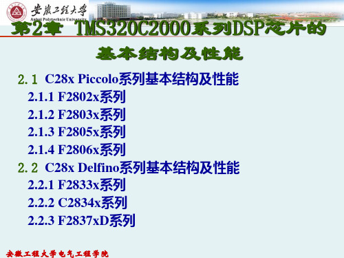
第2章 TMS320C2000系列DSP芯片的基本结构及性能
安徽工程大学电气工程学院
安徽工程大学电气工程学院
2.1 C28x Piccolo系列基本结构及性能
2008年10月,TI发布了基于C2000 DSP的 Piccolo系列,取自意大利语“风笛”,是以小巧、 低成本、高集成度为主要特点的32位微控制器,采 用最新的架构技术成果和增强型外设,能够提供一 款低成本的高集成度解决方案,有助于在成本敏感 型应用中实现处理器密集型的32位实时控制功能。 Piccolo系列可提供多种封装版本和外设选项,实现 了高性能、高集成度、小尺寸以及低成本的完美组 合。
安徽工程大学电气工程学院
2.1.1 F2802x系列
F2802x Piccolo系列为C28x内核供电,此内核与低引脚数 量器件中的高集成控制外设相耦合。该系列的代码与以往基于 C28x的代码相兼容,并且提供了很高的模拟集成度。 F2802x 系列速度为40-60MHz,配有多达64KB Flash,属于低成本入 门级产品。
•
安徽工程大学电气工程学院
2.2.1 F2833x系列
F2833x系列速度为100-150MHz,Flash多达 512KB。它们是针对要求严格的控制应用的高度集成、 高性能解决方案。
安徽工程大学电气工程学院
2.2.2 C2834x系列
C2834x系列性能翻倍,达到300MHz,但是此系 列解决方案仅限于基于RAM的存储,RAM可达到 516KB。
安徽工程大学电气工程学院
C2000是一种注重实时控制应用的微控制器系列,应用 范围包括数字电源、数字电机控制、位置传感、汽车雷达等。
C2000器件核心是一个32位C28x CPU,其频率范围介于40400MHz之间,外加浮点单元,部分器件还配有控制律加速 器(CLA),它实际上成为与CPU并行运行的第二个内核, 能够独立地控制外设。 目前在TMS320C2000系列产品中,TI主要推出了四个系 列主流产品,即使用广泛的C28x定点系列、低成本与高创新 的C28x Piccolo系列、C28x Delfino浮点性能系列以及基于 C28x和ARM Cortex-M3的Concerto多核系列。图2-1给出了
DSP——TMS320C数字图像处理方案

目录摘要 (I)Abstract (II)1绪论 (1)1.1图像处理的研究背景 (1)1.2图像处理国内外研究现状 (2)1.3 图像处理研究内容及意义 (4)1.3.1图像处理研究内容 (4)1.3.2本文的研究意义 (5)1.4 小结 (6)2 基于DSP的开发系统 (7)2.1 DSP系统简介 (7)2.2 DSP芯片 (7)2.2.1 DSP芯片的基本结构 (8)2.2.2 DSP芯片的种类 (8)2.2.3世界主要的DSP芯片制造公司及其产品 (9)2.2.4 DSP发展现状及应用简介 (10)2.2.5 DSP技术展望 (12)2.3 DSP芯片的特点 (12)2.4图像处理中DSP芯片的选择 (15)2.5基于DSP的图像处理系统 (16)3 CCS开发环境的应用与仿真 (17)3.1 CCS的安裝及简介 (17)3.1.1 CCS简介 (17)3.1.2 CCS的安装使用 (19)3.1.3 CCS的配置与使用 (21)3.2仿真处理分析 (22)4基于DSP的图像处理 (24)4.1图像处理的基本概念 (24)4.2图像处理的硬件系统 (24)4.2.1 TMS320C6000 DSP芯片的硬件系统 (24)4.2.2 TMS320C6000的硬件结构简介 (26)4.2.3试验平台评估 (28)4.3基于DSP的图像处理实现 (29)4.3.1图像直方图统计 (29)4.3.2数字图像边缘检测sobel 算子 (30)4.3.3数字图像锐化laplace 算子 (32)4.3.4图像取反 (35)4.3.5数字图像直方图均衡化增强 (36)4.4试验及结果分析 (37)结论 (42)致谢 (43)参考文献 (44)附录 (45)1绪论1.1图像处理的研究背景数字图像处理又称为计算机图像处理在国外最早出现于20世纪50年代,当时的电子计算机已经发展到一定水平,人们开始利用计算机来处理图形和图像信息。
2.DSP学习进阶

DSP学习进阶学习TI的各种DSP,本着循序渐进的原则,可以分为多个层次在这里总结一下各个层次的进阶:1、DSP2000(除了2812):进阶:标准C -> C和汇编混合编程说明:把DSP2000当作单片机来玩就可以了,非常简单。
2、DSP5000(包括DSP2812)主要:标准C -> C和汇编混合编程-> DSP/BIOS -> RF3说明:DSP5000是个中等产品,性能不高不低,基本上也没有开发难度。
3、DSP6000主要:标准C -> C和汇编混合编程-> DSP/BIOS -> XDAIS -> RF5 说明:DSP6000的开发难度明显增大,不论是硬件还是软件。
还分为两种档次:(1)DSP62XX & DSP67XX:开发这两类DSP,硬件上会初步遇到信号完整性问题,软件方面来说,DSP/BIOS是必需的,复杂的程序还需要XDAIS和RF3、RF5的知识。
(2)DSP64XX:开发难度比较大,硬件方面需要重点考虑系统合理架构问题,信号完整性问题;软件方面,需要综合运用各种比较先进、专业的知识,例如用DSP/BIOS作为RTOS,用RF5作为程序架构,尽量采用MiniDriver来编写底层驱动程序等。
如果深入编程,还会遇到令人困惑的Cache冲突问题(虽然TI最近专门针对这个难题升级了CCS),等等。
另外还有一些辅助知识,根据自己需要可以选学:1、GEL:推荐所有阶段的开发者都要学;2、RTDX:一般来说没有必要学习;3、CCS中的C++面向对象编程技术:不建议采用;4、CSL:对于DSP6000以上的开发,必须的;5、各种DSP库函数:对于复杂算法程序,建议学习。
- 1、下载文档前请自行甄别文档内容的完整性,平台不提供额外的编辑、内容补充、找答案等附加服务。
- 2、"仅部分预览"的文档,不可在线预览部分如存在完整性等问题,可反馈申请退款(可完整预览的文档不适用该条件!)。
- 3、如文档侵犯您的权益,请联系客服反馈,我们会尽快为您处理(人工客服工作时间:9:00-18:30)。
TMS320DSP 算法标准(XDAIS)及参考构架RF5综述司 群1) 臧英新1) 陶友传1) 罗 丹2)(武汉数字工程研究所1) 武汉 430074) (武汉昊昱微电子有限公司2) 武汉 430074)摘 要:主要介绍了TMS320DSP 算法标准和TMS320DSP 算法参考架构RF 。
作为eXpressDSP 软件关键组件的算法参考架构RF 和TMS320数字信号处理器算法标准(XDAIS)定义了一系列编程准则和建议,标准化了算法和系统软件的接口,使得算法使用者的系统集成任务大为减轻,产品开发周期相应大为缩短。
关键词:RF5;XDAIS;eXpressDSP 中图分类号:TP31TMS 320DSP Algorithm Standard and the ReferenceFrameworks Level 5for TMS 320DSPSi Qun 1) Zang Yingxin 1) Tao Youchuan 1) Luo Dan 2)(Wuhan Digital En g ineering Institute 1),Wuhan 430074)(Wuhan Haoyu Micro Electronic Co.Ltd 2).,Wuhan 430074)Abstract:The paper mainly in troduces two key components of the eXpressDSP:the reference frameworks 5for TMS320DSP and the TMS320DSP algorith m standard.With a family of rules and guidelines,they decrease dramatically system integration pressure,shorten sys tem R&D period.Key words:RF5,XDAIS,eXpressDSP Class number:TP311 引言今天,DSP 的应用开发已发生了很大的改变。
图1 eXpressDSP 软件及开发工具硬件技术的发展使得DSP 在保持兼容性的同时使得性能不断提高,功耗不断下降,片上集成度大幅增加;DSP 应用复杂度也在大幅提高,原先几百行的汇编软件程序已被几十万行甚至百万行的C 程序替代;市场的压力要求新产品的开发周期越来越短。
使得软件已成为DSP 方案中最为重要的一环,一个项目的成败也往往由软件实现的好坏决定。
作为业界领先的数字信号处理器供应商,TI 提出了eXpressD SP 的概念来应对DSP 软件的挑战。
e Xpress DSP 软件及开发工具见图1。
TI 还提出了推出27总第152期2006年第2期 舰船电子工程Ship Electronic EngineeringVol.26No.2收稿日期:2005年9月6日,修回日期:2005年9月26日了一系列DSP软件参考框架(RF)并提供有相关支持,帮助DSP应用设计人员加速软件开发进程。
本文主要介绍TMS320DSP算法标准以及DSP 软件参考框架RF5。
2TMS320DSP算法标准(XDAIS)随着数字信号处理器(DSP)的应用范围不断扩大,对面向组件的软件模块的需求不断增长,第三方提供的现成算法在基本层面上能够适应需求。
第三方算法在DSP系统开发中发挥着非常重要的作用。
DSP厂商建立了管理不同算法与应用之间接口的算法标准。
如TMS320系列DSP,称之为TMS320DSP算法标准。
2.1算法标准的起源20世纪90年代中期,算法标准的需求逐渐显现出来,出现了功能更为强大的DSP,可支持一个算法的多通道,或者同一DSP上的多个算法。
如基于TMS320C6000平台的DSP,能够开发DSL线卡、视频服务器及其他在单个设备上要求具有极高多通道性能的系统。
利用现有更高层次的性能,许多新兴信号处理标准不断涌现,包括JPE G、MPEG、电视会议、无线电话以及调制解调器与传真改进等。
开发商开始创建交互改变任务的动态系统,而不是一般基于DSP的具有固定功能的静态系统。
系统代码规模也开始剧增,以适应新型多功能系统的复杂性。
一些DSP开发商开始作为第三方出售其知识产权,包括算法。
系统集成商将从第三方购买黑盒子!目标代码,并将其加载至系统中,以节省宝贵的开发时间。
但是第三方开发商常常假定DSP用法,以便使其算法尽可能精简,并获得最佳性能效果。
而系统集成商可能无法了解开发商的事先假定是什么。
如果有了上述假定的话,那么两种或多种算法就不能在多功能系统中和平共处。
这样的问题在利用源代码进行再设计时可能相当困难,如果算法来自不同的第三方(事实常常如此),集成商将面临不兼容性难题以及不可避免的相互指责。
到20世纪90年代末,DSP厂商开始发布行为规则,将其编写为第三方软件开发商必须遵循的标准代码,以便保证算法的兼容性。
2.2XDAIS算法规则XDAIS规则分四组,具备基本的校验机制以保证符合标准。
常识性编程规则。
本组规则的作用在于加强算法的便携性、可预测性及易用性。
取消任意选择。
该标准指定了应在各种不同方法中采用何种方法(就好像交通法规指定了在路上应左行还是右行)。
对C6000(TM)平台而言,算法必须至少支持由小到大的字节顺序,或最好两个都支持,以便为系统开发商提供选择。
资源管理。
本组位于该标准的核心。
本规则适用于外部及内部存储器,以及DMA通道等外设。
统一规范。
本组规则有助于系统集成商衡量算法并评估其在系统中的兼容性。
所有的兼容性算法必须表现最坏情况的中断传输时间、典型与最坏情况的执行,以及程序、堆阵、静态和堆栈存储器要求等方面的特点。
2.3XDAI S的发展XDAIS在5年前推出时,其规则还不到30条。
现在它已有了46条规则,这反映出对标准的需求不断发展。
新规则的添加(以及一些改动)出于以下几点原因:新硬件功能。
添加某些规则是为了涵盖硅技术的开发。
未来,XDAI S还可能包括有关硬件加速器作为共享资源使用的规则。
性能优化。
为优化性能,DMA规则已进行了修订,在此,这些规则也展示了XDAIS标准中的另一个变化领域。
由于早期规则解决了重大冲突,因此一些较新的指导方针倾向于帮助开发商更好地发挥系统优势。
新应用领域。
XDAIS的最初指导方针主要是为了处理带有数据流应用的单功能DSP,如语音及音视频等。
但今天的多功能系统常常必须处理突发数据,这些应用的核心和系统要求有时与流应用的不同,而XDAIS规则必须包括两种类型的数据吞吐量。
有一个没有改变的特性,即需要将开销保持在较低水平。
经验显示,DSP客户与第三方将接受不超过一至两个百分点的性能及存储器干扰。
这对于通用微处理器而言是一个较小的开销百分比。
但是,通常每个性能MIP对DSP都是非常关键的,因此TI已努力将XDAI S开销保持在限定范围内。
2.4XDAI S的算法接口所有符合XDAIS标准的算法必须实现一个标准接口,I ALG接口。
IALG接口提供的功能有:对系统存储资源的管理,算法实例的建立,初始化和终止对象。
IALG接口提供了一个I ALG_Fxns的结28司 群等:TMS320DSP算法标准(XDAIS)及参考构架RF5综述 总第152期构,又称V表,在这个结构中,除了algAlloc(),al gInit()和algFree()是必须的外,其它的函数都是可选的。
algAlloc()实现存储管理;algInit()用来初始化算法实例对象;algFree()在销毁算法实例对象后,释放存储空间。
除了I ALG,XDAIS还要定义一个算法实例接口,该接口包含了算法的实现。
该接口是算法接口的一个实例。
例如:I G723E NC接口,这是Ti的I TU G.723.1编码器接口,即算法接口。
IG723ENC Fxns扩展了I ALG Fxns,如下所示:typedef struct IG723ENC Fxns{IALG Fxns ialg;/*IG723ENC extend s IALG*/XDAS Bool(*con trol)}(IG723E NC Handle handle; IG723C md cmd,IG723E NC Status*s tatus);XDAS Bool(*encode)(IG723ENC Handle handle, XDAS UInt16*in,XDAS UIn t16*out);}IG723ENC Fxns;在这个结构中除了包含IALG Fxns以外,还定义了control()和encode()两个函数。
这两个函数才是与特定算法相关的函数。
大多数情况下,这个接口对实现算法的函数进行了封装。
对于同一算法,因为有不同的实现,对不同的实现都有不同的算法实例对象,为了便于区分而且不会引起名字冲突,通常以<module><vendor>!来命名算法接口的实例。
<module>为算法名,<vendor>是实现厂商或个人所特有的标示符,如:G723E NC TI I G723E NC,即为TI公司的对G723ENC算法的实现。
我们可以把G723E NC TI IG723E NC看作是IG723E NC的一个实例。
如下:#define IALGFXNS \&G723ENC TI IALG, /*module ID*/ \NULL, /*activate*/ \G723ENC TI algAlloc, /*alloc*/ \NULL, /*control*/ \NULL, /*deactivate*/ \G723ENC TI algFree, /*free*/ \G723ENC TI algInit, /**init*/ \NULL, /*moved*/ \NULL /*numAlloc*/ \IG723ENC Fxns G723E NC TI IG723ENC={IALGFXNS, /*IALG functions*/G723ENC TI control,g723E NC TI encode}G723E NC T I IG723ENC;asm(!G723ENC TI IALG.set G723ENC TI IG723ENC!);第一部分是对IALG的初始化并将它包含进G723E NC TI I G723E NC中,然后把G723ENC TI control和G723ENC TI encode两个函数包含进来,就组成了G723E NC TI I G723E NC结构。
G723E NC TI control和G723ENC TI encode这两个函数是算法的实现函数。