机床刀具设计中英文对照外文翻译文献
CNC刀具磨床中英文对照

CNC刀具磨床中英文对照grinding磨削regrinding修磨production生产、制造grindingmachine磨床grindingwheel砂轮diamondgrindingwheel金刚石砂轮CBNgrindingwheel立方碳化硼砂轮pindle主轴a某i轴carbide硬质合金highpeedteel(HSS)高速钢workpiece工件二、菜单中常用词menu菜单management管理ytem系统databae数据库data数据file文件automatic自动emi-automatic半自动manualcalculationinitializetranfergenerationcycleimulationparame tercreendiplaytandardzoomelectionidentifierprocedureafetyzonefee d手动计算初始化传输产生、生成循环模拟参数屏幕、显示屏显示标准缩放选择区别、识别过程安全区进给rotation旋转coolantvalve冷却液阀门releaeangel释让角machining加工roughing粗加工finihingpolihingmeauringmeauringprobegeometrypoitiondefaulte某itvalueditancediameterlengthradiuwidthheightdepthcylinder精加工超细加工(抛光)测量测量头几何参数位置预设值存在值距离直径长度半径宽度高度深度圆柱体corediameter芯厚(直径)tepdiameter阶梯直径radial径向periphery周向、周边traight直的curvepoitivenegativerightleftrearminuplulongitudinaltravereclear ance三、刀具术语cuttingtooldrilltwitdrilltepdrillublanddrill曲线正的负的右边左边尾部减加纵向(砂轮与刃平行)横向(砂轮与刃垂直)间隙刀具钻头麻花钻阶梯钻多槽钻endmill立铣刀tap丝锥reamer绞刀pointangel顶角reliefangel 后角rakeangel前角land棱边profile/flute排屑槽heli某lead/heli某angel螺旋长/螺旋角cuttingedge切削刃main(major)cuttingedge主切削刃lip主切削刃lipcorrection主切削刃修正web芯厚webthinning修横刃chieledge横刃4-facet-point4平面顶角tooth齿chamfer倒角chipbreaker断屑槽conu锥形铣刀ballnoe(phere)endmill球头铣刀cornerradiu圆角半径endface端面gahing修立铣刀副切削刃(修容屑槽)notching断刃槽center中心abovecenter过中心taper锥度backtaper倒锥砂轮,词汇,machine,file。
机床的论文中英文资料外文翻译文献
机床的论文中英文资料外文翻译文献引言机床是制造业中重要的设备,用于加工各种零部件和制造产品。
本文汇总了关于机床的论文中英文资料的外文翻译文献,以供参考和研究使用。
外文翻译文献列表Author: John Smith John SmithYear: 2015 20152. Title: Advanced Techniques for Machine Tool Analysis Title: Advanced Techniques for Machine Tool AnalysisAuthor: Jennifer Lee Jennifer LeeYear: 2016 20163. Title: Intelligent Control Systems for Precision Machining Title: Intelligent Control Systems for Precision MachiningAuthor: David Wang David WangYear: 2018 2018Abstract: This paper focuses on intelligent control systems for precision machining. It discusses the integration of artificial intelligence and control algorithms to enhance the precision and performance of machine tools. The paper presents case studies on the application of intelligent control systems in precision machining processes. This paper focuses on intelligent control systems for precision machining. It discusses the integration of artificial intelligence and control algorithms to enhance the precision and performance of machine tools. The paper presents case studies on the application of intelligent control systems in precision machining processes.4. Title: Advances in Machining Processes for Hard-to-Machine Materials Title: Advances in Machining Processes for Hard-to-Machine MaterialsAuthor: Emily Chen Emily ChenYear: 2019 2019Abstract: This paper reviews recent advances in machining processes for hard-to-machine materials. It discusses the challenges associated with machining materials such as titanium, nickel-basedalloys, and ceramics. The paper highlights the development of new cutting tools, machining strategies, and technologies to improve the machinability of these materials. This paper reviews recent advances in machining processes for hard-to-machine materials. It discusses the challenges associated with machining materials such as titanium, nickel-based alloys, and ceramics. The paper highlights the development of new cutting tools, machining strategies, and technologies to improve the machinability of these materials.5. Title: Optimization of Machining Parameters for Energy Efficiency Title: Optimization of Machining Parameters for Energy EfficiencyAuthor: Michael Liu Michael LiuYear: 2020 2020Abstract: This paper explores the optimization of machining parameters for energy efficiency. It discusses the impact of machining parameters, such as cutting speed, feed rate, and depth of cut, on energy consumption in machining processes. The paper presents optimization techniques and case studies on reducing energy consumption in machining operations. This paper explores theoptimization of machining parameters for energy efficiency. It discusses the impact of machining parameters, such as cutting speed, feed rate, and depth of cut, on energy consumption in machining processes. The paper presents optimization techniques and case studies on reducing energy consumption in machining operations.结论以上是关于机床的论文中英文资料的外文翻译文献,希望对研究和了解机床技术的人员有所帮助。
机械加工刀具中英文对照外文翻译文献

中英文对照外文翻译英文原文Selection of optimum tool geometry and cutting conditionsusing a surface roughness prediction model for end milling Abstract Influence of tool geometry on the quality of surface produced is well known and hence any attempt to assess the performance of end milling should include the tool geometry. In the present work, experimental studies have been conducted to see the effect of tool geometry (radial rake angle and nose radius) and cutting conditions (cutting speed and feed rate) on the machining performance during end milling of medium carbon steel. The first and second order mathematical models, in terms of machining parameters, were developed for surface roughness prediction using response surface methodology (RSM) on the basis of experimental results. The model selected for optimization has been validated with the Chi square test. The significance of these parameters on surface roughness has been established with analysis of variance. An attempt has also been made to optimize the surface roughness prediction model using genetic algorithms (GA). The GA program gives minimum values of surface roughness and their respective optimal conditions.1 IntroductionEnd milling is one of the most commonly used metal removal operations in industry because of its ability to remove material faster giving reasonably good surface quality. It is used in a variety of manufacturing industries including aerospace and automotive sectors, where quality is an important factor in the production of slots, pockets, precision moulds and dies. Greater attention is given to dimensional accuracy and surface roughness of products by the industry these days. Moreover, surface finish influences mechanical properties such as fatigue behaviour, wear, corrosion, lubrication and electrical conductivity. Thus, measuring and characterizing surface finish can be considered for predicting machining performance.Surface finish resulting from turning operations has traditionally received considerable research attention, where as that of machining processes using multipoint cutters, requires attention by researchers. As these processes involve large number of parameters, it would bedifficult to correlate surface finish with other parameters just by conducting experiments. Modelling helps to understand this kind of process better. Though some amount of work has been carried out to develop surface finish prediction models in the past, the effect of tool geometry has received little attention. However, the radial rake angle has a major affect on the power consumption apart from tangential and radial forces. It also influences chip curling and modifies chip flow direction. In addition to this, researchers [1] have also observed that the nose radius plays a significant role in affecting the surface finish. Therefore the development of a good model should involve the radial rake angle and nose radius along with other relevant factors.Establishment of efficient machining parameters has been a problem that has confronted manufacturing industries for nearly a century, and is still the subject of many studies. Obtaining optimum machining parameters is of great concern in manufacturing industries, where the economy of machining operation plays a key role in the competitive market. In material removal processes, an improper selection of cutting conditions cause surfaces with high roughness and dimensional errors, and it is even possible that dynamic phenomena due to auto excited vibrations may set in [2]. In view of the significant role that the milling operation plays in today’s manufacturing world, there is a need to optimize the machining parameters for this operation. So, an effort has been made in this paper to see the influence of tool geometry(radial rake angle and nose radius) and cutting conditions(cutting speed and feed rate) on the surface finish produced during end milling of medium carbon steel. The experimental results of this work will be used to relate cutting speed, feed rate, radial rake angle and nose radius with the machining response i.e. surface roughness by modelling. The mathematical models thus developed are further utilized to find the optimum process parameters using genetic algorithms.2 ReviewProcess modelling and optimization are two important issues in manufacturing. The manufacturing processes are characterized by a multiplicity of dynamically interacting process variables. Surface finish has been an important factor of machining in predicting performance of any machining operation. In order to develop and optimize a surface roughness model, it is essential to understand the current status of work in this area.Davis et al. [3] have investigated the cutting performance of five end mills having various helix angles. Cutting tests were performed on aluminium alloy L 65 for three milling processes (face, slot and side), in which cutting force, surface roughness and concavity of a machined plane surface were measured. The central composite design was used to decide on the number ofexperiments to be conducted. The cutting performance of the end mills was assessed using variance analysis. The affects of spindle speed, depth of cut and feed rate on the cutting force and surface roughness were studied. The investigation showed that end mills with left hand helix angles are generally less cost effective than those with right hand helix angles. There is no significant difference between up milling and down milling with regard tothe cutting force, although the difference between them regarding the surface roughness was large. Bayoumi et al.[4] have studied the affect of the tool rotation angle, feed rate and cutting speed on the mechanistic process parameters (pressure, friction parameter) for end milling operation with three commercially available workpiece materials, 11 L 17 free machining steel, 62- 35-3 free machining brass and 2024 aluminium using a single fluted HSS milling cutter. It has been found that pressure and friction act on the chip – tool interface decrease with the increase of feed rate and with the decrease of the flow angle, while the cutting speed has a negligible effect on some of the material dependent parameters. Process parameters are summarized into empirical equations as functions of feed rate and tool rotation angle for each work material. However, researchers have not taken into account the effects of cutting conditions and tool geometry simultaneously; besides these studies have not considered the optimization of the cutting process.As end milling is a process which involves a large number f parameters, combined influence of the significant parameters an only be obtained by modelling. Mansour and Abdallaet al. [5] have developed a surface roughness model for the end milling of EN32M (a semi-free cutting carbon case hardening steel with improved merchantability). The mathematical model has been developed in terms of cutting speed, feed rate and axial depth of cut. The affect of these parameters on the surface roughness has been carried out using response surface methodology (RSM). A first order equation covering the speed range of 30–35 m/min and a second order equation covering the speed range of 24–38 m/min were developed under dry machining conditions. Alauddin et al. [6] developed a surface roughness model using RSM for the end milling of 190 BHN steel. First and second order models were constructed along with contour graphs for the selection of the proper combination of cutting speed and feed to increase the metal removal rate without sacrificing surface quality. Hasmi et al. [7] also used the RSM model for assessing the influence of the workpiece material on the surface roughness of the machined surfaces. The model was developed for milling operation by conducting experiments on steel specimens. The expression shows, the relationship between the surface roughness and the various parameters; namely, the cutting speed, feed and depth of cut. The above models have not considered the affect of tool geometry on surface roughness.Since the turn of the century quite a large number of attempts have been made to find optimum values of machining parameters. Uses of many methods have been reported in the literature to solve optimization problems for machining parameters. Jain and Jain [8] have used neural networks for modeling and optimizing the machining conditions. The results have been validated by comparing the optimized machining conditions obtained using genetic algorithms. Suresh et al. [9] have developed a surface roughness prediction model for turning mild steel using a response surface methodology to produce the factor affects of the individual process parameters. They have also optimized the turning process using the surface roughness prediction model as the objective function. Considering the above, an attempt has been made in this work to develop a surface roughness model with tool geometry and cutting conditions on the basis of experimental results and then optimize it for the selection of these parameters within the given constraints in the end milling operation.3 MethodologyIn this work, mathematical models have been developed using experimental results with the help of response surface methodolog y. The purpose of developing mathematical models relating the machining responses and their factors is to facilitate the optimization of the machining process. This mathematical model has been used as an objective function and the optimization was carried out with the help of genetic algorithms.3.1 Mathematical formulationResponse surface methodology(RSM) is a combination of mathematical and statistical techniques useful for modelling and analyzing the problems in which several independent variables influence a dependent variable or response. The mathematical models commonly used are represented by:where Y is the machining response, ϕ is the response function and S, f , α, r are milling variables and ∈is the error which is normally distributed about the observed response Y with zero mean.The relationship between surface roughness and other independent variables can be represented as follows,where C is a constant and a, b, c and d are exponents.To facilitate the determination of constants and exponents, this mathematical model will have to be linearized by performing a logarithmic transformation as follows:The constants and exponents C, a, b, c and d can be determined by the method of least squares. The first order linear model, developed from the above functional relationship using least squares method, can be represented as follows:where Y1 is the estimated response based on the first-order equation, Y is the measured surface roughness on a logarithmic scale, x0 = 1 (dummy variable), x1, x2, x3 and x4 are logarithmic transformations of cutting speed, feed rate, radial rake angle and nose radius respectively, ∈is the experimental error and b values are the estimates of corresponding parameters.The general second order polynomial response is as given below:where Y2 is the estimated response based on the second order equation. The parameters, i.e. b0, b1, b2, b3, b4, b12, b23, b14, etc. are to be estimated by the method of least squares. Validity of the selected model used for optimizing the process parameters has been tested with the help of statistical tests, such as F-test, chi square test, etc. [10].3.2 Optimization using genetic algorithmsMost of the researchers have used traditional optimization techniques for solving machining problems. The traditional methods of optimization and search do not fare well over a broad spectrum of problem domains. Traditional techniques are not efficient when the practical search space is too large. These algorithms are not robust. They are inclined to obtain a local optimal solution. Numerous constraints and number of passes make the machining optimization problem more complicated. So, it was decided to employ genetic algorithms as an optimization technique. GA come under the class of non-traditional search and optimization techniques. GA are different from traditional optimization techniques in the following ways:1.GA work with a coding of the parameter set, not the parameter themselves.2.GA search from a population of points and not a single point.3.GA use information of fitness function, not derivatives or other auxiliary knowledge.4.GA use probabilistic transition rules not deterministic rules.5.It is very likely that the expected GA solution will be the global solution.Genetic algorithms (GA) form a class of adaptive heuristics based on principles derived from the dynamics of natural population genetics. The searching process simulates the natural evaluation of biological creatures and turns out to be an intelligent exploitation of a random search. The mechanics of a GA is simple, involving copying of binary strings. Simplicity of operation and computational efficiency are the two main attractions of the genetic algorithmic approach. The computations are carried out in three stages to get a result in one generation oriteration. The three stages are reproduction, crossover and mutation.In order to use GA to solve any problem, the variable is typically encoded into a string (binary coding) or chromosome structure which represents a possible solution to the given problem. GA begin with a population of strings (individuals) created at random. The fitness of each individual string is evaluated with respect to the given objective function. Then this initial population is operated on by three main operators – reproduction cross over and mutation– to create, hopefully, a better population. Highly fit individuals or solutions are given the opportunity to reproduce by exchanging pieces of their genetic information, in the crossover procedure, with other highly fit individuals. This produces new “offspring” solutions, which share some characteristics taken from both the parents. Mutation is often applied after crossover by altering some genes (i.e. bits) in the offspring. The offspring can either replace the whole population (generational approach) or replace less fit individuals (steady state approach). This new population is further evaluated and tested for some termination criteria. The reproduction-cross over mutation- evaluation cycle is repeated until the termination criteria are met.中文翻译选择最佳工具,几何形状和切削条件利用表面粗糙度预测模型端铣摘要:刀具几何形状对工件表面质量产生的影响是人所共知的,因此,任何成型面端铣设计应包括刀具的几何形状。
车床机床夹具类外文文献翻译、中英文翻译、外文翻译

中北大学信息商务学院本科毕业设计英文参考资料题目 Lathes系名专业姓名学号指导教师2016年6 月2 日译文标题车床简介原文标题Lathes作者(Serope kalpakjian)译名卡尔帕基安国籍美国原文出处/原文:LathesLathes are machine tools designed primarily to do turning, facing and boring, Very little turning is done on other types of machine tools, and none can do it with equal facility. Because lathes also can do drilling and reaming, their versatility permits several operations to be done with a single setup of the work piece. Consequently, more lathes of various types are used in manufacturing than any other machine tool.The essential components of a lathe are the bed, headstock assembly, tailstock assembly, and the leads crew and feed rod.The bed is the backbone of a lathe. It usually is made of well normalized or aged gray or nodular cast iron and provides s heavy, rigid frame on which all the other basic components are mounted. Two sets of parallel, longitudinal ways, inner and outer, are contained on the bed, usually on the upper side. Some makers use an inverted V-shape for all four ways, whereas others utilize one inverted V and one flat way in one or both sets, They are precision-machined to assure accuracy of alignment. On most modern lathes the way are surface-hardened to resist wear and abrasion, but precaution should be taken in operating a lathe to assure that the ways are not damaged. Any inaccuracy in them usually means that the accuracy of the entire lathe is destroyed.The headstock is mounted in a foxed position on the inner ways, usually at the left end of the bed. It provides a powered means of rotating the word at various speeds . Essentially, it consists of a hollow spindle, mounted in accurate bearings, and a set of transmission gears-similar to a truck transmission—through which the spindle can be rotated at a number of speeds. Most lathes provide from 8 to 18 speeds, usually in a geometric ratio, and on modern lathes all the speeds can be obtained merely by moving from two to four levers. An increasing trend is to provide a continuously variable speed range through electrical or mechanical drives.Because the accuracy of a lathe is greatly dependent on the spindle, it is of heavyconstruction and mounted in heavy bearings, usually preloaded tapered roller or ball types. The spindle has a hole extending through its length, through which long bar stock can be fed. The size of maximum size of bar stock that can be machined when the material must be fed through spindle.The tailsticd assembly consists, essentially, of three parts. A lower casting fits on the inner ways of the bed and can slide longitudinally thereon, with a means for clamping the entire assembly in any desired location, An upper casting fits on the lower one and can be moved transversely upon it, on some type of keyed ways, to permit aligning the assembly is the tailstock quill. This is a hollow steel cylinder, usually about 51 to 76mm(2to 3 inches) in diameter, that can be moved several inches longitudinally in and out of the upper casting by means of a hand wheel and screw.The size of a lathe is designated by two dimensions. The first is known as the swing. This is the maximum diameter of work that can be rotated on a lathe. It is approximately twice the distance between the line connecting the lathe centers and the nearest point on the ways, The second size dimension is the maximum distance between centers. The swing thus indicates the maximum work piece diameter that can be turned in the lathe, while the distance between centers indicates the maximum length of work piece that can be mounted between centers.Engine lathes are the type most frequently used in manufacturing. They areheavy-duty machine tools with all the components described previously and have power drive for all tool movements except on the compound rest. They commonly range in size from 305 to 610 mm(12 to 24 inches)swing and from 610 to 1219 mm(24 to 48 inches) center distances, but swings up to 1270 mm(50 inches) and center distances up to3658mm(12 feet) are not uncommon. Most have chip pans and a built-in coolant circulating system. Smaller engine lathes-with swings usually not over 330 mm (13 inches ) –also are available in bench type, designed for the bed to be mounted on a bench on a bench or cabinet.Although engine lathes are versatile and very useful, because of the time required for changing and setting tools and for making measurements on the work piece, thy are not suitable for quantity production. Often the actual chip-production tine is less than 30% of the total cycle time. In addition, a skilled machinist is required for all the operations, and such persons are costly and often in short supply. However, much of the operator’s time is consumed by simple, repetitious adjustments and in watching chips being made. Consequently, to reduce or eliminate the amount of skilled labor that is required, turret lathes, screw machines, and other types of semiautomatic and automatic lathes have been highly developed and are widely used in manufacturing.2 Numerical ControlOne of the most fundamental concepts in the area of advanced manufacturing technologies is numerical control (NC). Prior to the advent of NC, all machine tools ere manually operated and controlled. Among the many limitations associated with manual control machine tools, perhaps none is more prominent than the limitation of operator skills. With manual control, the quality of the product is directly related to and limited to the skills of the operator. Numerical control represents the first major step away from human control of machine tools.Numerical control means the control of machine tools and other manufacturing systems through the use of prerecorded, written symbolic instructions. Rather than operating a machine tool, an NC technician writes a program that issues operational instructions to the machine tool. For a machine tool to be numerically controlled, it must be interfaced with a device for accepting and decoding the programmed instructions, known as a reader.Numerical control was developed to overcome the limitation of human operators, and it has done so. Numerical control machines are more accurate than manually operated machines, they can produce parts more uniformly, they are faster, and the long-run tooling costs are lower. The development of NC led to the development of several other innovations in manufacturing technology:Electrical discharge machining,Laser cutting,Electron beam welding.Numerical control has also made machine tools more versatile than their manually operated predecessors. An NC machine tool can automatically produce a wide of parts, each involving an assortment of widely varied and complex machining processes. Numerical control has allowed manufacturers to undertake the production of products that would not have been feasible from an economic perspective using manually controlled machine tolls and processes.Like so many advanced technologies, NC was born in the laboratories of the Massachusetts Institute of Technology. The concept of NC was developed in the early 1950s with funding provided by the U.S. Air Force. In its earliest stages, NC machines were able to made straight cuts efficiently and effectively.However, curved paths were a problem because the machine tool had to be programmed to undertake a series of horizontal and vertical steps to produce a curve. The shorter the straight lines making up the steps, the smoother is the curve, Each line segment in the steps had to be calculated.This problem led to the development in 1959 of the Automatically Programmed Tools (APT) language. This is a special programming language for NC that uses statementssimilar to English language to define the part geometry, describe the cutting tool configuration, and specify the necessary motions. The development of the APT language was a major step forward in the fur ther development from those used today. The machines had hardwired logic circuits. The instructional programs were written on punched paper, which was later to be replaced by magnetic plastic tape. A tape reader was used to interpret the instructions written on the tape for the machine. Together, all of this represented a giant step forward in the control of machine tools. However, there were a number of problems with NC at this point in its development.A major problem was the fragility of the punched paper tape medium. It was common for the paper tape containing the programmed instructions to break or tear during a machining process. This problem was exacerbated by the fact that each successive time a part was produced on a machine tool, the paper tape carrying the programmed instructions had to be rerun through the reader. If it was necessary to produce 100 copies of a given part, it was also necessary to run the paper tape through the reader 100 separate tines. Fragile paper tapes simply could not withstand the rigors of a shop floor environment and this kind of repeated use.This led to the development of a special magnetic plastic tape. Whereas the paper carried the programmed instructions as a series of holes punched in the tape, the plastic tape carried the instructions as a series of magnetic dots. The plastic tape was much stronger than the paper tape, which solved the problem of frequent tearing and breakage. However, it still left two other problems.The most important of these was that it was difficult or impossible to change the instructions entered on the tape. To made even the most minor adjustments in a program of instructions, it was necessary to interrupt machining operations and make a new tape. It was also still necessary to run the tape through the reader as many times as there were parts to be produced. Fortunately, computer technology became a reality and soon solved the problems of NC associated with punched paper and plastic tape.The development of a concept known as direct numerical control (DNC) solved the paper and plastic tape problems associated with numerical control by simply eliminating tape as the medium for carrying the programmed instructions. In direct numerical control, machine tools are tied, via a data transmission link, to a host computer. Programs for operating the machine tools are stored in the host computer and fed to the machine tool an needed via the data transmission linkage. Direct numerical control represented a major step forward over punched tape and plastic tape. However, it is subject to the same limitations as all technologies that depend on a host computer. When the host computer goes down, the machine tools also experience downtime. This problem led to the development of computernumerical control.3 TurningThe engine lathe, one of the oldest metal removal machines, has a number of useful and highly desirable attributes. Today these lathes are used primarily in small shops where smaller quantities rather than large production runs are encountered.Th e engine lathe has been replaced in today’s production shops by a wide variety of automatic lathes such as automatic of single-point tooling for maximum metal removal, and the use of form tools for finish on a par with the fastest processing equipment on the scene today.Tolerances for the engine lathe depend primarily on the skill of the operator. The design engineer must be careful in using tolerances of an experimental part that has been produced on the engine lathe by a skilled operator. In redesigning an experimental part for production, economical tolerances should be used.Turret Lathes Production machining equipment must be evaluated now, more than ever before, this criterion for establishing the production qualification of a specific method, the turret lathe merits a high rating.In designing for low quantities such as 100 or 200 parts, it is most economical to use the turret lathe. In achieving the optimum tolerances possible on the turrets lathe, the designer should strive for a minimum of operations.Automatic Screw Machines Generally, automatic screw machines fall into several categories; single-spindle automatics, multiple-spindle automatics and automatic chucking machines. Originally designed for rapid, automatic production of screws and similar threaded parts, the automatic screw machine has long since exceeded the confines of this narrow field, and today plays a vital role in the mass production of a variety of precision parts. Quantities play an important part in the economy of the parts machined on the automatic screw machine. Quantities less than on the automatic screw machine. The cost of the parts machined can be reduced if the minimum economical lot size is calculated and the proper machine is selected for these quantities.Automatic Tracer Lathes Since surface roughness depends greatly on material turned, tooling , and feeds and speeds employed, minimum tolerances that can be held on automatic tracer lathes are not necessarily the most economical tolerances.In some cases, tolerances of 0.05mm are held in continuous production using but one cut . groove width can be held to 0.125mm on some parts. Bores and single-point finishes can be held to 0.0125mm. On high-production runs where maximum output is desirable, a minimum tolerance of 0.125mm is economical on both diameter and length of turn。
数控铣床毕业设计外文翻译 2
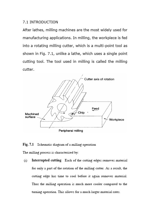
7.1 INTRODUCTIONAfter lathes, milling machines are the most widely used for manufacturing applications. In milling, the workpiece is fed into a rotating milling cutter, which is a multi-point tool as shown in Fig. 7.1, unlike a lathe, which uses a single point cutting tool. The tool used in milling is called the milling cutter.Fig. 7.1Schematic diagram of a milling operationThe milling process is characterised by:(i)Interrupted cutting Each of the cutting edges removes materialfor only a part of the rotation of the milling cutter. As a result, the cutting edge has time to cool before it again removes material.Thus the milling operation is much more cooler compared to the turning operation. This allows for a much larger material rates.(ii)Small size of chips Though the size of the chips is small, in view of the multiple cutting edges in contact a large amount of material is removed and as a result the component is generally completed ina single pass unlike the turning process which requires a largenumber of cuts for finishing.(iii)Variation in chip thickness This contributes to the non-steady state cyclic conditions of varying cutting forces during the contact of the cutting edge with the chip thickness varying from zero to maximum size or vice versa. This cyclic variation of the force can excite any of the natural frequencies of the machine tool system and is harmful to the tool life and surface finish generatedA milling machine is one of the most versatile machine tools. It is adaptable for quantity production as well as in job shops and tool rooms. The versatility of milling is because of the large variety of accessories and tools available with milling machines. The typical tolerance expected from the process is about ±0.050 mm.7.2 TYPES OF MILLING MACHINESTo satisfy various requirements milling machines come in a number of sizes and varieties. In view of the large material removal ratesmilling machines come with a very rigid spindle and large power. The varieties of milling machines available are:(i) Knee and Column type(a) horizontal(b) vertical(c) universal(d) turret typeThese are the general purpose milling machines, which have a high degree of flexibility and are employed for all types of works including batch manufacturing. A large variety of attachments to improve the flexibility are available for this class of milling machines.(ii) Production (Bed) type(a) simplex(b) duplex(c) triplexThese machines are generally meant for regular production involving large batch sizes. The flexibility is relatively less in these machines which is suitable for productivity enhancement.(iii) Plano millersThese machines are used only for very large workpieces involving table travels in meters.(iv) Special type(a) Rotary table(b) Drum type(c) Copy milling (Die sinking machines)(d) Key way milling machines(e) Spline shaft milling machinesThese machines provide special facilities to suit specific applications that are not catered to by the other classes of milling machines.7.2.1 Knee and Column Milling MachinesThe knee(升降台) and column type is the most commonly used machine in view of its flexibility and easier setup. A typical machine construction is shown in Fig. 7.2 for the horizontal axis. The knee houses the feed mechanism and mounts the saddle and table. The table basically has the T-slots running along the X-axis for the purpose of work holding. The table moves along the X-axis on the saddle while the saddle moves along the Y-axis on the guide ways provided on the knee.The feed is provided either manually with a hand wheel or connected for automatic by the lead screw, which in turn is coupled to the main spindle drive. The knee can move up and down (Z-axis) on a dovetail provided on the column.Fig. 7.2 Horizontal knee and column type milling machineThe massive column at the back of the machine houses all the power train including the motor and the spindle gearbox. The power for feeding the table lead screw is taken from the main motor through a separate feed gearbox. Sometimes a separate feed motor is provided for the feed gearbox as well.While the longitudinal and traverse motions are provided with automatic motion, the raising of the knee is generally made manually.The spindle is located at the top end of the column. The arbour used to mount the milling cutters is mounted in the spindle and is provided with a support on the other end to take care of the heavy cutting forces by means of an overarm with bearing. As shown in Fig.7.2 the overarm extends from the column with a rigid design. The spindle nose has the standard Morse taper of the suitable sizedepending upon the machine size.The milling cutters are mounted on the arbour at any desired position, the rest of the length being filled by standard hardened collars of varying widths to fix the position of the cutter. The arbour is clamped in the spindle with the help of a draw bar and then fixed with nuts.Milling machines are generally specified on the following basis:(i) Size of the table, which specifies the actual working area on the table and relates to the maximum size of the workpiece that can be accommodated.(ii) Amount of table travel, which gives the maximum axis movement that is possible.(iii) Horse power of the spindle, which actually specifies the power of the spindle motor used. Smaller machines may come with 1 to 3 hp while the production machines may go from 10 to 50 hp.Another type of knee and column milling machine is the vertical axis type. Its construction is very similar to the horizontal axis type, except for the spindle type and location.The vertical axis milling machine is relatively more flexible (Fig. 7.4) and suitable for machining complex cavities such as die cavities in tool rooms. The vertical head is provided with a swiveling facility in horizontal direction whereby the cutter axis can be swivelled. This isuseful for tool rooms where more complex milling operations are carried out.The spindle is located in the vertical direction and is suitable for using the shank mounted milling cutters such as end mills, In view of the location of the tool, the setting up of the workpiece and observing the machining operation is more convenient.Fig, 7.3 Vertical knee and column type milling machineFig.7.4 Some of the milling operations normally carried out on vertical axis machinesThe universal machine has the table which can be swivelled in a horizontal plane at about 45o to either the left or right. This makes the universal machine suitable for milling spur and helical gears as well as worm gears and cams.7.2.2 Bed Type Milling MachineIn production milling machines it is desirable to increase the metal removal rates. If it is done on conventional machines by increasingthe depth of cut, there is possibility of chatter. Hence another varietyof milling machines named as bed type machines are used which are made more rugged and are capable of removing more material. The ruggedness is obtained as a consequence of the reduction in versatility.The table in the case of bed type machines is directly mounted on the bed and is provided with only longitudinal motion.The spindle moves along with the column to provide the cutting action. Simplex machines (Fig. 7.5) are the ones with only one spindle head while duplex machines have two spindles (Fig. 7.6). The two spindles are located on either side of a heavy workpiece and remove material from both sides simultaneously.Fig. 7.5 Simplex bed type milling machineFig. 7.6 Duplex bed type milling machine7.3 MILLING CUTTERSThere are a large variety of milling cutters available to suit specific requirements. The versatility of the milling machine is contributed toa great extent by the variety of milling cutters that are available.7.3.1 Types of Milling CuttersMilling cutters are classified into various types based on a variety of methods.(i) Based on construction:(a) Solid(b) Inserted tooth typeBased on mounting:(a) Arbor mounted(b) Shank mounted(c) Nose mountedBase on rotation:(a) Right hand rotation (counter clockwise)(b) Left hand rotation (clockwise)Based on helix:(a) Right hand helix(b) Left hand helixMilling cutters are generally made of high speed steel or cemented carbides. The cemented carbide cutters can be of a brazed tip variety or with indexable tips. The indexable variety is more common since it is normally less expensive to replace the worn out cutting edges than to regrind them.Plain milling cutters These are also called slab milling cutters and are basically cylindrical with the cutting teeth on the periphery as shown in Fig. 7.7. These are generally used for machining flat surfaces.Fig. 7.7 Arbor mounted milling cutters for general purposeLight duty slab milling cutters generally have a face width, which is small of the order of 25 mm. They generally have straight teeth and large number of teeth.Heavy duty slab milling cutters come with a smaller number of teeth to allow for more chip space. This allows taking deeper cuts and consequently high material removal rates.Helical milling cutters have a very small number of teeth but a large helix angle. This type of cutter cuts with a shearing action, which can produce a very fine finish. The large helix angle allows the cutter to absorb most of the end load and therefore the cutter enters and leaves the workpiece very smoothly.Side and face milling cutters These have the cutting edges not only onthe face like the slab milling cutters, but also on both the sides. As aresult, these cutters become more versatile since they can be used for side milling as well as for slot milling.Staggered tooth side milling cutters are a variation where the teeth are arranged in an alternate helix pattern. This type is generally used for milling deep slots, since the staggering of teeth provides for greater chip space.Another variation of the side and face cutter is the half side milling cutter, which has cutting edges only on one side. This arrangement provides a positive rake angle and is useful for machining on only one side. These have a much smoother cutting action and a long tool life. The power consumed is also less for these cutters.Fig. 7.8Special forms of arbor mounted milling cuttersSlitting saws The other common form of milling cutters in the arbor mounted category is the slitting saw. This is very similar to a saw blade inappearance as well as function. Most of these have teeth around the circumference while some have side teeth as well. The thickness of these cutters is generally very small and is used for cutting off operations or for deep slots.Special form cutters In addition to the general type of milling cutters described above, there are a large number of special form milling cutters available which are used for machining specific profiles.Angular milling cutters are made in single or double angle cutters for milling any angle such as 30, 45 or 60o Form relieved cutters are made of various shapes such as circular, corner rounding, convex or concave shapes.T-slot milling cutters are used for milling T-slots such as those in the milling machine table. The central slot is to be milled first using an end mill before using the T-slot milling cutter. Woodruff key seat milling cutters are used for milling as the name suggests, woodruff key seats Some other special form cutters are dovetail milling cutters and gear milling cutters.End mills These are shank mounted as shown in Fig. 7.9 and are generally used in vertical axis milling machines. They are used for milling slots, key ways and pockets where other type of milling cutters cannot be used. A depth of cut of almost half the diameter can be taken with the end mills.The end mills have the cutting edge running through the length of the cutting portion as well as on the face radially up to a certain length. The helix angle of the cutting edge promotes smooth and efficient cutting even at high cutting speeds and feed rates. High cutting speeds(转速?) are generally recommended for this type of milling cutters.Fig. 7.9 Shank mounted milling cutters and various types of end mills There are a large variety of end mills. One of the distinctions is based on the method of holding, i.e., the end mill shank can be straight or tapered. The straight shank is used on end mills of small size and held in the milling machine spindle with the help of a suitable collet. The tapered shank can be directly mounted in the spindle with the help of the selfholding taper. If the taper is small compared to the spindle taper, then an adopter accommodating both the tapers is used.The end teeth of the end mills may be terminated at a distance from the cutter center or may proceed till the center (Fig. 7.9 f). Those with the cutting edge up to the center are called slot drills or end cutting end mills since they have the ability to cut into the solid material (Fig. 7.9 g). The other type of end mills which have a larger number of teeth cannot cut into solid material and hence require a pilot hole drilled before a pocket is machined.The cutting edge along the side of an end mill is generally straight and sometimes can be tapered by grinding on a tool and cutter grinder such that the draft required for mould and die cavities can be automatically generated.第七章铣削7.1介绍除了车床,铣床是制造应用中最广泛使用的。
X62W铣床数控化改造外文文献翻译、中英文翻译、外文翻译

X62W CNC milling machine transformation1 general CNC transformation of the need for analysisOur about 3200000 existing machine tools, the machine tool technol ogy status of ageing is serious, according to statistics, about 30% of the total country equipment in more than 16 years, of which nearly 30% of age more than 26 years, all these show the present our country did no t go mainly rely on progress of science and technology of machine tools to transform track. In addition, with the development of science and tec hnology, production is dependent on the degree of equipment increases i ncreasingly, the crop of the enterprise, quality, efficiency, cost, safety an d environmental protection and labor emotions get equipment restrict, rea lize the modernization of enterprise oneself be imperative. But according to the data, our metal cutting machine tool production only accounted for similar equipment to have an amount 1 / 28, such as the annual produ ction of all the machines used to replace the old machine tool needs 28 years so, our country is solved at present equipment technical progress is the main way of machine tools.2 domestic and foreign research present situationIn today's world, industrial developed country to machine tool industr y height seriously, competing for the development of mechanical and ele ctrical integration, high precision, high efficiency, high automation and ad vanced machine tool, in order to accelerate the industrial and economic development. For a long time, Europe and the United States, Asia in the international market are in fierce competition, has formed an invisible fr ont, especially with microelectronics, computer technology, numerical cont rol machine tools in the nineteen eighties later accelerated development, put forward more requirements of all users, had become the four big int ernational machine tool exhibition to display machine tool manufacturers advanced technology, for the user, enlarge the market focus. The more f amous control system : Japan FANUC series, Mitsubishi series, OKUNIA series, SODICK series, series of Hitachi, Germany SIEMENS series, DE CKEL series, Heidenhain series, HELLER series, the United States ALLE N-BRADLEY ( AB ) series, CINCINNANTI series, Num series, FIDIA seri es of France, Italy, Spain, Switzerland FAGOR series, AG series of dom estic series.In the United States, Japan and Germany and other developed coun tries, they will machine transformation as a new economic growth sector, the business scene, is in the golden age. As the machine tool and the continuous advancement of technology, machine tools transformation is a "timeless" issue. Transformation of China's machine tool industry, but a lso from the old to the industry into the digital technology-based new industries. In the United States, Japan, Germany, with machine tool of num erical control technical reformation and production line has a broad mark et, has formed a production line of CNC machine tool and the new indu stry. In the United States, reconstruction of machine tool industry called machine regeneration ( Remanufacturing ) industry. Engaged in renewabl e industry's well-known companies: Bertsche engineering company, ayton machine tool company, Devlieg-Bullavd ( PO ) services group, US equi pment company. The United States company has been in China for the company. Rebuilding of machine tool industry in Japan called machine m odified ( Retrofitting ) industry. Engaged in refitting industry well-known c ompanies have: Doomsday engineering group, three post machinery com pany, Chiyoda engineering machine company, Nozaki engineering compa ny, Hamada engineering company, Yamamoto engineering company.Catch up with the pace of computer system structure, accelerate the development of NC system for NC development speed, has become the main trend. The fourth generation computer engineering structure and m icroelectronic technology as the basis, make full use of existing computer hardware, software resources, development of bus type, module type, o pen type, embedded on a flexible NC system, which is suitable for mach ining complex parts, vertical machine tool with CNC system, but also for future automation upgrades the function may be expanded requirements.China 's NC system development has the following 3 features:( 1 ) system of high-grade numerical control technology has been a breakthrough. As of I type numerical control system, with multi axis linka ge function, fast feed speed in 1.67m / s above, have stronger communi cation, management function.( 2) universal CNC system is a mature technology. Beijing Machine Tool Research Institute BS9l system, these systems are generally equipp ed with CRT display, can be configured to DC and AC servo drive, 2 ~ 4 shaft linkage.( 3) the economic type CNC system still has vast market prospect. As a result of this kind of system has the advantages of simple structur e, cheap price, very suitable for small and medium enterprises in China,is still the most widely applied in CNC system. A typical Nanjing gener ous JWK series.Our country is big country of production of machine tools, it is the u se of power. NC machine tool is the key to the development of machine ry industry products, China's CNC machine tool in machine tool products in the proportion of the overall low level of. But our country is a develo ping country, a lot of enterprises financial weakness, not likely to spend a lot of money on a lot of new CNC machine tools, while a large numb er of universal machine tool can not be all eliminated.Therefore, the transformation of general machine tools CNC machine is a effective way to improve the rate of NC machine tools transformati on, less cost, reform targeted, time is short, after the transformation of t he machine tool are able to overcome the original machine faults and pr oblems, high production efficiency.3 basic scheme comparison and selectionNC transformation of the main general plan shall include the followin g contents: the servo drive system, numerical control device selection, el ectrical equipment, mechanical design, CNC hardware system. Show cent to narrate as follows.The 3.1 servo drive systemServo system is a important part of NC machine tool, its performanc e will directly affect the machining accuracy, surface quality and producti on efficiency, it can be divided into 3 kinds, namely, open loop, closed l oop, loop.3.1.1 open loop systemOpen loop system is the most simple servo, stepper motor as the o pen loop system main device, it has the advantages of simple structure ( electrical control and drive circuit is simple ), small volume, light weight, low price, convenient repair and maintenance characteristics3.1.2 closed loop systemClosed loop system, its structure is complex, technical difficulty is gr eat, testing and repair more difficult, cost is high. Closed loop control ca n achieve good accuracy of machine tools, to compensate for mechanica l transmission system in a variety of error, eliminate the gap, interferenc e on the accuracy of processing, generally applied to the high requireme nts of NC equipment.3.1.3 semi closed loop systemSemi closed loop system with closed-loop system similar to, the posi tion detection device is mounted on the execution component, but mount ed on the drive motor end or the end of the drive rod, indirectly measur ed actuator position or displacement. Due to its wide range of speed ( 0.1 - 3OOO R / rain ), strong overload capacity, and the feedback control, the precision can reach 0.01 ~ 0.001nlln, as fast as 0.5 m / s, so its p erformance is far superior to the stepping motor open loop control, and t he feedback link does not include most of mechanical transmission comp onents, simple debugging ratio closed loop, the system stability can be e asily ensured, than the closed loop is easy to realize. Therefore, using a closed-loop system, is more reliable and feasible.3.1.4 AC, DC servo motor comparisonClosed loop, half closed loop system can be AC or DC servo motor, the AC speed regulation gradually expanding the scope of application, s eems to have replaced DC servo trend. But AC servo control of complic ated structure, high technical difficulty, popularity is not wide, and the pri ce is high ( DC servo motor 1.5 ~ 20000 yuan / Taiwan, AC servo mot or is 2 - 30000 ) in addition, compared to the DC servo motor AC serv o motor with large inertia, the small inertia, debugging difficulty big, whe n the sources are more difficult to repair components. DC servo motor p rinciple similar to DC motor, control system technology is more mature, spread wide, its main drawback is the large volume, large weight, but als o with the commutator and brush, increased repair workload.Through the comparison, the success rate, technical difficulty, precisi on and investment and other factors, decided to adopt DC servo loop co ntrol.3.2 numerical control deviceNumerical control device also has a variety of scheme selection. For example, can all of its own design, production; can use SBCs or STD module control; can use readily available numerical control device for a small number of applicable changes or matching. In the factory's practica l application, generally use the following 2 kinds of solution. A kind of cir cumstance is required for the function and requirement of ready-made C NC device can meet, then used mostly to buy ready-made products solu tion, because of own design is not only a waste of time, investment is n ot necessarily can save investment, more often, and quality do not nece ssarily guarantee. Another kind of circumstance is not to buy off-the-shelf products to achieve some special function, then mostly adopt buy price performance ratio as high performance close to the device, and then to supplement or transformation, at least also bought STD template or indu strial control computer, single board computer to make.According to the selected DC servo drive and processing requiremen ts, the numerical control device can realize closed loop ( loop ) of contr ol, provides the analog control signal, receives the half closed loop feed back signal to control; three coordinate axis of motion, wherein at least t o simultaneously control linkage to complete the arc differential complem ent; in the processing of can use different size cutter, CNC device with cutting tool radius and length compensation in NC machining, so accordi ng to the contour programming and can adapt to the size of tool change, in order to meet the needs of future development and clear structure, d ecided to adopt the STD template, modular design.3.3 other electrical devicesIn numerical control transformation, also needs to be combined with the numerical control device and servo drive configuration characterized by other electrical parts, including the strong and weak electrical signal c onversion, transmission or processing necessary. The input / lucky bird o ut interface to consider whether isolation, shielding requirements; in additi on, but also configure the needed power, all kinds of protection circuit, a uxiliary circuit detecting display.3.4 mechanical partsIn the equipment of numerical control transformation, although is the core part of CNC, involve more is microelectronics and electrical, but n ot of all. If you ignore the mechanical aspects according to the character istics of CNC machine tools for the corresponding necessary changes, or in the transformation of the design and manufacture of endless and rea sonable, the results will give numerical control transformation brings beat all difficulties, and may even lead to failure because of mechanical prob lems.3.5 CNC numerical control systemThe CNC system is composed of CPU memory template; servo mot or interface circuit board; the keyboard, display interface circuit board an d a switch quantity input, output interface circuit board. Each template m ain function is as follows.3.5.1CPU memory boardThe board carried out various data operations, timer in the interventi on, timing execution system program, coordination, management of vario us parts of the circuit to work.In addition, also has a power down protection, power on reset and generates a pulse signal and other functions. At the same time, board m emory, for storing system software, computing the results of staging and storage parts processing program. Plate communicationInterface for the boards and peripherals to provide a convenient com munication.3.5.2 servo motor interface circuit boardThe plate is connected to the servo motor and the CPU bridge. CP U issued a servo motor control instruction code, through the template D / A conversion, operational amplifier after being sent to the motor drive s ource, thus realizing the electrical automatic control. At the same time th e motor running state, through the detecting device of the pulse, in the plate after processing, in the form of code into CPU, CPU adjust motor control instruction, thereby forming displacement closed loop system. If th e pulse signal by F / V conversion, can get the speed control unit feedb ack voltage, which constitute a closed loop system.X62W铣床数控化改造1.普通机床数控化改造的必要性分析我国现有机床320多万台,这些机床技术状况老化严重,据统计,全国30%左右设备在16年以上,其中近30%的役龄超过了26年,这些都说明目前我国还没有走上主要依靠科技进步对机床进行改造的轨道。
分析数控机床改造外文文献翻译、中英文翻译、外文翻译

Analysis of transformation of numerical controlmachine toolIn order to survival and development of enterprises, improve the rate of CNC machine tools is necessary. Transformation of the equipment needed for NC machine tools in general, including traditional and recently introduced from abroad, due to a problem can not be put into the machine tool equipment and production lines. First, transform the contents of the NCCNC machine tools and production line transformation of the main contents are: (1) restoration of the original function, machine tools, production lines there is some fault diagnosis and recovery; (2)NC-based, in the general machine tools addend remarkable device or add numerical control system; ( 3) The renovation, to improve accuracy, efficiency and degree of automation, mechanical, electrical parts of the renovation, the mechanical part of there-assembly process, to restore the original precision; can not meet the production requirements of its CNC system be updated with the latest CNC; (4) technology updates or technical innovation, in order to improve performance or grade, or for the use of new technology, new technology, based on the original large-scale technology updates or technical innovation.Second, the development trend of CNC systeml. To open, the sixth generation of PC-based directionThe openness of the PC-based, low-cost, high reliability, rich in natural resources such as hardware and software features, and more CNC system manufacturer will be to go down this path. At least with PC, as its front-end machines, to deal with man-machine interface, programming, networking and communications issues, the original system to take over some tasks PC CNC machines has the friendly interface, will reach all of the CNC system. The remote communication, remote diagnostics and maintenance of applications will be more common.2. To the development of high-speed and high precision.3. To the intelligent direction(1) The application of adaptive control technology. Numerical control system can detect the process of important information and automatically adjust system parameters, improving the system operation status.2) the introduction of expert systems to guide processing. Will be skilled workers and expertise, processing and general laws and special laws into the system to process parameter database support, establish an artificial intelligence expert system.(3) the introduction of fault diagnosis expert system(4) intelligent digital servo drives. Can automatically identify the load and automatically adjust the parameters of the drive system to get the best state of operation.Third, the choice of numerical control system1. Open-loop systemThe system's servo-driven device is a stepper motor, power stepper motors, electro-hydraulic pulse motors. This system does not require position and velocity feedback, displacement accuracy depends mainly on the angular displacement precision stepper motor and gear drive components such as precision screw, so displacement of low accuracy. But the system is simple, debugging easy maintenance, reliable, low cost, easily converted successfully.2. Closed-loop systemThe system consists of grating, sensor position detection device synchronization, etc. The actual measured position signal fed back to the computer, compared with a given value, the difference between the two amplification and transformation, driving the implementing agencies in order to eliminate bias. The system complexity, high cost and strict temperature requirements on the environment. But thesystem of high precision, speed and big power. According to technological requirements and decide whether to adopt.3. Semi-closed-loop systemSemi-closed-loop system detects components installed in the middle of transmission parts, the indirect measurement of the location of the implementation of parts. It can only compensate for part of the components within the system loop error, and therefore its more accurate than the accuracy of closed-loop system is low, but its structure and debugging as compared with the closed-loop system is simple.Current production numerical control system are more companies and manufacturers, foreign companies such as Siemens of Germany, Japan, Fanuc, Inc.; domestic Everest companies such as China, the Beijing Aerospace CNC System Corporation, Huazhong CNC CNC high-grade corporate and Shenyang National Engineering Research Center. Select CNC systems are mainly based on numerical control after transformation to be achieved in a variety of precision machine tools, drive motor power and the user's requirements to determine. Fourth, the main steps CNC transformation1. Determination of rehabilitation programs(1) Mechanical and Electrical Repair transformation combined.Generally speaking, in need of transformation of electrical machines, are in need of mechanical repair. To determine repair requirements, scope and content; have to ascertain the electrical modification of the mechanical structure in need of transformation requirements and content; but also determine the transformation of electrical and mechanical repair, reconstruction staggered between the time requirements. Mechanical properties of intact are electrical transformation success.(2) the easier issues first, after the first partial overall. Determine the transformation step, the whole electrical part of the transformation should be divided into several sub-systems, the basic shape of various systems to be connected after the completion of the whole system work. In each subsystem, we should do first the less technical, workload the larger work, and then do a technical high, requiring fine work, can focus people's attention to key areas.(3) selection system under conditions of use. For the transformation of the object to determine its environment and conditions, which the selection of electrical system protection, anti-jamming, self-cooling and air filtering performance can provide the correct basis. Electrical system options must also be considered mature products, their performance should be reasonable and practical, there are spare parts to provide maintenance support, features a number of years to meetthe current and future development requirements.(4) The implementation and responsibilities of personnel involved in reconstruction.(5) The transformation of the determination of the scope and cycle.2. Transformation of the technical preparation(1) mechanical parts ready. In line with the transformation of mechanical electrical repairs should be completed in advance. The same time, be demolished and replaced and processing should be part of such advance planning is necessary to properly interface with the entire transformation.(2) The electrical information on the new system to digest.(3) The conversion of the old system interface design. According to the scope of each of the different equipment modification required to pre-designed interface, part of the conversion, if the entire transformation should be designed to convert mechanical and electrical interfaces, operation panel control and configuration, the Internet part of the contact, parameter measurement, the maintenance and so on. Require the operation and maintenance easy and reasonable, alignments, fluent, primary and secondary connection point less electrical interference with the strength of the smallest, with an appropriate margin and so on. Local transformation, but also need to consider the performance of the system match theold and new, the voltage polarity and size of change, the installation location, digital-analog conversion, etc., if necessary, need to create their own interfaces.(4) operation and programming staff technical training. ①training should cover the new control panel configuration, function and meaning of the instructions; ②the scope of the new system features, use, and the difference between the old system; ③maintenance requirements; ④programming standards and automated programming and more. Focused understood, grasp operating instructions and programming instructions.(5) Debugging steps and acceptance criteria for the determination. Debugging should be done by the project leader carried out with the others. Debugging step can be from simple to complex, from small to large, from outside to inside, you can also after the first local situation, the whole system after the first subsystem. The development of acceptance criteria must be realistic, too high or too low a standard will have a negative impact on the transformation.3. The implementation of reform(1) The overall maintenance of the machine. The long-term use of the original machine, you need to conduct a comprehensive maintenance. Secondly, the response to machine tools to make achange before the geometric accuracy, dimensional accuracy of measurement, and for the record. In this way pairs of reference to guide the transformation of the role, but also in the transformation of the end for comparison analysis.(2) to retain the electrical adjustment of some of the best. If the electrical system as part of the transformation, in turn, should retain the parts of the maintenance and optimization adjustments, such as high power part of the spare parts replacement, electrical maintenance, drying transformer insulation, pollution, cleaning, ventilation and cooling equipment cleaning, servo Drive optimization adjustments, update aging wires and cables, connectors and other fastening. Only the electrical part of the reservation and do excellent optimization adjustment, in order to ensure that transformed the machine tool have lower failure rates.(3) The original systems were dismantled. The removal of the original system must be controlled carefully to the original drawings in time to make mark in the drawings to prevent the omission or been demolished. In the process of demolition will find some of the new system design in the gaps, it is timely to add and correction. Removed the system should be properly safeguarded in case of unsuccessful reconstruction resume use. There is a definite value, and can be used for spare parts.(4) reasonable arrangements for the location and wiring the new system. Connection must be a clear division of labor, there is one person review the inspection to ensure that the connection process specifications, diameter suitable, correct, reliable and beautiful. (5) debugging. Debug must be pre-established procedures and requirements. Debugging the first to test the safety protection system sensitivity, personal and equipment to prevent accidents. Debugging the site must be clean; the moving coordinate extension units at the center of the whole trip; be able to load test, the first no-load after load; can simulate the experiment, the first real action after simulated; be manual, first manually and automatically.4. Acceptance and post-work(1) The mechanical properties of machine tool acceptance. Machine tool should meet the requirements of the mechanical properties, geometric accuracy should be within the limits prescribed.(2) The electrical control functions and control accuracy and acceptance. The various functions of electrical control actions must meet the normal, sensitive and reliable. Control precision application system itself functions (such as step size, etc.) and standard measuring apparatus (such as laser interferometer, coordinate measuring machine, etc.) control checks, to reach within a range. Should also be modified before the machine with the functions andaccuracy to make comparison, access to quantifiable indicators of difference.(3) The test piece cutting and acceptance. Can refer to the relevant domestic and international standards for CNC cutting specimens, in a qualified operator, the programmer with the trial under the cut. Specimen cutting machine tools can be acceptance of stiffness, cutting force, noise, motion trajectory, related actions, are generally not suitable for specimen use of a product part.(4), drawings, information and acceptance. Machine transformation finished, should be promptly drawings, data, transform the file summary, collate, transfer into the file. This is the future and stable operation of the equipment is very important.(5) Summary and improve.5, numerical examples of reconstruction1. Milling machine with the Siemens 810M transformation X53In 1998, the company invested 200,000 yuan, with Germany's Siemens 810M CNC system, 611A AC servo drive system on the company's X53 model of a milling machine to X, Y, Z three-axis numerical control transformation. Retained the original spindle system and cooling system. -Axis transformation of a ball screw used in the machinery and gear transmission mechanism. Thetransformation of work includes mechanical design, electrical design, PLC program preparation and debugging, machine tool repair, machine installation and debugging. After transformation, milling, processing and effective travel X, Y, Z axis respectively, 880mm, 270mm, 280mm; maximum speed of X, Y, Z axis respectively, 5 000mm/min, 1 500mm/min, 800mm/min; point moving speed of X, Y, Z axis respectively 3 000mm/min, 1 000mm/min, 500 mm / min; machining accuracy of ± 0.001 mm. Machine tools, coordinate linkage to be completed by a variety of complex curve or surface processing.2. GSK980T and stepper drive system with the transformation ofC6140 latheIn 1999, the company invested 8 million yuan, with Guangzhou CNC Equipment Factory production GSK980T numerical control system, DY3 hybrid stepper drive unit on the company's a longerC6140 lathe X, Z 2-axis transform. Retained the original spindle system and cooling system. Transformation of two-axis ball screw in the machinery used, and synchronous transmission. The transformation of work includes mechanical design, electrical design, machine overhaul and machine installation and debugging. Lathe After the transformation, processing and effective stroke X, Z axis respectively, 390mm, 1400mm; maximum speed X, Z axisrespectively, 1 200mm/min, 3 000mm/min; jog speed 400mm/min; point moving fast X, Z-axis respectively, 1 200mm/min, 3000mm/min; machine smallest mobile unit 0.001mm.6, numerical transformation of the issues and recommendations1. Transformation problems in NCCNC machine tools through several transformation and found work, there are also many problems, mainly reflected in: (a) The departments, developers uncertain functions, organizational chaos, a serious impact on progress in the transformation; (2) to develop the work process and plans are mostly developed rule of thumb, less reasonable; (3) the training of relevant personnel is not in place, resulting in machine tool technology officers will not be modified after programming, the operator of the machine operator unskilled and so on.2. Transformation of the proposed NC(1) is responsible for transformation of the staff responsibilities of clear penalties and rewards, fully mobilize the enthusiasm of the staff; train a batch of high-quality applications and maintenance personnel, training for selected officers to go out and learn the advanced technologies;(2) To focus on users, maintenance of CNC system of technicaltraining, the establishment of numerical control technology at home and abroad resource library. The establishment of technical data files, do the work of spare parts.分析数控机床改造为了我国民营企业的生存与发展,提高数控机床的速度是必要的。
机床行业中英文对照

机床行业中英文对照机床行业中英文对照3-Jaws indexing spacers 三爪、分割工具头A.T.C.system 加工中心机刀库Aluminum continuous melting & holding furnaces 连续溶解保温炉Balancing equipment 平衡设备Bayonet 卡口Bearing fittings 轴承配件Bearing processing equipment 轴承加工机Bearings 轴承Belt drive 带传动Bending machines 弯曲机Blades 刀片Blades,saw 锯片Bolts,screws & nuts 螺栓,螺帽及螺丝Boring heads 搪孔头Boring machines 镗床Cable making tools 造线机Casting,aluminium 铸铝Casting,copper 铸铜Casting,gray iron 铸灰口铁Casting,malleable iron 可锻铸铁Casting,other 其他铸造Casting,steel 铸钢Chain drive 链传动Chain making tools 造链机Chamfer machines 倒角机Chucks 夹盘Clamping/holding systems 夹具/支持系统CNC bending presses 电脑数控弯折机CNC boring machines 电脑数控镗床CNC drilling machines 电脑数控钻床CNC EDM wire-cutting machines 电脑数控电火花线切削机CNC electric discharge machines 电脑数控电火花机CNC engraving machines 电脑数控雕刻机CNC grinding machines 电脑数控磨床CNC lathes 电脑数控车床CNC machine tool fittings 电脑数控机床配件CNC milling machines 电脑数控铣床CNC shearing machines 电脑数控剪切机CNC toolings CNC刀杆CNC wire-cutting machines 电脑数控线切削机Conveying chains 输送链Coolers 冷却机Coupling 联轴器Crimping tools 卷边工具Cutters 刀具Cutting-off machines 切断机Diamond cutters 钻石刀具Dicing saws 晶圆切割机Die casting dies 压铸冲模Die casting machines 压铸机Dies-progressive 连续冲模Disposable toolholder bits 舍弃式刀头Drawing machines 拔丝机Drilling machines 钻床Drilling machines bench 钻床工作台Drilling machines,high-speed 高速钻床Drilling machines,multi-spindle 多轴钻床Drilling machines,radial 摇臂钻床Drilling machines,vertical 立式钻床drills 钻头Electric discharge machines(EDM) 电火花机Electric power tools 电动刀具Engraving machines 雕刻机Engraving machines,laser 激光雕刻机Etching machines 蚀刻机Finishing machines 修整机Fixture 夹具Forging dies 锻模Forging,aluminium 锻铝Forging,cold 冷锻Forging,copper 铜锻Forging,other 其他锻造Forging,steel 钢锻Foundry equipment 铸造设备Gear cutting machines 齿轮切削机Gears 齿轮Gravity casting machines 重力铸造机Grinder bench 磨床工作台Grinders,thread 螺纹磨床Grinders,tools & cutters 工具磨床Grinders,ultrasonic 超声波打磨机Grinding machines 磨床Grinding machines,centerless 无心磨床Grinding machines,cylindrical 外圆磨床Grinding machines,universal 万能磨床Grinding tools 磨削工具Grinding wheels 磨轮Hand tools 手工具Hard/soft and free expansion sheet making plant 硬(软)板(片)材及自由发泡板机组Heat preserving furnaces 保温炉Heating treatment funaces 熔热处理炉Honing machines 搪磨机Hydraulic components 液压元件Hydraulic power tools 液压工具Hydraulic power units 液压动力元件Hydraulic rotary cylinders 液压回转缸Jigs 钻模Lapping machines 精研机Lapping machines,centerless 无心精研机Laser cutting 激光切割Laser cutting for SMT stensil 激光钢板切割机Lathe bench 车床工作台Lathes,automatic 自动车床Lathes,heavy-duty 重型车床Lathes,high-speed 高速车床Lathes,turret 六角车床Lathes,vertical 立式车床Lubricants 润滑液Lubrication Systems 润滑系统Lubricators 注油机Machining centers,general 通用加工中心Machining centers,horizontal 卧式加工中心Machining centers,horizontal & vertical 卧式及立式加工中心Machining centers,vertical 立式加工中心Machining centers,vertical double-column type 立式双柱加工中心Magnetic tools 磁性工具Manifolds 集合管Milling heads 铣头Milling machines 铣床Milling machines,bed type 床身式铣床Milling machines,duplicating 仿形铣床Milling machines,horizontal 卧式铣床Milling machines,turret vertical 六角立式铣床Milling machines,universal 万能铣床Milling machines,vertical 立式铣床Milling machines,vertical & horizontal 立式及卧式铣床Mold & die components 模具单元Mold changing systems 换模系统Mold core 模芯Mold heaters/chillers 模具加热器/冷却器Stamping parts 冲压机Straightening machines 矫直机Switches & buttons 开关及按钮Tapping machines 攻螺丝机Transmitted chains 传动链Tube bending machines 弯管机Vertical hydraulic broaching machine 立式油压拉床Vises 虎钳Vises,tool-maker 精密平口钳Wheel dressers 砂轮修整器Woven-Cutting machines 织麦激光切割机Wrenches 扳(2):按中文拼音字母排序铝轮冒口切断机 Overflow cutting machines for aluminium wheels 离心压力机 Presses,eccentric六角立式铣床 Milling machines,turret vertical六角车床 Lathes,turret螺栓,螺帽及螺丝 Bolts,screws & nuts螺纹磨床 Grinders,thread冷却机 Coolers冷锻 Forging,cold冷锻冲压机 Presses,cold forging立式双柱加工中心 Machining centers,vertical double-column type 立式铣床 Milling machines,vertical立式油压拉床 Vertical hydraulic broaching machine立式刨床 Planing machines vertical立式车床 Lathes,vertical立式带锯 Saws,vertical band立式加工中心 Machining centers,vertical立式及卧式铣床 Milling machines,vertical & horizontal立式钻床 Drilling machines,vertical联轴器 Coupling连续溶解保温炉 Aluminum continuous melting & holding furnaces 连续冲模 Dies-progressive链传动 Chain drive切断机 Cutting-off machinesCNC刀杆 CNC toolings曲柄压力机 presses,crank修整机 Finishing machines舍弃式刀头 Disposable toolholder bits润滑系统 Lubrication Systems润滑液 Lubricants熔热处理炉 Heating treatment funaces三爪、分割工具头 3-Jaws indexing spacers伺服冲床 Presses,servo输送链 Conveying chains手工具 Hand tools砂轮修整器 Wheel dressers蚀刻机 Etching machines外圆磨床 Grinding machines,cylindrical搪磨机 Honing machines搪孔头 Boring heads卧式铣床 Milling machines,horizontal卧式带锯 Saws,horizontal band卧式加工中心 Machining centers,horizontal卧式及立式加工中心 Machining centers,horizontal & vertical万能铣床 Milling machines,universal万能磨床 Grinding machines,universal镗床 Boring machines弯曲机 Bending machines弯管机 Tube bending machines通用加工中心 Machining centers,general铜锻 Forging,copper铣头 Milling heads铣床 Milling machines无心磨床 Grinding machines,centerless无心精研机 Lapping machines,centerless压模 Pressing dies压铸冲模 Die casting dies压铸机 Die casting machines油冷却器 Oil coolers造链机 Chain making tools造线机 Cable making tools造钉机 Nail making machines印刷电器板油压冲孔脱料系统 PCB fine piecing systems摇臂钻床 Drilling machines,radial硬(软)板(片)材及自由发泡板机组 Hard/soft and free expansion sheet making plant 辗压机 Rolling machines液压元件 Hydraulic components液压冲床 Presses,hydraulic液压动力元件 Hydraulic power units液压工具 Hydraulic power tools液压回转缸 Hydraulic rotary cylindersP型PVC高分子防水 P type PVC waterproof rolled sheet making plant刨床 Planing machines牛头刨床 Shapers其他铸造 Casting,other其他锻造 Forging,other模芯 Mold core模具 Molds模具维修 Mold repair模具打磨/磨纹 Mold polishing/texturing 模具单元 Mold & die components模具加热器/冷却器 Mold heaters/chillers 磨轮 Grinding wheels磨削工具 Grinding tools磨床 Grinding machines磨床工作台 Grinder bench平衡设备 Balancing equipment气油压虎钳 Pneumatic hydraulic clamps 气动冲床 Presses,pneumatic气动工具 Pneumatic power tools轴 shafts轴承 Bearings轴承配件 Bearing fittings轴承加工机 Bearing processing equipment 肘杆式压力机 Presses,knuckle joint铸铝 Casting,aluminium铸铜 Casting,copper铸造设备 Foundry equipment铸钢 Casting,steel铸灰口铁 Casting,gray iron织麦激光切割机 Woven-Cutting machines 重力铸造机 Gravity casting machines重型车床 Lathes,heavy-duty主轴 spindles扳手 Wrenches拔丝机 Drawing machines保温炉 Heat preserving furnaces插床 Slotting machines齿轮 Gears齿轮切削机 Gear cutting machines冲压机 Stamping parts冲子研磨器 Punch formers超声波打磨机 Grinders,ultrasonic车床工作台 Lathe bench磁性工具 Magnetic tools传动链 Transmitted chains床身式铣床 Milling machines,bed type带传动 Belt drive带锯 Saws,band带锯床 Sawing machines,band电脑数控镗床 CNC boring machines电脑数控弯折机 CNC bending presses电脑数控铣床 CNC milling machines电脑数控线切削机 CNC wire-cutting machines电脑数控磨床 CNC grinding machines电脑数控车床 CNC lathes电脑数控电火花线切削机 CNC EDM wire-cutting machines 电脑数控电火花机 CNC electric discharge machines电脑数控雕刻机 CNC engraving machines电脑数控机床配件 CNC machine tool fittings电脑数控剪切机 CNC shearing machines电脑数控钻床 CNC drilling machines电动刀具 Electric power tools电火花机 Electric discharge machines(EDM)雕刻机 Engraving machines刀片 Blades刀具 Cutters倒角机 Chamfer machines多轴钻床 Drilling machines,multi-spindle锻铝 Forging,aluminium锻压机 Presses,forging锻模 Forging dies仿形铣床 Milling machines,duplicating粉末冶金成型机 Powder metallurgic forming machines 反射炉 Reverberatory furnaces钢锻 Forging,steel高速车床 Lathes,high-speed高速钻床 Drilling machines,high-speed管筒制造机 Pipe & tube making machines滚筒 Rollers工具磨床 Grinders,tools & cutters攻螺丝机 Tapping machines弓锯 Saws,hack虎钳 Vises换模系统 Mold changing systems夹盘 Chucks夹具 Fixture夹具/支持系统 Clamping/holding systems剪切机 Shearing machines加工中心机刀库 A.T.C.system激光切割 Laser cutting激光雕刻机 Engraving machines,laser激光钢板切割机 Laser cutting for SMT stensil集合管 Manifolds矫直机 Straightening machines金属板成型机 Sheet metal forming machines 金属板加工机 Sheet metal working machines 锯片 Blades,saw锯床 Sawing machines卷边工具 Crimping tools晶圆切割机 Dicing saws精密平口钳 Vises,tool-maker精研机 Lapping machines可锻铸铁 Casting,malleable iron快速换模系统 Quick mold change systems卡口 Bayonet开关及按钮 Switches & buttons钻石刀具 Diamond cutters钻头 drills钻模 Jigs钻床 Drilling machines钻床工作台 Drilling machines bench自动压力机 Presses,transfer自动车床 Lathes,automatic注油机 Lubricators转台 Rotary tables。
- 1、下载文档前请自行甄别文档内容的完整性,平台不提供额外的编辑、内容补充、找答案等附加服务。
- 2、"仅部分预览"的文档,不可在线预览部分如存在完整性等问题,可反馈申请退款(可完整预览的文档不适用该条件!)。
- 3、如文档侵犯您的权益,请联系客服反馈,我们会尽快为您处理(人工客服工作时间:9:00-18:30)。
(文档含英文原文和中文翻译)中英文对照外文翻译原文:Design Of Tool Machine PropResearch significanceThe original knife machine control procedures are designed individually, not used tool management system, features a single comparison, the knife only has to find the tool knife, knifepositioning the shortest path, axis tool change, but does not support large-scale tool.Automatic knife in the knife election, in the computer memory knife-election on the basis of using the Siemens 840 D features, and the election procedures knife more concise, and complete the space Daotao View. ATC use the knife rapid completion of STEP-7 programming, and have been tested in practice. In the positioning of the knife, PLC controlled modular design method, which future production of similar machines will be very beneficial, it is easy to use its other machine. Automatic tool change systems will be faster growth, reduced tool change time, increase the positioning accuracy tool is an important means to help NC technology development.Tool and inventory components of modern production is an important link in the management, especially for large workshop management. The traditional way of account management, and low efficiency, high error rate, and not sharing information and data, tools and the use of state can not track the life cycle, are unable to meet the current information management needs. With actual production, we have to establish a workshop tool for the three-dimensional tool storage system to meet the knife workshop with auxiliary storage and management needs.The system uses optimization technology, a large number of computer storage inventory information, timely, accurate, and comprehensive tool to reflect the inventory situation. The entire system uses a graphical interface, man-machine dialogue tips from the Chinese menu, select various functions can be realized and the importation of all kinds of information. Management system using online help function. Through the workshop management, network management and sharing of information. Have automated inventory management, warehousing management tool, a tool for the management and statistical functions.1.System components and control structureThe entire system, including the structure and electrical machinery control systems.1.1.1Mechanical structure and working principleTool from the stent, drive, drive system, Turret, shielding, control system, and electrical components. Support from the column, beam, the upper and lower guide Central track, and track support component.1) Drive for the system chosen VVVF method. Cone used brake motors, with VVVF by Cycloid reducer through sprocket drive.2) Drag a variable frequency drive system and control technology. VVVF adopted, will speed drive shaft in the normal range adjustment to control the speed rotary turret to 5 ~ 30mm in, the drive shaft into two, two under through sprocket, the two profiled rollers Chain driven rotating shelves. Expansion chain adopted by the thread tight regulation swelling, swelling the regular way. - Conditioned, under the same chain-of-conditioning, so that the chain of uniform.3) Turret and shields the entire total of 14 independent Turret. 13 of them as a socket-Turret, as a drawer-Turret, each Turret back through the pin and, under the conveyor chain link chain plate, installed at the bottom roller, chain driven rotating turret rotation along the track. Outlet-Turret and BT50-BT40 Turret Turret two kinds of forms. To strengthen management, security, landscaping modeling, shelf peripherals and shields. Turret-drawer drawer placed at six other Des V oeux a knife, can be categorized with some of knife auxiliary equipment, such as bits, such as turning tools.1.1.2.Electrical Control SystemThis tool storage systems is the main electrical control their shelves for operational control and position control. Operational control equipment, including operation of the start of braking control. Position Control is the main location and address of the shelves for testing. Control system as shown in Figure 1.图 1 Tool Control System1) Electric Transmission horizontal rotary tool storage systems are the mechanical movements are repeated short-term work system. And the run-time system needs some speed, speed transmission needs, the system will use VVVF method can be used simple structure, reliable operation of the motor and frequency inverter.2) Control of the system is divided into two kinds of manual control and automatic control, manual control as a general reserve and debugging methods of work; ways to the system control computer (IPC) and the control unit (inverter contactor , etc.) consisting of a control system.3) location and positioning accuracy of the system automatically identify the site and location using a detection device as proximity switches, relays through the plate-point isolation and the number plate recorded close to the switching signal acquisition and operation of Hutchison witha Optimal Path addressable identify the current location and shelves of the purpose of the shelf location. In order to enable a more accurate positioning system, adopted two photoelectric switches, to detect the two shelves of the two films.1.2.The functions of the knifeknife The is the role of reserves a certain number of tools, machine tool spindle in hand to achieve the fungibility a disc cutter knife is the type of library, the chain knives, and other means, in the form of the knife and capacity according to the Machine Tool to determine the scope of the process.mon typesThe knife is a tool storage devices, the common knife mainly in the following forms:(1) the turret knifeIncluding the first level turret vertical turret and the first two, see Figure 2.6 a) and b):(2) the disc cutterDisc knife in the library with discoid knife, cutting tool along See how vertical arrangement (including radial and axial from knife from knife), along See how radial array into acute or arranged in the form of the knife. Simple, compact, more applications, but are ring-cutter, low utilization of space. Figure 2.7 a) to c). If the knife storage capacity must be increased to increase the diameter of the knife, then the moment of inertia also increased correspondingly, the election campaign long knife. Tool number not more than 32 general. Cutter was multi-loop order of the space utilization knife, but inevitably given the knife from complex institutions, applicable to the restricted space Machine Tool storage capacity and more occasions. Two-disc structure is two smaller capacity knife on both sides of the sub-spindle place, more compact layout, the number of certificates corresponding increase knife, apply to small and medium-sized processing center.(3) the chain knifeIncluding single-and multi-ring chain ring chain, chain link can take many forms change, see Figure 2.8 a) to c), thebasic structure shown inFigure 2. 8 doFeatures: knife apply tothe larger capacity of theoccasion, the space of thesmall number ofgenerally applicable tothe tool in the 30-120.Only increase the lengthof the chain tool will increase the number should not be increased circumferential speed of itsmoment of inertia of the knife does not increase the disc as large.(4) linear combination knife and the knife libraryThe linear knife simple structure in Figure 2.9, tool single order, the capacity of small knife, used for CNC lathe and drill press on. Because the location of fixed knife, ATC completed action by the spindle without manipulator. The cutter knife is generally the turret combination turret with a combination of the disc cutter knife and the chain combination. Every single knife the knife certificates of smaller, faster tool change. There are also some intensive drum wheel, and the lattice-type magazine for the knife, the knife-intensive though. Small footprint, but because of structural constraints, basically not used for single processing center, the concentration used for FMS for the knife system.1.4 Tool storage capacityTool storage capacity of the first to consider the needs of processing, from the use of point of view, generally 10 to 40 knives, knife will be the utilization of the high, and the structure iscompact.1.5 Tool options(1) choose to order processing tool according to the order, followed Add to the knife every knife in the Block. Each tool change, the order of rotation of a cutter knife on location, and remove the need knives, has been used by the cutter knife can be returned to the original Block, can also order Add Block, a knife. However, as the knife in the tool in different processes can not be repeated use of the knife must increase the capacity and lower utilization rate.(2) most of the arbitrary choice of the current system of using arbitrary NC election knives, divided into Daotao coding, coding and memory-cutter, three. Daotao coding tool code or knives or Daotao need to install the code used to identify, in accordance with the general principle of binary coding coding. Tool knife election coding method uses a special knife handle structure, and each of the coding tool. Each of the tool has its own code, thereby cutting tool can be in different processes repeatedly used, not to replace the tool back at the original knife, the knife capacity can be reduced accordingly. Memory-election this paper knife, in this way can knives and knife in the position corresponding to the Daotao memory of the PLC in the NC system, no matter which tool on the Inner knife, tool information is always there in mind, PLC . On the knife with position detection devices, will be the location of each Daotao. This tool can be removed and sent back to arbitrary. On the knife is also a mechanical origin, every election, the nearest knife selection.1.6.Control of the knife(1) the knife as a system to control the positioning axis. In the ladder diagram in accordance with the instructions for computing T code comparison of the output angle and speed of instructions to the knife the knife servo drive servo motor. Tool storage capacity, rotation speed, and / deceleration time, and other system parameters can be set in such a manner free from any outside influence positioning accurate and reliable but the cost is higher.(2) knife from the hydraulic motor drives, fast / slow the points, with proximity switches count and positioning. In comparison ladder diagram of the current storage system knife (knife spindle) and goals knife (pre-knife) and computing, then output rotation instructions, judging by the shortest path rotation in place. This approach requires sufficient hydraulic power and electromagnetic valve knife the rotational speed can be adjusted through the throttle. But over time may be oily hydraulic, oil temperature and environmental factors impact the change in velocity and accuracy. Not generally used in large and medium-sized machine tool change frequently.(3) the knife from AC asynchronous motor driven cam mechanism (Markov institutions), with proximity switches count, which means stable operation, and generally accurate and reliablepositioning cam used in conjunction with a mechanical hand, ATC fast-positioning.2. ATC, the main types, characteristics, and the scope of application 2.1 Auto Rotary ToolRotary Tool automatically onthe use of CNC machine tool is asimple installation of automatic toolchange, the Quartet and 47.60 TurretTool various forms, such as rotaryturret were installed on four, six ormore of the Tool , NC instructions byATC. Rotary Tool has two verticaland horizontal, relatively simplestructure, applicable to economicCNC lathe.Rotary Tool in the structure musthave good strength and stiffness,resistance to bear rough Cutting Toolin the cutting force and reduce therole of deformation and improveprocessing accuracy. Rotating Toolto choose reliable positioningprogramme structure and reasonable position, in order to ensure that each rotary turret to a higher position after repeated positioning accuracy (typically 0.001 to 0.005mm). Figure 2.1 shows the spiral movements of the Quartet Turret.Auto Rotary Tool in the simplest of ATC, is 180 º rotary ATC devices, as shown in Figure 2.2 ATC instructions received, the machine control system put ATC spindle control to the designated location at the same time, the tool movement to the appropriate location, ATC, with the rotary axis and at the same time, the knives matching tool; drawbars from Spindle Cutting Tools rip, ATC, will be the tool from their position removed; ATC, 180 º rotary tool spindle and the tool and tool away; ATC, the Rotary At the same time, the tool refocusing its position to accept Spindle removed from the cutting tool; Next, ATC, will be replaced with the cutter knives were unloaded into the spindle and tool: Finally, back to the original ATC, "standby" position. At this point, ATC completed procedures to continue to run. This ATC, the main advantage ofsimple structure, the less movement, fast tool change. The main disadvantage is that knives must be kept in parallel with the axis of the plane, and after the home side compared to the tool, chip and liquid-cutting knife into the folder, it is necessary to the tool plus protection. Cone knife folder on the chip will cause ATC error, or even damage knife folders, and the possibility of spindle. Some processing centre at the transfer, and the tool side. When the ATC command is called, the transfer-cutter knives will be removed, the machine go forward, and positioning with the ATC, in line with the position. 180 º "Rotary ATC devices can be used horizontal machine, can also be used for vertical machining centers.2. 2 ATC head-turret installedWith rotating CNC machine tool often used such ATC devices, with a few turret head spindle, each with a spindle on both knives, the first tower interim process can be automatic tool change-realization. The advantage is simple structure, tool change time is short, only about 2 s. However, due to spatial constraints, the number of spindle can not be too much, usually only apply to processes less, not to high precision machine tools, such as the NC drill, such as CNC milling machine. In recent years there has been a mechanical hand and the turret head with a knife for the automatic tool change ATC devices, as shown in Figure 2.3. It is in fact a turret head ATC, and the knife-ATC device combination. The principle is as follows:5 turret on the first two tool spindle 3 and 4, when using the tool spindle 4 processing tool, the manipulator 2 will be the next step to the need for the tool does not work on the tool spindle 3 until after the completion of this process , the first rotary turret 180 º, ATC completed. ATC most of their time and processing time coincidence, the only real tool change time turret transposition of the first time, this approach mainly used for ATC and NC NC drilling file bed. 2. 3.Daidao system for the automatic tool changeFigure 2.4 shows the knife and the whole machine tool CNC machine tools for the appearance of Fig.Figure 2.5 shows the knife and split-type machine to the appearance of CNC machine tool plans.At this point, knife storage capacity, a heavier tool can, and often additional transport unit to complete the knife between the spindle and cutting tool transport.Daidao the knife from the ATC, the election knives, automatic loading and unloading machine tool and tool exchange institutions (manipulator), composed of four parts, used widely.Tool Automatic Tool Change the manipulator system, the whole process more complicated ATC. We must first used in the processing of all installed in the standard tool on the knife handle in the machine outside the pre-size, according to a certain way Add to the knife. ATC, selected first in the knife knife, and then from ATC, from the knife from the knife or spindle, exchange, the new knife into the spindle, the old knife back into the knife.ATC, as the former two knives to accommodate a limited number can not be too many, can notmeet the needs of complex parts machining, CNC machine tool Automatic Tool Change Daidao the use of the automatic tool change devices. The knife has more capacity, both installed in the spindle box side or above. As for the automatic tool change Daidao device CNC machine tool spindle box only a spindle, spindle components to high stiffness to meet the machining requirements. The number of establishments in larger knife, which can meet the more complex parts of the machining processes, significantly improving productivity. Daidao system for the automatic tool change applied to drilling centres and CNC machining centers. The comparison drawn Daidao automatic tool change system is the most promising.3.PLC control of the knife random mode of election3. 1Common methods of automatic election knifeAutomatic control of the knife CNC refers to the system after the implementation of user instructions on the knife library automation process, including the process to find knives and automatic tool change [(63,71]. CNC Machining Center device (CNC) directive issued by the election knife , a knife, the tool required to take the knife position, said the election automatic knife. automatically elected knife There are two ways: random sequence election knives and knife election method.3.1.1 order election knifeTool Selection order is the process tool according to the sequence of the insert knife, the use of knives in order to take place, used knives back at the original knife, can also order Add Block, a knife. In this way, no need Tool identification devices, and drive control is a relatively simple, reliable and can be used directly from the points of the knife machinery to achieve. But the knives in each of the tool in different processes can not be reused, if the tool is installed in accordance with the order of the knife, there will be serious consequences. The need to increase the number of knives and knife the capacity of the tool and reduce the utilization of the knife. 3.1.2Random election knifeRandom election under the knife is arbitrary instructions to select the required tools, then there must be tool identification devices. Tool knife in the library do not have the processing in accordance with the order of the workpiece can be arbitrary storage. Each of the tool (or knifeblocks) are for a code, automatic tool change, the rotary cutter, every tool have been the "tool identification device" acceptable identification. When CNC tool code and the code in line with directives of the tool selected, the rotary cutter knives will be sent to the ATC position, waiting to grab manipulator. Random knife election is the advantage of the cutter knife in the order has nothing to do with the processing sequence, the same tool can be used repeatedly. Therefore, the relatively small number of knives, knife the corresponding smaller. Random elections knife on the tool must be coded to identify. There are three main coding.1. Tool coding. Adopt special knife handle structure coding, the drawbars on the knife handle back-end packages such as spacing of the coding part of the lock-nut fixed. Coding diameter ring diameter of a size two, respectively, said that binary "1" and "0" to the two rings are different, can be a series of code. For example, there are six small diameter of the ring can be made to distinguish between 63 (26-1 = 63) of the coding tool. All of 0 normally not allowed to use the code, to avoid the cutter knife Block did not confuse the situation.2. Knife Block coding. On the knife Block coding, coding tool, and tool into line with the number of knives in the Block. ATC knife when the rotation, so that each knife seats followed through knowledge knife, knife found blocks, knives stopped the rotation. At this time there is no knife handle encoding part of the knife handle simplified.3. Annex coding methods. This style of coding keys, coded cards, coding and coding-disc, which is the most widely used coding keys.First to knives are attached to a tool of the show wrapped coding keys, and when the cutter knife to the store at knife in, so put the number of keys to remember knife Block Road, will be inserted into key to the coding Block next to the key hole in the seat for the knife to the numbers.ConclusionFocused on in today's manufacturing environment tool storage and management of new models and methods, practical application of good results in systems integration and optimization, and other aspects of operations will be further explored, so that it has a higher theoretical and practical level.译文:机床刀具设计课题研究意义机床原来的刀库控制程序是单独设计的,没有采用刀具管理系统,功能也比较单一,只实现了刀库刀具的找刀、刀库最短路径定位、主轴换刀,而且不支持大型刀具。