西门子 EIB 系统介绍
西门子EIB智能控制方案

•舒适:现代化的舒适环境•灵活:在组织结构或者使用范围发生变化时具有灵活性•经济:更低的能耗和运营成本•安全:时刻确保安全,紧急情况下的人身安全保护措施以及设备损失最小化•可靠:任何时候都可靠运行控制方式:1、存在感应器控制:存在感应器可以用于自动控制灯光的恒照度控制,如:当房间照度低于设定值时自动开启灯光,而高于设定照度值时自动调节灯光亮度,达到室内灯光为恒照度。
而且可以设定在非工作时间时,如果办公室没人,灯光会被关掉,达到人来灯亮人走灯灭。
恒照度控制结合日光照度提供我们必须的室内亮度——靠近窗户的灯光调低一些,靠近内墙的灯光则需调得更亮一些,以达到节省照明耗能。
2、可视化中控软件控制:中控室安装中控软件,通过图像化界面可以对整个办公区域的任意回路的灯光进行监控与智能控制。
通过中控软件中的定时功能,系统可以对照明进行定时控制,如早上8:00上班定时开灯,下午17:00之后定时关灯。
控制内容:1 灯光开关2 灯光调光3 时间控制办公大楼方案介绍上图区域可以实现人来灯光/空调自动打开,人离开后自动延时关闭的控制方式,这样大大节约了能源,同时提高了办公的自动化。
五、Instabus KNX/EIB系统的节能效果经过市场调研,客户主要集中在一下几个方面:由上面的图例可以看出,系统的安全、节约能源、提高舒适度成为了人们关注的焦点。
随着能源成本的不断提高,节能方面越来越受到人们的高度重视。
有关部门对一栋大楼的能耗做了如下统计:可见,空调和照明在整栋大楼的能耗中占有的比例高达80%以上,如果能在空调和照明系统上加以能源控制,将大大节约整栋的能耗。
下图是使用EIB系统前后的能源对比:1、西门子Instabus EIB 系统具有丰富的开关继电器、调光驱动设备以及各种传感设备,其中包括照度感应器及相关的控制设备,完全可以对整个灯光系统进行灯光的开关、调光、照度设定等的控制。
**采用西门子instabus EIB智能照明控制系统一、项目介绍六、instabus KNX/EIB系统的管理方式instabus KNX/EIB欧洲安装总线系统的远程管理软件为EIB Combridge Studio中控软件。
西门子EIB应用程序描述书说明书

20 A4 Shutter 540E02Siemens AG540E02, 6 pagesTechnical manualAutomation and Drives GroupElectrical Installation TechnologySiemens AG 2001Update: http://www.siemens.de/installationstechnikP.O. Box 10 09 53, D-93009 Regensburg Subject to change without further noticeUse of the application programProduct family: Shutter Product type: SwitchManufacturer: SiemensName: Shutter switch N 522/01 Order no.: 5WG1 522-1AB01Functional descriptionThe shutter switch N 522/01 is used for shuttermovement and louvre adjustment, whereby only one drive mechanism may be connected per channel. This application program makes it possible to control the four channels of the shutter switch N 522/01 individually. Shutter movement and louvre adjustment functions can be carried out using both “Up/Down” switchingcommands and positioning commands (with positioning information in percentages).The position of the louvres is automatically adjusted by means of a sophisticated Astro control system which is dependent on the current angle of illumination of direct sunlight. This ensures on the one hand that directsunlight is reflected but on the other hand that as much diffuse daylight as possible is let into the room. The energy costs of lighting the room can thereby be reduced.Each channel of the actuator can be switchedindividually to manual or automatic mode via its ownobject. A further object is used to switch all four channelssimultaneously from manual to automatic mode or vice versa via a sophisticated central control system.All four channels can be triggered simultaneously via a central “Up/Down” switching command to move to the upper or lower limit position. In addition, it is possible to direct the shutters and louvres for a pair of channels (A+B or C+D) into an intermediate position using central positioning commands (0...100%).Separate objects for each channel for positioning the shutters and adjusting the louvres are available both in manual mode via an EIB shutter switch and in automatic mode via a sophisticated brightness or time control system. Manually positioning the shutters or adjusting the louvres always causes the relevant channel to switch from automatic to manual mode. When an “Up/Down” central command is received to raise or lower all the shutters, all the channels of the actuator are always switched to automatic mode first.Each channel has two status objects which can transmit the current position of a shutter and its louvres at any time as percentage values in a range of 0 – 100% (0% = shutter or louvres fully closed, 100% = shutter or louvres fully open). This can be carried out either on request or automatically once a new position has been reached.The positions of the shutter and louvres are established using the travel time of the shutter or the adjustment period of the louvres from one limit position to another. Using an automatic process, they are repeatedlycorrected or synchronised via the response of the limit switch.If required, once the shutter has moved to the lower limit position and the limit switch has been addressed, the louvres can be automatically rotated to a setintermediate position so that more daylight comes into the room.Communication objectsNote:The view of the objects can vary depending on the parameter settings.20 A4 Shutter 540E02Technical manual 540E02, 6 pagesSiemens AGAutomation and Drives Group Update: http://www.siemens.de/installationstechnik Siemens AG 2001Electrical Installation TechnologySubject to change without further noticeP.O. Box 10 09 53, D-93009 RegensburgObj Function Object name Type Flags 0 SafetySafety1 Bit CWTUThis object can be linked with a safety address e.g. from a wind, rain or ice detector. A wind detector for example sends a logic 0 in the idle state and a logic 1 in the event of a wind alarm. If the parameter “Safety” is set to “enabled”, the shutter switch moves the shutter after a wind alarm to the position that is specified in the parameter “Safety position”. The shutter is locked in this position for the duration of the wind alarm. The same occurs if the setting “enabled” has beenselected for the parameter “Monitoring time” and no telegrams have been received during the set period. In both cases, telegrams for shutter movement or louvre adjustment as well as operation of the integrated button in the actuator are ignored until a logic 0 is received for the safety object. If a safety alarm is active, there is also no automatic toggling between automatic and manual mode or vice versa which would otherwise be triggered by movement commands to the objects 1, 8, 9, 13, 14, 18, 19, 23 and 24. 1 Up / Down Shutter / roller blind central,Channel A-D1 Bit CWTUIf a telegram is received via this object, all the channels of the shutter switch are first automatically switched to “automatic mode” and then all the shutters are moved. If a logic 0 is received, the shutters are raised (opened); if a logic 1 is received, the shutters are lowered (closed). If the shutter travels to the lower limit position via this object, the louvre position specified via the parameter “Louvres adjustment after shutter down in percent” is automatically selected. 2 Off / On Manual mode / automaticmode, central1 Bit CWTUOne variable is available internally for the operating mode (manual/automatic) in the application program for each channel (4 variables in total). All the channels can toggle between the “automatic mode” and “manual mode” simultaneously via this object. Object values: 0 = manual mode 1 = automatic modeObj Function Object name Type Flags38-bit ValueShutter/roller blind position, automatic mode, A/B1 Byte CWTUThe shutters of channels A and B can be moved together to any position with this object. If one of the channels is set to manual mode, the movement command is not carried out for this channel.This object makes it possible to transfer shutter positions as EIS 6 values in a value range of 0 to 255. The following benchmark values apply: 0 invalid value (ignored) 1 (=0%) shutter raised completely 255 (=100%) shutter lowered completely As soon as the shutter reaches the position preset via this object, the louvre position that was last selected via object 4 (“Louvres position automatic mode”) is automatically restored. If the shutter is moved first to an intermediate position after mains voltage recovery, it is moved beforehand to the limit switch which is nearest to the preset shutter position. The louvres then remain fully open until a positioning command is received for louvre adjustment.If the shutter movement has finished or a limit switch haspreviously been reached, the motor is switched off. The object value of both status objects (shutter and louvres) is updated and the object value of the status objects of both channels is transmitted on the bus depending on the parameter settings. 48-bit ValueLouvres position automatic mode, Channel A/B1 Byte CWTU The louvres of channels A and B can be adjusted together into any position with this object. If one of the two channels is in manual mode, the movement command is not carried out for this channel. Slight deviations in the height of the shutter can be produced by louvre adjustment. If the current louvre position is invalid, the louvres are not adjusted. The louvre position becomes valid by moving the shutter to one of the limit switches.This object makes it possible to transfer louvre positions as EIS 6 values in a value range of 0 to 255. The following benchmark values apply: 0 invalid value (ignored) 1 (=0%) louvres fully opened 255 (=100%) louvres fully closedAs soon as the louvre adjustment has finished or a limit switch has been addressed, the motor is switched off. The object value of both status objects (shutter and louvres) is updated and the object value of the status objects of both channels is transmitted on the bus, depending on the parameter settings.20 A4 Shutter 540E02Siemens AG540E02, 6 pagesTechnical manualAutomation and Drives GroupElectrical Installation TechnologySiemens AG 2001Update: http://www.siemens.de/installationstechnikP.O. Box 10 09 53, D-93009 Regensburg Subject to change without further noticeObj Function Object name Type Flags58-bit ValueShutter/roller blind position, automatic mode, C/D1 Byte CWTU The shutters of channels C and D can be moved together to any position with this object. If one of the channels is set to manual mode, the movement command is not carried out for this channel.This object makes it possible to transfer shutter positions as EIS 6 values in a value range of 0 to 255. The following benchmark values apply: 0 invalid value (ignored) 1 (=0%) shutter raised completely 255 (=100%) shutter lowered completely As soon as the shutter reaches the position preset via this object, the louvre position that was last selected via object 4 (“Louvres position automatic mode”) is automatically restored. If the shutter is moved first to an intermediate position after mains voltage recovery, it is moved beforehand to the limit switch which is nearest to the preset shutter position. The louvres then remain fully open until a positioning command is received for louvre adjustment.If the shutter movement has finished or a limit switch haspreviously been reached, the motor is switched off. The object value of both status objects (shutter and louvres) is updated and the object value of the status objects of both channels is transmitted on the bus depending on the parameter settings. 68-bit ValueLouvres position automatic mode, Channel C/D1 Byte CWTU The louvres of channels C and D can be adjusted together into any position with this object. If one of the two channels is in manual mode, the movement command is not carried out for this channel. Slight deviations in the height of the shutter can be produced by louvre adjustment. If the current louvre position is invalid, the louvres are not adjusted. The louvre position becomes valid by moving the shutter to one of the limit switches.This object makes it possible to transfer louvre positions as EIS 6 values in a value range of 0 to 255. The following benchmark values apply: 0 invalid value (ignored) 1 (=0%) louvres fully opened 255 (=100%) louvres fully closedAs soon as the louvre adjustment has finished or a limit switch has been addressed, the motor is switched off. The object value of both status objects (shutter and louvres) is updated and the object value of the status objects of both channels is transmitted on the bus, depending on the parameter settings.Obj Function Object name Type Flags 7, 12, 17, 22Off / On Manual mode / automatic mode, Channel A (7), B (12), C (17), D (22)1 Bit CRWTU One variable is available internally for the operating mode (manual/automatic) in the application program for each channel (4 variables in total). All the channels can toggle between the “automatic mode” and “manual mode”simultaneously via this object. The object value of these objects is updated by changing the operating mode of the channel (automatic or manual mode) and can be read out via the bus.Object values: 0 = manual mode 1 = automatic mode 8, 13,18,23Up / Down Shutter manual mode, Channel A (8),B (13),C (18),D (23)1 Bit CWTU With this object, the shutter movement Up/Down (EIS 7) is initiated for the respective channel. If a telegram with this object is received, the operating state of the channel is first switched to manual mode.The shutter is raised on receipt of a logic “0” and lowered on receipt of a logic “1”. If the shutter travels to the lower limit position (Down) via this object, the louvre position specified via the parameter “Louvres adjustment after shutter down in percent” is automatically selected.9, 14,19,24 Open / Closed Louvres manual mode, Channel A (8), B (14), C (19),D (24)1 Bit CWTU This EIS7 object is used for louvre adjustment for the corresponding channel or for stopping a shutter while it is moving. If a telegram with this object is received, theoperating state of the respective channel is first switched to manual mode.The percentage value selected in the parameter “Louvre adjustment per step in percent” is converted internally together with the total travel time of the louvres into anadjustment time. During louvre adjustment, the drive motor of the shutter is always controlled according to the length of the adjustment time i.e. a louvre adjustment can if necessary lead to a reduction in shutter movement if the louvre adjustment range is exceeded.As soon as the louvre adjustment has finished or a limit switch has been addressed, the motor is switched off. The object value of both status objects (shutter and louvres) is updated and the object value of the status objects of both channels is transmitted on the bus, depending on the parameter settings.The shutter movement can also be stopped by the STEP command for louvre adjustment in accordance with EIS 7. The object value of both status objects is likewise updated by this STEP command and the object value of the statusobjects of both channels is transmitted on the bus, depending on the parameter settings.20 A4 Shutter 540E02Technical manual 540E02, 6 pagesSiemens AGAutomation and Drives Group Update: http://www.siemens.de/installationstechnik Siemens AG 2001Electrical Installation TechnologySubject to change without further noticeP.O. Box 10 09 53, D-93009 RegensburgObj Function Object name TypeFlags10, 15, 20, 258-bit Value Statusshutter position, Channel A (10), B (15), C (20), D (25)1 Byte CRTU The status of the shutter position of the correspondingchannel can be sent or queried via the group address that is linked to this object.The following benchmark values apply: 0 unknown shutter position 1 (=0%) shutter raised completely (open) 255 (=100%) shutter lowered completely (closed) An unknown shutter position occurs after a mains voltage recovery. The shutter position becomes valid by moving the shutter to one of the limit positions.11, 16, 21, 268-bit Value Statuslouvres position, Channel A (11), B (16),C (21), D (26)1 Byte CWTU The status of the louvre position of the corresponding channel can be sent or queried via the group address that is linked to this object.The following benchmark values apply: 0 unknown louvre position 1 (=0%) louvres fully opened 255 (=100%) louvres fully closedAn unknown louvre position occurs after a mains voltage recovery. The louvre position becomes valid by moving theshutter to one of the limit positions.Maximum number of group addresses: 40 Maximum number of associations:65ParametersGeneralNote:The settings printed in bold type correspond to the factory settings (default values).Parameters SettingsOperating modeManual and automatic mode Manual modeIt is set via this parameter whether the actuator manages the manual and automatic operating modes or is only controlled in manual mode (if manual mode is selected, the communication objects that are required for automatic mode are not displayed).ParametersSettingsSend status objectsusing read request only on change in statusVia this parameter, it can be set whether the status objects for the shutter and louvre position of all the channels can only be read out (using read request only) or the corresponding value is sent automatically when a new position is reached (on change in status). If “on change in status” is selected, the additional parameter “Send status objects at bus voltage recovery or supply voltage recovery” is displayed.Channel A (B, C, D)Parameters Settings FunctionShutter Roller blindThis parameter determines whether a shutter or roller blind drive mechanism is connected to the channel. If a roller blind drive is connected, the communication objects that are not required are greyed out. It is also ensured that a multiple transmission of stop commands is ignored and does not lead to a step-by-step adjustment of the roller blind. Factor for shutter movement time (600-60000, Base: 0.02 s)600...60000 (3000) (=12 sec....20 min.; 60 s ) This parameter determines the total time required by the shutter to travel from the upper to the lower limit switch. This travel time serves as a basis for determining the position of the shutter and for travelling to intermediate positions. It should therefore be entered as accurately as possible as a multiple of 0.02 s.Factor for louvresmovement time from open to close(1-255, Base: 0.02 s)1...255 (100) (0.02 s...5.1 s; 2 s ) This parameter determines the travel time required by the louvres to move from the closed position (vertical louvres) to the open position (horizontal louvres). This travel time serves as a basis for determining the position of the louvres and for travelling to intermediate positions. It should therefore be entered as accurately as possible as a multiple of 0.02 s.20 A4 Shutter 540E02Siemens AG540E02, 6 pagesTechnical manualAutomation and Drives GroupElectrical Installation TechnologySiemens AG 2001Update: http://www.siemens.de/installationstechnikP.O. Box 10 09 53, D-93009 Regensburg Subject to change without further noticeParametersSettings Factor for louvres movement total time (1-255, Base: 0.02 s)1...255 (100) (0.02 s...5.1 s; 2 s ) It is a prerequisite that the shutter is lowered with closed louvres and raised with opened louvres. It can be set via this parameter the travel time required by the louvres to move from the closed position to the position in which the transition from louvre position to shutter movement begins. This parameter is particularly necessary for shutters which adjust the louvres horizontally before moving upwards.This travel time serves as a basis for determining the position of the louvres and for travelling to intermediate positions. It should therefore be entered as accurately as possible as a multiple of 0.02 s. If the shutter is raised with the louvres in a horizontal position, the time set in this parameter must be identical to the setting for “Factor for louvres movement from open to close”.Louvres adjustment per step in percent (5-100):5...100 (20) The selected percentage value is converted together with the “Factor for louvres movement from open to close)” into an adjustment time per step. In the event of a louvre adjustment command (STEP command), the drive motor of the shutter is controlled according to the adjustment time per step. If the louvre end position has already been reached, a further STEP command leads to the shutter travelling a short distance in the same direction of adjustment. Louvres adjustment after shutter down in percent (0-100):0...100 (50) Once the shutter has travelled to the lower limit position via one of the objects 1, 8, 13, 18, 23, the louvres are adjusted from their vertical position to one defined via this parameter. 0% = louvres fully opened 100% = louvres fully closed Pause on change in direction 0.6 seconds 0.9 seconds1.2 secondsThe pause between changes in direction of a drive is set in this parameter.Behaviour on bus voltage failure no action move upwardsmove downwardsThis parameter determines which limit position the shutter should move to in the event of a failure in bus communication (e.g. due to a failure of the bus voltage) or whether it should maintain its current position. Behaviour on supply volt. recovery without bus voltage recovery or -failure no action move upwards move downwardsThis parameter determines whether the shutter should be raised or lowered on mains voltage recovery.See channel A for descriptions of the parameters and default settings for channels B, C and D.SafetyMonitoring timedisabled enabledThis parameter determines whether the safety object should monitor the cyclical receipt of telegrams.If “enabled” is selected, the additional parameter “Monitoring time” is displayed. Monitoring time 1 minutes5 minutes 10 minutes 30 minutes If the parameter “Monitoring time” is set to “enabled”, it is possible to select in this parameter the maximum time period for receiving telegrams with a logic “0” via the safety object. Safety (Wind alarm) disabledenabledIt can be set via this parameter whether the safety object and the safety function are enabled for this channel. Safety position topbottomThis parameter determines the limit position of the shutter in the event of a safety alarm.20 A4 Shutter 540E02Space for notesTechnical manual 540E02, 6 pages Siemens AGAutomation and Drives Group Update: http://www.siemens.de/installationstechnik Siemens AG 2001 Electrical Installation TechnologySubject to change without further notice P.O. Box 10 09 53, D-93009 Regensburg。
EIB简介

EIB简介一、EIB系统的由来20世纪80年代中期,随着计算机技术和通讯技术的迅速发展,工业自动控制领域对现场底层设备之间的通讯和控制提出了越来越高的要求,促使了现场总线技术的诞生。
比较有代表性的有Profibus 、FF、CAN、HART 等,它们在全世界得到了广泛的应用。
相对于对实时性、精确性及通讯效率等要求极高的工业自动化领域而言,建筑自动化领域的要求相对要低一些,从经济成本角度考虑,上面那些造价昂贵的现场总线技术也并不非常适合于建筑领域。
但是作为建筑本身的发展而言,随着用户对建筑提出的功能要求越来越高,满足这些功能而使用的现代化技术也日益复杂,在所谓的智能建筑中就集成了现代的通讯技术、微电子技术等多项尖端技术。
这些技术的应用,不仅给建筑带来了较重的建设成本压力,其运行和维护的管理成本也越来越高,正是建筑对安全性、经济性、舒适性、应变性等各方面的不断提高的要求成为建筑领域的现场总线技术标准――欧洲安装总线(European Installation Bus)技术产生和发展的基础。
1990年,由SIEMENS牵头,联合其它六家德国著名的电气产品制造商组成联盟,制定了EIB技术标准并成立了中立的非商业性组织EIBA(EIB Associate,欧洲安装总线协会)。
EIBA协会的成立极大的推动了EIB标准的发展,迄今为止,已有一百多家制造厂上成为了EIBA的会员,按照开放的EIB标准生产能够相互兼容和交互操作的各种元器件,各类产品品种多达4000多种,几乎覆盖了建筑中各个行业和各种用途的需要。
经过十多年的发展,EIB不仅成为事实上的欧洲标准,也被成功地引入世界各地。
2001年,EIB技术开始被引入中国,在短短的两年多时间内,以其优越的性能和质量获得了很大的成功。
二、EIB系统基本原理EIB技术对传统电气安装技术而言是一次突破性的革命,它具有现场总线技术的核心优点如全分散控制;设计/安装/维护方便等,是当今建筑技术领域非常优秀的现场总线标准。
西门子 LOGO+EI 照明电源自动切换系统 说明书
西门子LOGO+EIB 照明电源自动切换系统
用户需求:
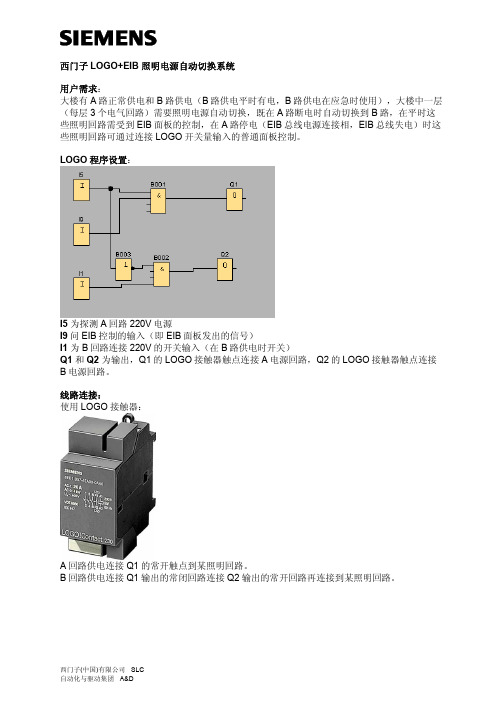
大楼有A路正常供电和B路供电(B路供电平时有电,B路供电在应急时使用),大楼中一层(每层3个电气回路)需要照明电源自动切换,既在A路断电时自动切换到B路,在平时这些照明回路需受到EIB面板的控制,在A路停电(EIB总线电源连接相,EIB总线失电)时这些照明回路可通过连接LOGO开关量输入的普通面板控制。
LOGO程序设置:
I5 为探测A回路220V电源
I9问EIB控制的输入(即EIB面板发出的信号)
I1 为B回路连接220V的开关输入(在B路供电时开关)
Q1 和Q2 为输出,Q1的LOGO接触器触点连接A电源回路,Q2的LOGO接触器触点连接B电源回路。
线路连接:
使用LOGO接触器:
A回路供电连接Q1的常开触点到某照明回路。
B回路供电连接Q1输出的常闭回路连接Q2输出的常开回路再连接到某照明回路。
所需设备:
名称型号数量人民币表价小计
LOGO主机6ED1052-1FB00-
0BA4
1 111
2 1112
LOGO 接触器6ED1057-4EA00-
0AA0
6 136 816
LOGO/EIB网关6BK1 700-0BA00-
0AA1
1 1597 1597
LOGO 24V 电源 6EP1331-1SH02 1 494 494
合计: 5823 小结:
利用LOGO强大的逻辑功能和具有同EIB网关的技术特色,可满足建筑用户对电源不间断供
应和在应急时灯光控制的任何需求。
eib系统介绍

KNX EIB 系统介绍前言电气安装总线随着人们对建筑品味的日益提高,人们在希望降低能源消耗的同时,对建筑物电气安装的灵活性、舒适性与功能性也提出了越来越高的要求,它有力的推进了建筑系统工程的发展。
建筑系统工程的基础是建筑安装技术的一体化,打破行业的界线,将智能化的家庭技术与楼宇技术的全部功能包揽于一身。
传统的电气安装技术已难以满足现代化建筑的需要,所谓智能化的建筑成为当今先进建筑的必然。
(北京锐志辉煌科技有限公司400-085-3338)早在20世纪80年代中期,各家公司就已不谋而合的酝酿着将总线技术应用于电气安装技术与楼宇技术,人们已经发现各个厂家专用系统的进入市场,给市场的相互广泛渗透设置了屏障。
在此背景下,发源于欧洲的EIB(European Installation Bus,欧洲安装总线)智能安装系统应运而生。
(北京锐志辉煌科技有限公司400-085-3338)1987年,德国几家知名的厂商发起成立EIB联盟,并于1990年成立EIBA (欧洲安装总线协会,现已改为KNX),协会创建了一个以EIB为核心的统一的智能楼宇控制技术的全球标准,这份标准保证不同生产厂商制成的各种元器件与系统能相互兼容和交互操作。
目前世界各地有近200家电器制造商在围绕EIB 产品进行研制、开发,不同厂家的EIB产品完全无缝兼容。
EIB系统不仅在德国、在欧洲而且在世界范围内也逐步的被认可、被接受。
(北京锐志辉煌科技有限公司400-085-3338)EIB是将目前计算机控制技术领域最新的现场总线技术应用于传统的电气安装领域的新技术,它使来自各行各业各工种的各个单独的产品和系统联合成为一个相互联通的系统,有效地实现了对照明、调光、百叶窗、场景控制、用电负荷控制、安保、供热系统等的智能控制,达到安全、节能、人性化的效果,并能在今后的使用中方便地根据用户的需求进行变更,成为真正灵活智能的电气安装系统。
它的优势是传统电气安装所无法比拟的。
eib智能照明系统原理
eib智能照明系统原理EIB智能照明系统原理EIB智能照明系统是一种基于EIB(欧洲安防系统总线)技术的智能照明控制系统。
该系统利用先进的通信技术和智能控制算法,实现对照明设备的集中控制和远程管理。
本文将从系统原理的角度,详细介绍EIB智能照明系统的工作原理和优势。
EIB智能照明系统的工作原理基于分布式控制理念。
系统中的每个照明设备都连接到总线上,并通过总线与其他设备进行通信和控制。
这样,可以实现对每个设备的个别控制,也可以将多个设备组合成一个照明场景,实现整体控制。
通过总线的通信,照明设备可以接收到来自中央控制器或其他设备的控制指令,并实时响应。
EIB智能照明系统采用了开放的通信协议和标准化的总线结构。
这使得系统具有高度的兼容性和扩展性。
不同品牌的照明设备可以通过EIB总线连接到同一个系统中,实现统一的控制。
同时,系统支持多种通信介质,如有线和无线通信,可以根据实际需求选择合适的通信方式。
此外,系统还支持远程管理和监控,通过互联网或手机应用程序可以实现对照明设备的远程控制和状态监测。
EIB智能照明系统具有智能控制和能效管理的特点。
系统中的照明设备可以根据环境的变化自动调整亮度和色温,以实现舒适的照明效果。
同时,系统还可以根据时间表或传感器的信号自动控制照明设备的开关,实现能耗的最优化。
例如,在无人的房间中,系统可以自动关闭照明设备,以节约能源。
此外,系统还可以通过能耗监测和分析,帮助用户了解和管理能源消耗情况,实现节能减排的目标。
EIB智能照明系统的应用范围广泛。
它可以应用于各种场所,如办公楼、商场、酒店、医院等。
无论是新建还是改造项目,都可以选用EIB智能照明系统来实现照明的智能控制和能效管理。
该系统还可以与其他建筑管理系统集成,实现更高级别的自动化和智能化。
EIB智能照明系统是一种基于EIB技术的智能照明控制系统,具有分布式控制、开放兼容、智能控制和能效管理等特点。
它可以提供个性化的照明控制方案,提高照明质量和能效,减少能源消耗。
EIB总线介绍
18
EIB软件ETS
ETS (EIB Tools Software) 由EIB协会EIBA统一销售,不受制于任何生产厂家 界面友好,易于操作 数据库由各厂家免费提供 软件使用方法:
2、多功能集成
– 照明控制:开/关,调光,设定照度 – 窗帘/百叶窗控制 – 通风、空调、供热 – 能源和负荷控制 – 远程控制和集中监控 EIB产品可方便的实现以上功能的集成
6
3、安全性,可靠性
– EIB开关是低压总线电源供电,DC24V,安全可靠 – EIB由市场引导技术,可靠始终放在第一位 – 经过十几年发展,已形成可靠的系列产品 – 清华同方调查结论:EIB标准最符合中国的国情和应用条件
15
EIB拓朴结构
PS/CH
EIB系统分为线路和区域 两部分,大大增强了系 统功能的可靠性
LR-线路中继器,LC-线 路耦合器,BC-总线耦 合器,PS/CH-电源
BC、LC、LR为同一元 件,只是download不同 的程序
BC、LC带过滤表,相 当于gateway的功能
区域
BC
区域
PS/CH
LC
LC
LC
PS/CH
PS/CH
BC
环型 星型 ห้องสมุดไป่ตู้状
16
EIB拓朴结构
区域干线
主线路
1
LC
1 2 3
255
线路
BC
西门子设计说明书
B座智能照明设计说明书采用先进的EIB智能控制系统实现空间照明智能管理,作为最有效的节能措施,EIB在本工程中的具体应用如下:一、地下室控制区域1.车道(AL-RF-1、2;ALE-RF-1、2;AL-D2-1、2、3;ALE-D2-1、2、3;AL-D1-1、2、3;ALE-D1-1、2、3)该区域设置了西门子的手动智能控制面板,可以对车库出入口、车行道和停车位照明进行分区的手动控制。
EIB系统可以根据上下班时间段,设置时间表自动运行车道灯光的开闭控制。
例如:工作日早九点至十点灯光全部开启,下午四点至六点灯光全部开启,其他时间段灯光只保留一半开启。
休息日灯光只开启一半,夜间可考虑被控灯光全部关闭,由于部分应急照明不在被控范围内,所以夜间的车库照明在EIB控制部分关闭的情况下依然可以保持定的照度,安防监控照明也得到基本照度保障。
通过始终控制在方便人员管理的同时,节约照明耗电。
考虑到日光灯的频繁启动会大大影响灯具寿命,所以不推荐在车道区域或者车库出入口位置安放探测器。
2.柴油机房(ALE-YJ1、YJ2)该区域设置了西门子的手动智能控制面板,该区域的灯光管理可以根据需要定义全部或者部分回路被控,以增强使用者的控制灵活性。
3.室外(AL-SW、FGM-A、FGM-B)通过西门子的手动智能控制面板,可以根据不同要求做出不同的夜景照明组合。
根据节假日性质不同,可以分为平时晚间,周末,一般节日和重要节日几个不同的等级,利用方便的时钟设定,作出时间控制表,使全年的夜景照明控制自动运行。
4.楼梯间和电梯前室楼梯间照明采用声光控制单元,在采光情况合适的情况下根据周围环境的噪音判断控制灯光开启,最长可设置3分钟延时关闭灯光。
电梯前室通过定时方式设定上下班时间段控制每个回路的启停。
5.卫生间(AL-D2-1、AL-RF-1)地下部分的卫生间采用人体红外探测和声控相结合的逻辑判断模式进行控制。
当人体红外或声控探测器探测到人员存在时,卫生间照明打开。
西门子instabus KNXEIB系统
希思罗(Heathrow)国际机场数字照明设计方案英国希思罗(Heathrow)国际机场,是世界最大的机场之一。
其T5航站楼工程总投资金额42亿英磅,是现今英国最大的基础建筑项目,主体包括一座核心候机楼与两个用高速链路相连接的卫星楼。
航站楼的主候机楼,两个卫星楼,公共通道、电梯前室以及交通中心候车、停车、公共卫生间等公共部位照明以及广告、标识装饰等照明,均采用西门子instabus KNX/EIB系统实现照明控制。
系统简介1.西门子instabus KNX/EIB系统KNX是一个分布式现场总线标准,其拓扑结构包括:线路(Line)、区域(Area)以及系统(System)。
线路(Line)是最小的组成单元,每条线路最多64个设备,每个区域(Area)最多15条线路,而每个系统最多15个区域。
随着网络技术和局域网(LAN)的普及,KNX标准中提出了EIBnet/IP的概念,通过EIBnet/IP协议,KNX总线可以直接与TCP/IP系统连接,总线信号可以在高速以太网上传输。
EIBnet/IP协议的出现,使得系统的扩展不再受传输距离的影响,而数据的传输量和传输速度也不再成为KNX系统的问题。
西门子instabus KNX/EIB系统是基于KNX标准的全分布总线系统,最大的优点在于其控制的灵活、功能的强大及系统的可塑性。
选择不同的模块化设备,通过积木式的不同组合就可以实现各种功能控制,同时挂在总线上的设备运行相互独立,系统的改造和扩展就变得非常容易了。
2.DALI数字可寻址灯光接口现代建筑照明中,荧光灯的使用相当普及。
随着人们对光环境要求的提高,荧光灯的控制也从简单的开关发展到亮度的调节,而荧光灯调光控制方法又取决于电子镇流器技术。
于是从1984年Philips首先推出第一个商业系列电子镇流器以来,电子镇流器的技术获得了飞速的发展。
从1-10V模拟量接口电子镇流器,到数字信号接口(DSI)电子镇流器,以及最新的DALI数字式可寻址灯光接口镇流器,荧光灯的调光方式已完成了模拟量控制向数字化控制的飞跃。
instabuseib系统简介 (1)
instabus EIB系统简介1. 概述西门子instabus是一个基于事件控制的分布式总线系统。
它是随着楼宇管理系统对于灵活方便智能化的电气安装,以及低能耗的需求而发展起来的。
它所使用的总线技术称为EIB(European Installation Bus)。
众多制造厂商联合起来成立了一个组织称为EIBA(European Installation Bus Association)。
EIBA成员保证其产品符合协议,以实现各厂商生产的装置可相互兼容。
2. 功能及典型应用•灯光照明及管理•空调、供暖、通风控制及管理(HV AC)•电器控制:包括电动门、窗帘、投影机、投影屏等电器•自动喷灌溉及给排水控制•大型设备状态监控•安防报警3. 优点简捷——布线的简化使得费用和火灾风险大为降低。
经济——重新设置参数代替了重新安装,系统容易修改和扩展。
协调——控制,执行,保护,安装装置的相互联接替代了各个独立的单一系统。
实用——项目设计,现场调试和错误诊断均由运行于PC的工具软件支持。
便于安装——部件均采用模块化设计,减少布线需要。
向上兼容——可与上一级楼宇控制系统(如Honeywell),公共电话网ISDN及Profibus等通讯。
4. 总线拓扑结构线路(Line)——系统基本单位,每条线路最多可挂64个总线装置。
区域(Zone)——最多12条线路,通过连在总线路(Mainline)上的线路耦合器形成一个区域。
独立系统——最多15个区域各通过联接区域线路(Backbone)上的区域耦合器形成独立系统。
综合系统——独立系统还可通过连在区域线路上的网关(Gateway)与另外的EIB系统或外部系统(Honeywell),ISDN,Profibus等相连。
5. 控制方式Instabus EIB主要包括以下控制方式:1. 按键开关就地控制与传统开关控制相同,每组按键对应控制一条设计的回路,按键上具有位置、状态LED灯光指示及功能图案指示(如照明、风扇、窗帘、调光等),使用时一目了然,极其方便。
- 1、下载文档前请自行甄别文档内容的完整性,平台不提供额外的编辑、内容补充、找答案等附加服务。
- 2、"仅部分预览"的文档,不可在线预览部分如存在完整性等问题,可反馈申请退款(可完整预览的文档不适用该条件!)。
- 3、如文档侵犯您的权益,请联系客服反馈,我们会尽快为您处理(人工客服工作时间:9:00-18:30)。
KNX EIB系统介绍 系统功能说明 系统产品介绍 产品应用介绍 典型应用介绍
Angela - SLC A&D LV/ET/BC PM Slide 9
KNX EIB功能说明
Siemens 成就工业,建筑未来 instabus KNX EIB Protection & Control, 西门子楼宇智能控制统 From Industry To Construction
多种传输媒介 • 双绞线 (TP) • 电力线 (PL) • 无线电波(RF)
Angela - SLC A&D LV/ET/BC PM Slide 4
KNX EIB系统应用领域
Siemens 成就工业,建筑未来 instabus KNX EIB Protection & Control, 西门子楼宇智能控制统 From Industry To Construction
Angela - SLC A&D LV/ET/BC PM Slide 2
西门子楼宇智能控制系统
Siemens 成就工业,建筑未来 instabus KNX EIB Protection & Control, 西门子楼宇智能控制统 From Industry To Construction
KNX EIB系统介绍 系统功能说明 系统产品介绍 产品应用介绍 典型案列介绍
KNX EIB系统介绍 系统功能说明 系统产品介绍 产品应用介绍 典型案列介绍
线路 Line :最多64 个设备 ••线路 Line :最多64 个设备 区域 Area :最多15条线路 ••区域 Area :最多15条线路 系统System:最多15个区域 ••系统System:最多15个区域
Angela - SLC A&D LV/ET/BC PM Slide 7
最多64个DALI调光整流器 最多16个通道 最多16个场景 最多300米总线 应用于灯光控制
Angela - SLC A&D LV/ET/BC PM Slide 12
室内环境控制
Siemens 成就工业,建筑未来 instabus KNX EIB Protection & Control, 西门子楼宇智能控制统 From Industry To Construction
在开始阶段,有很多功能强,价格合 理的产品可选择,节省时间。
网关
EIB连接技术的领导者,在市场上拥有最广泛 的连接以太网产品。 IP连接设备的价格具有优势。 最广泛的网关产品
在开始阶段,有很多能强,价格合理 的产品可选择,节省时间。
遮阳控制系统 系统产品 线路控制和自控设 备
在非民用建筑中,具有丰富的产品和应用经验
ET New Product Road Show
—— GAMMA Instabus KNX EIB
Ye Min Li ( Angela )
Instabus Product Manager Tel: ( +86 ) 21 58882000-2654 E-mail: minli.ye@
使用数据轨道节省时间和费用
轨道安装设备
通过数据导轨无需连接器就可实现安全的 总线连接。
节省空间和费用
显示单元和操作面 板
集成移动探测器的多功能控制面板
因为不需要两个单独的设备(控制面 板和移动探测器),所以省钱、省空 间而且设计更完美 无需工程师手动调节控制参数 无需具备控制技术知识
集成自适应室内温度控制器的多功能控制 面板 控制面板UP588 ETS软件调试 控制面板UP588 用户可定义和存储场景、周序续 1-4极的控制面板可以安插在齐平安装的 驱动器上 竞争对手不能提供带AST的可插装控制 面板的齐平安装驱动器
比使用特殊工具更快更方便
无需安装工程师的帮助
带AST齐平安装驱 动技术
省钱,省空间和省时间
Angela - SLC A&D LV/ET/BC PM Slide 16
KNX EIB 产品介绍
感应器 DELTA style DELTA miro 驱动器 DELTA ambiente
Siemens 成就工业,建筑未来 instabus KNX EIB Protection & Control, 西门子楼宇智能控制统 From Industry To Construction
Siemens 成就工业,建筑未来 instabus KNX EIB Protection & Control, 西门子楼宇智能控制统 From Industry To Construction
KNX EIB系统介绍 系统功能说明 系统产品介绍 产品应用介绍 典型案列介绍
220V AC
控制面板
温度控制
KNX EIB系统介绍 系统功能说明 系统产品介绍 产品应用介绍 典型案列介绍
KNX EIB系统介绍 系统功能说明 系统产品介绍 产品应用介绍 典型应用介绍
Angela - SLC A&D LV/ET/BC PM Slide 14
KNX EIB 产品介绍
竞争优势概述
主题
KNX EIB系统介绍 系统功能说明 系统产品介绍 产品应用介绍 典型案列介绍
移动感应
Data network
RF
RF
集中控制
Angela - SLC A&D LV/ET/BC PM Slide 6
KNX EIB系统拓扑结构
Siemens 成就工业,建筑未来 instabus KNX EIB Protection & Control, 西门子楼宇智能控制统 From Industry To Construction
Siemens 成就工业,建筑未来 instabus KNX EIB Protection & Control, 西门子楼宇智能控制统 From Industry To Construction
KNX EIB系统介绍 系统功能说明 系统产品介绍 产品应用介绍 典型案列介绍
超过 50 000 设备 超过32 000 组 无限制的场景模式 最多180 000米总线 广泛的应用领域
KNX EIB系统介绍 系统功能说明 系统产品介绍 产品应用介绍 典型案列介绍
Integration of single applications
灯光控制 遮阳控制
取暖和空调设备控制
能源负载管理 操作和监控
Angela - SLC A&D LV/ET/BC PM Slide 10
灯光、遮阳控制功能
Siemens 成就工业,建筑未来 instabus KNX EIB Protection & Control, 西门子楼宇智能控制统 From Industry To Construction
产品优势
客户利益
灯光控制系统
在非民用建筑领域里,具有很多独特的产品和 应用经验 EIB-DALI连接技术的领导者
KNX EIB系统线路说明
Siemens 成就工业,建筑未来 instabus KNX EIB Protection & Control, 西门子楼宇智能控制统 From Industry To Construction
KNX EIB系统介绍 系统功能说明 系统产品介绍 产品应用介绍 典型案列介绍
灯光控制 • 开关 • 调光 遮阳控制 • 百叶,风力,雨 水等环境状况自动控制。
电源线
KNX EIB系统介绍 系统功能说明 系统产品介绍 产品应用介绍 典型案列介绍
EIB总线
场景控制 • 多功能控制面板或者触摸 屏上的一个按键实现预先 设定的灯光亮度,窗帘位 置等,已适应各种应用场 合,营造不同的环境围。
Siemens 成就工业,建筑未来 instabus KNX EIB 竞争优势概述 Protection & Control, 西门子楼宇智能控制统 From Industry To 主题 Construction
KNX EIB系统介绍 系统功能说明 系统产品介绍 产品应用介绍 典型案列介绍
客户利益
有很多设备可供选择
线路耦合单元,只有1个模数
最小的安装空间需求
多样且高性能的产品
在开始阶段,有很多能强,价格合理 的产品可选择,节省时间。
Angela - SLC A&D LV/ET/BC PM Slide 15
KNX EIB 产品介绍
产品优势
所有新的轨道安装设备都有总线端子和连 到总线连接器的接触系统
KNX EIB系统介绍 系统功能说明 系统产品介绍 产品应用介绍 典型案列介绍
Hotel 酒店
Airport 机场
Resident 住宅
Office 办公 Arena 运动
Angela - SLC A&D LV/ET/BC PM Slide 5
KNX EIB系统结构示意图
照明 通风 遮阳 安防 能源管理
KNX EIB系统介绍 系统功能说明 系统产品介绍 产品应用介绍 典型案例介绍
Angela - SLC A&D LV/ET/BC PM Slide 3
KNX EIB系统特点
开放的标准 KNX EIB • 统一的EIB标准 • 不同厂商的产品, 在同一界 面下集成 各单独功能的集成 • 照明 • 遮阳 • 采暖 • 能源控制 • 集中管理
KNX EIB系统介绍 系统功能说明 系统产品介绍 产品应用介绍 典型案列介绍
双值输入
开关执行器
调光器
Angela - SLC A&D LV/ET/BC PM Slide 17
KNX EIB 产品介绍
系统设备 总线耦合器 功能模块 系统电源 线路耦合器