MAX6309UK27D2-T中文资料
SLMC 数显流量开关集成型说明书 - PF2M7##系列

Instruction ManualPF2M7## seriesThe intended use of the digital flow switch is to monitor and display flow information.These safety instructions are intended to prevent hazardous situations and/or equipment damage. These instructions indicate the level of potential hazard with the labels of “Caution,” “Warning” or “Danger.”They are all important notes for safety and must be followed in addition to International Standards (ISO/IEC) *1), and other safety regulations. *1)ISO 4414: Pneumatic fluid power - General rules relating to systems. ISO 4413: Hydraulic fluid power - General rules relating to systems.IEC 60204-1: Safety of machinery - Electrical equipment of machines. (Part 1: General requirements)ISO 10218-1: Manipulating industrial robots -Safety. etc.∙ Refer to product catalogue, Operation Manual and Handling Precautions for SMC Products for additional information. ∙ Keep this manual in a safe place for future reference.∙ This product is class A equipment intended for use in an industrial environment. There may be potential difficulties in ensuring electromagnetic compatibility in other environments due to conducted or radiated disturbances.CautionCaution indicates a hazard with a low level of risk which, ifnot avoided, could result in minor or moderate injury.WarningWarning indicates a hazard with a medium level of riskwhich, if not avoided, could result in death or serious injury.DangerDanger indicates a hazard with a high level of risk which, ifnot avoided, will result in death or serious injury.Warning∙ Always ensure compliance with relevant safety laws and standards.∙ All work must be carried out in a safe manner by a qualified person in compliance with applicable national regulations.∙ Do not disassemble, modify (including changing the printed circuit board) or repair. An injury or failure can result.∙ Do not operate the product outside of the specifications. Fire, malfunction or damage to the product can result.∙ Do not operate in an atmosphere containing flammable, explosive or corrosive gas.Fire or an explosion can result.∙ Do not use the product for flammable fluids. Fire, explosion, damage or corrosion can result. ∙ If using the product in an interlocking circuit:Provide a double interlocking system, for example a mechanical system.∙ Check the product for correct operation.Otherwise malfunction can result, causing an accident.∙ Do not use the product in a place where static electricity is a problem.Product failure or system malfunction may result.Otherwise electric shock, malfunction or product damage can result. ∙ Refer to the operation manual on the SMC website (URL: https:// ) for more safety instructions.2 SpecificationsWarningSpecial products (-X) might have specifications different from those shown in this section. Contact SMC for specific drawings.3.1 PF2M7## (with flow adjustment valve)ItemDescriptionSocket Socket for electrical connections.Piping port Connected to the fluid inlet IN side and to the fluid outlet OUT side.Flow adjustment valve Orifice mechanism to adjust the flow. Lock ring Used to lock the flow adjustment valve.Mounting hole Used to mount the product on a DIN rail or directly to a panel.BodyThe body of the product.Lead wire and connector Lead wire to supply power and output signals.3.2 DisplayItem DescriptionUP buttonSelects the mode or increases the ON/OFF set value. Press this button to change to the peak display mode.DOWN button Selects the mode or decreases the ON/OFF set value.Press this button to change to the bottom displaymode.Main displayDisplays the flow value, setting mode, and error indication.Four display modes can be selected: display always in red or green, or display changing from green to red, or red to green, according to the output status (OUT1). SET button Press this button to change to another mode and to set a value.Output display (Operation LED) Displays the output status of OUT1 and OUT2. OUT1: LED is ON (Orange) when the output is ON. OUT2: LED is ON (Orange) when the output is ON. When the accumulated pulse output mode is selected, the output display is OFF.Units display Arbitrary units are ON based on the flow display setting (instantaneous or accumulated flow)IO-Link status indicator light LED is ON when OUT1 is used in IO-Link mode. (LED is OFF in SIO mode)ORIGINAL INSTRUCTIONSModel 701 702 705 710 725 750 711 721 F l u i dApplicable fluidDry air, N 2, Ar, CO 2(ISO8573-1 1.1.2 to 1.6.2)Fluid temperature range 0 to 50 o CF l o w r a t e Detection method Thermal(main flow) Thermal (branch flow) R a t e d f l o w r a n g e [L /m i n ] Dry air,N 2,Ar 0.01 to 1 0.02 to 2 0.05 to 5 0.1 to 10 0.3 to 25 0.5 to 50 1 to 100 2 to200CO 20.01 to 0.5 0.02 to 1 0.05 to 2.5 0.1 to 5 0.3 to 12.5 0.5 to 25 1 to 50 2 to100S e t f l o w r a n g e Instantaneous flow [L/min]-0.05 to 1.05 -0.1 to 2.1 -0.25 to 5.25 -0.5 to 10.5 -1.3 to 26.3 -2.5 to 52.5 -5 to 105 -10 to 210Accumulated flow [L] 0.00 to 9999999.99 0.0 to 99999999.9 0 to 999999999 M i n . s e t t i n g u n i t Instantaneous flow [L/min] 0.001 0.01 0.1 1Accumulatedflow [L]0.01 0.1 1 Accumulatedvolume [L/pulse]0.01 0.1 1 Accumulated value hold Select from 2 and 5 minutesP r e s s u r eOperating pressure range-0.1 to 0.75 MPa Rated pressurerange-0.07 to 0.75 MPaProof pressure 1.0 MPa Pressure loss Refer to the pressure loss graph. Pressure characteristics ±5%F.S. ±1 digit (0.35 MPa standard)E l e c t r i c a l P o w e r s u p p l y v o l t a g e Switch output device 12 to 24 VDC ±10% IO-Link device18 to 30 VDC ±10% Currentconsumption 35 mA or less ProtectionPolarity protection A c c u r a c yDisplay accuracy ±3% F.S. ±1 digitAnalogue output accuracy ±3% F.S.Repeatability ±1%F.S. ±1 digit(±2% F.S. ±1 digit when digital filter is set to 0.05 s) Temperature characteristics ±3%F.S. ±1 digit (15 to 35 oC: 25 oC standard) ±5%F.S. ±1 digit (0 to 50 o C: 25 o C standard) S w i t c h o u t p u tOutput type NPN or PNP open collectorOutput mode Select from hysteresis mode, window comparator mode, accumulated output mode, accumulated pulse output mode, error outputand switch output OFFSwitch operation Select from normal output and reversed outputMaximum load current80 mA Maximum applied voltage 28 VDC (NPN only)I n t e r n a l v o l t a g e d r o pStandard valueNPN: 1 V or less (Load current 80 mA) PNP: 1.5 V or less (Load current 80 mA) IO-Link compatible product 1.5 V or less (Load current 80 mA) Response time 50 ms or lessDelay time 0 to 0.10 s (0.01 s increment), 0.1 to 1.0 s (0.1 s increment), 1 to 10 s (1 s increment)Select from 20 s, 30 s, 40 s, 50 s, 60 sHysteresis VariableProtectionShort circuit protectionModel 701 702 705 710 725 750 711 721 A n a l o g u e o u t p u tOutput type Voltage output: 1 to 5 V (or 0 to 10 V),Current output 4 to 20 mAI m p e d a n c e Voltage outputOutput impedance approx.1 kΩ CurrentoutputMax. load impedance Power supply voltage 24 V: 600 Ω Power supply voltage 12 V: 300 Ω Response time 50 ms ±40% D i s p l a yReference conditionSelect from normal condition (NOR) andstandard condition (STD) Display mode Select from instantaneous flow andaccumulated flow U n i t InstantaneousflowL/min, cfm Accumulated flowL, ft 3 D i s p l a y a b l e r a n g e Instantaneous flow [L/min]-0.05 to 1.05 -0.1 to 2.1 -0.25 to 5.25 -0.5 to 10.5 -1.3 to 26.3 -2.5 to 52.5 -5 to 105 -10 to 210 Zero cut-off range 0 to ±10%F.S. (selected for every 1%F.S. of max. rated flow rate) Accumulated flow [L] 0.00 to 9999999.99 0.0 to99999999.9 0 to 999999999Display Display type: LCD, Display colour: Red, green,Display digit: 7-segment, 4 digits Operation LED LED is ON when switch output is ON,OUT1/OUT2: Orange Digital filterSelect from 0.05 s, 0.1 s, 0.5 s, 1 s, 2 s and 5 s E n v i r o n m e n t a l r e s i s t a n c eEnclosure IP40 Withstand voltage 1000 VAC, 1 min. between terminals andhousing Insulation resistance 50 MΩ or longer (with 500 VDC) between terminals and housing Operatingtemperature rangeOperation: 0 to 50 o C, Storage: -10 to 60 o C(no freezing or condensation)Operating humidity range Operation, Storage: 35 to 85%R.H. (no freezing or condensation) P i p i n gP i p i n g s p e c i f i c a t i o n One-touch fitting C4 (ϕ4) / C6 (ϕ6)C6 (ϕ6) / N7 (ϕ1/4”) C8 (ϕ8) / N7 (ϕ1/4”)Screw fitting (Rc/NPT/G) 01 (Rc1/8) N1 (NPT1/8) F1 (G1/8)02 (Rc1/4) N2 (NPT1/4) F2 (G1/4)Port direction Straight, RearMaterial fluid contact parts PPS, PBT, FKM, SUS304, brass (electrolessnickel plating), Si, Au, GE4FW e i g h tB o d y One-touch fitting Straight: 40 g Rear: 55 g 48 g 63 g Screw fittingStraight: 60 g Rear: 75 g 72 g 87 gFlow adjustment valve -+34 g Lead wire +35 g Bracket +20 g Panel mount adapter +15 g DIN rail mounting bracket +65 gThe product code is displayed for approximately 3 seconds afterpower is supplied.Then measurement mode will be displayed and the switchoperation will start.4.1 InstallationWarning∙Do not install the product unless the safety instructions have been readand understood.∙Use the product within the specified operating pressure andtemperature range.∙Proof pressure could vary according to the fluid temperature. Checkthe characteristics data for operating pressure and proof pressure.4.2 EnvironmentWarning∙Do not use in an environment where corrosive gases, chemicals, saltwater or steam are present.∙Do not use in an explosive atmosphere.∙Do not expose to direct sunlight. Use a suitable protective cover.∙Do not install in a location subject to vibration or impact in excess ofthe product’s specifications.∙Do not mount in a location exposed to radiant heat that would result intemperatures in excess of the product’s specifications.∙Refer to the flow direction of the fluid indicated on the product forinstallation and piping.∙Do not mount the body with the bottom facing upwards.Retention of air can cause inability to measure accurately.∙Do not insert metal wires or other foreign matter into the piping port.This can damage the sensor causing failure or malfunction.∙Never mount a product in a location that will be used as a foothold.The product may be damaged if excessive force is applied by steppingor climbing onto it.∙If there is a risk of foreign matter entering the fluid, install and pipe afilter or mist separator at the inlet to avoid failure and malfunction.Otherwise damage or malfunction can result.4.3 Panel mounting∙Insert panel mount adapter B (supplied as an accessory) into sectionA of the panel mount adapter.Push panel mount adapter B from behind until the display is fixed ontothe panel.The bracket pin engages the notched part of panel adapter section Cto fix the display.∙The switch can be mounted on a panel with a thickness of 1 to 3.2 mm.4.4 Bracket mounting∙Mount the bracket using the mounting screws supplied.∙The required tightening torque is 0.42 ±0.04 N•m.∙Install the product (with bracket) using the M3 screws (4 pcs.).∙Bracket thickness is approximately 1.2 mm.4.5 DIN rail mounting (using ZS-33-R#)∙Mount the DIN rail mounting parts using the mounting screws and jointscrews supplied.∙The required tightening torque of the DIN rail mounting screws and∙Refer to the operation manual on the SMC website(URL: https://) for all mounting dimensions.4.6 PipingCaution∙Before connecting piping make sure to clean up chips, cutting oil, dust etc.∙Ensure there is no leakage after piping.∙Any dust left in the piping should be flushed out by air blow beforeconnecting piping to the product.Otherwise damage or malfunction can result.∙For piping of the product, hold the piping with a wrench on the metalpart of the product.Holding other parts of the product with a wrench may damage the product.4.7 WiringCaution∙Do not perform wiring while the power is on.∙Confirm proper insulation of wiring.∙Do not route wires and cables together with power or high voltage cables.Otherwise the product can malfunction due to interference of noise andsurge voltage from power and high voltage cables to the signal line.∙Keep wiring as short as possible to prevent interference fromelectromagnetic noise and surge voltage. Do not use a cable longerthan 30 m. When using it as an IO-Link device, do not use a cablelonger than 20 m.∙Ensure that the FG terminal is connected to ground when using acommercially available switch-mode power supply.∙When the analogue output is used, install a noise filter (line noise filter,ferrite element, etc.) between the switch-mode power supply and thisproduct.Connecting / Disconnecting∙When mounting the connector, insert it straight into the socket, holdingthe lever and connector body, and push the connector until the leverhooks into the housing, and locks.∙When removing the connector, press down the lever to release thehook from the housing and pull the connector straight out.Connector pin numbers (on the lead wire)•Lead wire and connector (ZS-33-D)No. Signal name Lead wire colour1 DC(+) Brown2 OUT2 White3 OUT1 Black4 DC(-) Blue•M12 conversion lead wire (ZS-33-DM)Used as switch output deviceNo. Signal name Lead wire colour1 DC(+) Brown2 N.C./OUT2 White3 DC(-) Blue4 OUT1 BlackUsed as IO-Link deviceNo. Signal name Lead wire colour1 L+Brown2 N.C./OUT2 White3 L-Blue4 C/Q BlackPower is supplied*: The outputs will continue to operate during setting.*: Simple setting mode and function selection mode settings arereflected each other.6 Flow Setting6.1 Switch operationWhen the flow exceeds the set value, the switch will be turned ON.When the flow falls below the set value by the amount of hysteresis ormore, the switch will be turned OFF.The default setting is to turn on the flow switch when the flow reaches thecentre of the upper limit of the rated flow range.If the operation shown below is acceptable, keep this setting.*: For hysteresis refer to [F 1] Setting of OUT1 and [F 2] Setting of OUT2.Without flow adjustmentvalve (using ZS-33-M)With flow adjustment valve(using ZS-33-MS)Press the SETbutton for 5seconds or longerPress the SETbutton between2 to 5 secondsPress the SETbutton onceFlow Setting andHysteresis(Simple settingmode)Function Setting(Functionselection mode)Other Settings∙Snap shot∙Key-lock∙Zero clear[Simple setting mode (Hysteresis mode)]In the Simple setting mode, the set value and hysteresis can be changed. (1) Press the SET button once in measurement mode.[P_1] or [n_1] and the [current set value] are displayed alternately.(2) Change the set value using the UP or DOWN button and press theSET button to set the value. Then, the setting moves to hysteresis setting (The snap shot function can be used). ∙ Press the UP button continuously to keep increasing the set value.∙ Press the DOWN button continuously to keep decreasing the set value.(3) [H_1] and the current set value are displayed in turn.(4) Change the hysteresis by pressing the UP or DOWN button and press the SET button. Setting is completed and the product returns to measurement mode (The snap shot function can be used).* For models with switch outputs for both OUT1 and OUT2, [P_2] or [n_2] will be displayed. These are set simultaneously.* After enabling the setting by pressing the SET button, it is possible to return to measurement mode by pressing the SET button for 2 seconds or longer.* When hysteresis mode is not used, "Input set value” is displayed. * The set value and hysteresis settings limit each other.* For more detailed setting, set each function in function selection mode.8.1 Function selection modeIn measurement mode, press the SET button for 2 to 5 seconds to display [F 0] on the display.Select to display the function to be change [F ].Press the SET button for 2 seconds or longer in function selection mode to return to measurement mode. *: Some products do not have all the functions. If a function is not available or selected due to configuration of other functions, [- - -] is displayed.8.2 Default settings*: Setting is only possible for models with the units selection function. *: Only available for models with switch outputs for both OUT1 and OUT2.*: This function is available for models with analogue output. Analogue free span function can be selected.*: This function is available in IO-Link compatible products. *: This function is available for models with external input.9 Other Settings∙ Snap shot function∙ Peak/bottom value indication ∙ Reset∙ Key-lock function ∙Zero clear functionRefer to the operation manual on the SMC website(URL: https:// ) for setting these functions.10.1 General MaintenanceCaution∙ Not following proper maintenance procedures could cause the product to malfunction and lead to equipment damage.∙ If handled improperly, compressed air can be dangerous.∙ Maintenance of pneumatic systems should be performed only by qualified personnel.∙ Before performing maintenance, turn off the power supply and be sure to cut off the supply pressure. Confirm that the air is released to atmosphere.∙ After installation and maintenance, apply operating pressure and power to the equipment and perform appropriate functional and leakage tests to make sure the equipment is installed correctly.∙ If any electrical connections are disturbed during maintenance, ensure they are reconnected correctly and safety checks are carried out as required to ensure continued compliance with applicable national regulations.∙ Do not make any modification to the product.∙ Do not disassemble the product, unless required by installation or maintenance instructions.∙ How to reset the product after a power cut or when the power has been unexpectedly removedThe settings of the product are retained from before the power cut or de-energizing.The output condition also recovers to that before the power cut or de-energizing, but may change depending on the operating environment. Therefore, check the safety of the whole system before operating the product.11 How to OrderRefer to drawings/catalogue on the SMC website (URL: https:// ) for ‘How to Order’ information.12 Outline Dimensions (mm)Refer to the operation manual on the SMC website(URL: https:// ) for outline dimensions.ItemDefault setting[F 0] [FLU] [FLU] Select the flow rate[Air] Dry air, N 2[rEF] Setting the unitscriteria [Std] Standard condition [Unit] Measurement unitsetting [ L] L/min (L) [norP] Switch output PNP/NPN setting [PnP] PNP output [i_o] SW / external input setting[oUt] SW output [F 1] [oUt1][oUt1] Setting of OUT1[HYS] Hysteresis mode[1ot] OUT1 outputconfiguration setting [1_P] Normal output[P_1] Set value [ ] 50% of maximum rated flow PF2M701: 0.5 L/min, PF2M702: 1.0 L/minPF2M705: 2.5 L/min, PF2M710: 5 L/minPF2M725: 12.5 L/min, PF2M750: 25 L/minPF2M711: 50 L/min PF2M721: 100 L/min[H_1] Hysteresis [ ] 5% of maximum rated flow PF2M701: 0.05 L/min,PF2M702: 0.1 L/minPF2M705: 0.25 L/min,PF2M710: 0.5 L/min PF2M725: 1.3 L/min, PF2M750: 2.5 L/minPF2M711: 5 L/min PF2M721: 10 L/min[dt1] Delay time setting [0.00] 0.00 s [CoL] Display colour setting [1SoG] ON: Green OFF: Red[F 2][oUt2][oUt2] Setting of OUT2[HYS] Hysteresis mode[2ot] OUT2 outputconfiguration setting [2_P] Normal output[P_2] Set value [ ] 50% of maximum rated flow PF2M701: 0.5 L/min,PF2M702: 1.0 L/min PF2M705: 2.5 L/min,PF2M710: 5 L/min PF2M725: 12.5 L/min,PF2M750: 25 L/minPF2M711: 50 L/minPF2M721: 100 L/min [H_2] Hysteresis [ ] 5% of maximum rated flow PF2M701: 0.05 L/min,PF2M702: 0.1 L/min PF2M705: 0.25 L/min,PF2M710: 0.5 L/min PF2M725: 1.3 L/min,PF2M750: 2.5 L/minPF2M711: 5 L/minPF2M721: 10 L/min [dt2] Delay time setting [0.00] 0.00 s [CoL] Display colour setting[1SoG] ON: Green OFF: Red[F 3] [FiL] [FiL] Digital filter setting [1.0] 1.0 s [F 4] [PrS] [PrS] Auto-preset function setting [oFF] Manual Item Default setting[F10] [FLo] [FLo] Display mode [inS] Instantaneous flow [F11] [drE] [drE] Display resolutionsetting [1000] 1000-split [F13] [rEv] [rEv] Reverse display[oFF] Not reverse[F14] [CUt] [CUt] Zero cut-off setting[1.0] 1% of maximum rated flow PF2M701: 0.01 L/min, PF2M702: 0.02 L/min PF2M705: 0.05 L/min, PF2M710: 0.1 L/min PF2M725: 0.3 L/min, PF2M750: 0.5 L/min PF2M711: 1 L/min PF2M721: 2 L/min[F20] [inP] [inP] External input setting [rAC] Accumulated value reset[F22] [AoUt] [AoUt] Analogue output setting [1-5] 1 to 5 V Voltage output(when voltage is output) [---] Analogue output is notselectable(for current type output)[F30] [SAvE] [SAvE] Accumulated flowvalue hold setting[oFF] Not held [F80] [diSP] [diSP] Display OFF modesetting[ on] Normal display [F81][Pin] [Pin] Security code [oFF] Unused[F90] [ALL][ALL] Setting of allfunctions[oFF] Unused[F96] [S_in][S_in] External input signalcheck No setting due to input signal setting[F98][tESt] [tESt] Output checking[ n] Normal output [F99] [ini][ini] Reset to the defaultsettings[oFF] Not recover13.1 Error indicationIf the error cannot be reset after the above measures are taken, or errors other than above are displayed, please contact SMC.Refer to the operation manual on the SMC website (URL: https://) for more detailed information about troubleshooting. 14.1 Limited warranty and Disclaimer/Compliance RequirementsRefer to Handling Precautions for SMC Products.15 Product disposalThis product should not be disposed of as municipal waste. Check yourlocal regulations and guidelines to dispose this product correctly, in orderto reduce the impact on human health and the environment.16 ContactsRefer to or www.smc.eu for contacts.URL: https:// (Global) https://www.smc.eu (Europe)SMC Corporation, 4-14-1, Sotokanda, Chiyoda-ku, Tokyo 101-0021, JapanSpecifications are subject to change without prior notice from the manufacturer.© 2021SMC Corporation All Rights Reserved.Template DKP50047-F-085M。
JUMO设备型号说明书
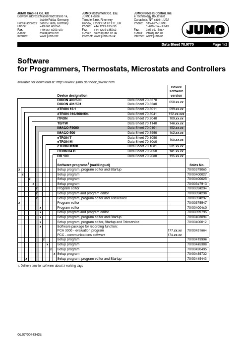
Page 2/2
Accessories for Programmers, Thermostats, Microstats and Controllers
Device designation
DICON 400/500 DICON 401/501
Data Sheet 70.3570 Data Sheet 70.3580
Software programs1 (multilingual)
x
Setup program, program editor and Startup
x
Setup program
x
Setup program
x
Setup program
x
Program editor
x
Setup program and program editor
e-mail:
mail@
Internet:
JUMO Instrument Co. Ltd. JUMO House Temple Bank, Riverway Harlow, Essex CM 20 2TT, UK Phone: +44 1279 635533 Fax: +44 1279 635262 e-mail: sales@ Internet:
eTRON T eTRON M
Data Sheet 70.1050 Data Sheet 70.1060
eTRON M100
Data Sheet 70.1061
iTRON 04 B
Data Sheet 70.2050
mTRON
Data Sheet 70.4010 ... 45
MAX6349VHUT中文资料
________________________Applications
Hand-Held Instruments
Electronic Planners
Palm Top Computers
PCMCIA Cards
USB Devices
Cellular Telephones
Cordless Telephones
The MAX6329/MAX6349 are optimized for use with a 1µF (min) output capacitor. The regulator output voltage is adjustable with an external resistor-divider network at SET (reset threshold voltages track the desired output voltage). Each device includes thermal shutdown protection, output short-circuit protection, and reverse leakage protection. The MAX6329 includes a shutdown feature to reduce regulator current below 1µA (max) and the MAX6349 offers a manual reset input to assert a microprocessor reset while the regulator output is within specification.
MAX1722EZK-T中文资料
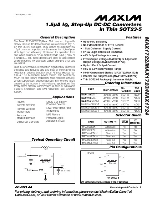
MAX1722
FB 3
4
OUT
THIN SOT23-5
Pin Configurations are continued at end of data sheet.
________________________________________________________________ Maxim Integrated Products
元器件交易网
19-1735; Rev 0; 7/01
1.5µA IQ, Step-Up DC-DC Converters in Thin SOT23-5
General Description
The MAX1722/MAX1723/MAX1724 compact, high-efficiency, step-up DC-DC converters are available in tiny, 5pin thin SOT23 packages. They feature an extremely low 1.5µA quiescent supply current to ensure the highest possible light-load efficiency. Optimized for operation from one to two alkaline or nickel-metal-hydride (NiMH) cells, or a single Li+ cell, these devices are ideal for applications where extremely low quiescent current and ultra-small size are critical. Built-in synchronous rectification significantly improves efficiency and reduces size and cost by eliminating the need for an external Schottky diode. All three devices feature a 0.5Ω N-channel power switch. The MAX1722/ MAX1724 also feature proprietary noise-reduction circuitry, which suppresses electromagnetic interference (EMI) caused by the inductor in many step-up applications. The family offers different combinations of fixed or adjustable outputs, shutdown, and EMI reduction (see Selector Guide). o o o o o o o o o o o
Mill-Max Swage Tooling Kit 使用说明书

SW AGE TOOL USERMANUAL Mill-Max Mfg. Corp. • 190 Pine Hollow Road • Oyster Bay, NY 11771 516-922-6000 • Fax: 516-922-9253 • Introduction:Use this instruction manual with your Mill-Max Swage Tooling Kit to achieve a secure and professional swage. For a complete cross reference list of available punch and anvil kits visit /swagetooling .Alignment:1. Place punch into chuck or ram of press and secure.2. Place anvil into tool holder with desired hole facing up. Do not secure.3. Align punch and anvil by lowering punch, such that the tip is lightly resting inside the anvil, see Figure 1. This will allow the anvil to center itself with the punch. 4. Once the anvil and punch are perfectly aligned and straight, secure anvil.Be sure the anvil does not shift out of alignment when securing. Alignment is critical to a strong and secure swage.Swage Procedure:1. Place pin into anvil with hollow shank of pin facing up. The pin shoulder should be resting on the top surface of anvil and will act as support during the swaging process.2. Place pre-drilled PCB over the hollow shank of the pin.3. Use press to bring the punch down, applying pressure on the hollow shank of the pin, flaring it, and securing it to the PCB.Inspecting the Swage:Shown below are examples of a well-formed and a poorly-formed swage. Pressing with too much force will cause the swaged area to fracture and create an unreliable swage. Conversely, pressing with too little force will not flare the hollow shank enough and the pin will not be secure in the PCB. For additional guidance for inspecting a swage refer to Mil-T-55155.Note: Proper punch and anvil must be used based on part size to achieve secure and professional swage.Figure 1: Tool Alignment Figure 2: Swage Layout Figure 3: Example of a well-formed swage Figure 4: Example of a poorly-formed swage。
MAX2605-MAX2609中文资料
General DescriptionThe MAX2605–MAX2609 evaluation kits (EV kits) simplify evaluation of this family of voltage-controlled oscillators (VCOs). These kits enable testing of the devices’ per-formance and require no additional support circuitry.Both signal outputs use SMA connectors to facilitate connection to RF test equipment.These EV kits are fully assembled and tested. Their oscil-lation frequencies are set to approximately the midrange of the respective VCOs.Featureso Easy Evaluationo Complete, Tunable VCO Test Board with Tank Circuit o Low Phase Noiseo Fully Assembled and TestedEvaluate: MAX2605–MAX2609MAX2605–MAX2609 Evaluation Kits19-1673 Rev 0; 9/00Ordering InformationComponent SuppliersFor free samples and the latest literature, visit or phone 1-800-998-8800.For small orders, phone 1-800-835-8769.MAX2606 Component ListMAX2605 Component ListE v a l u a t e : M A X 2605–M A X 2609MAX2605–MAX2609 Evaluation Kits 2_______________________________________________________________________________________Quick StartThe MAX2605–MAX2609 evaluation kits are fully assembled and factory tested. Follow the instructions in the Connections a nd Setup section for proper device evaluation.Test Equipment Required•Low-noise power supplies (these are recommended for oscillator noise measurement). Noise or ripple will frequency-modulate the oscillator and cause spectral spreading. Batteries can be used in place of power supplies, if necessary.– Use a DC power supply capable of supplying +2.7V to +5.5V. Alternatively, use two or three 1.5V batteries.– Use a DC power supply capable of supplying +0.4V to +2.4V, continuously variable, for TUNE.Alternatively, use two 1.5V batteries with a resistive voltage divider or potentiometer.•An RF spectrum analyzer that covers the operating frequency range of the MAX2605–MAX2609• A 50Ωcoaxial cable with SMA connectors •An ammeter (optional)Connections and Setup1)Connect a DC supply (preset to +3V) to the V CC and GND terminals (through an ammeter, if desired) on the EV kit.2)Turn on the DC supply. If used, the ammeter readingMAX2607 Component ListMAX2608 Component ListEvaluate: MAX2605–MAX2609MAX2605–MAX2609 Evaluation Kits_______________________________________________________________________________________3approximates the typical operating current specified in the MAX2605–MAX2609 data sheet.3)Connect the VCO output (OUT+ or OUT-) to a spec-trum analyzer with a 50Ωcoaxial cable.4)Apply a positive variable DC voltage between 0.4V and 2.4V to TUNE.5)Check the tuning bandwidth on the spectrum analyz-er by varying the tuning voltage (+0.4V to +2.4V).Layout ConsiderationsThe EV kit PC board can serve as a guide for laying out a board using the MAX2605–MAX2609. Generally, the VCC pin on the PC board should have a decoupling capacitor placed close to the IC. This minimizes noisecoupling from the supply. Also, place the VCO as far away as possible from the noisy section of a larger sys-tem, such as a switching regulator or digital circuits.The VCO ’s performance is strongly dependent on the availability of the external tuning inductor. For best per-formance, use high-Q components and choose their val-ues carefully. To minimize the effects of parasitic ele-ments, which degrade circuit performance, place the tuning inductor and C BYP close to the VCO. For higher-frequency versions, include the parasitic PC board inductance and capacitance when calculating the oscillation frequency. In addition, remove the ground plane around and under the tuning inductor to minimize the effect of parasitic capacitance.Noise on TUNE translates into FM noise on the outputs;therefore, keep the trace between TUNE and the control circuitry as short as possible. If necessary, use an RC filter to further suppress noise, as done on the EV kits.E v a l u a t e : M A X 2605–M A X 2609MAX2605–MAX2609 Evaluation Kits 4_______________________________________________________________________________________Figure 2. MAX2608/MAX2609 EV Kits SchematicFigure 1. MAX2605/MAX2606/MAX2607 EV Kits SchematicEvaluate: MAX2605–MAX2609MAX2605–MAX2609 Evaluation Kits_______________________________________________________________________________________5Figure 3. MAX2605/MAX2606/MAX2607 EV Kits ComponentPlacement Guide—Top Silk ScreenFigure 4. MAX2608/MAX2609 EV Kits Component PlacementGuide—Top Silk ScreenFigure 5. MAX2605/MAX2606/MAX2607 EV Kits PC BoardLayout—Component SideFigure 6. MAX2608/MAX2609 EV Kits PC Board Layout—Component SideMa xim ca nnot a ssume responsibility for use of a ny circuitry other tha n circuitry entirely embodied in a Ma xim product. No circuit pa tent licenses a re implied. Maxim reserves the right to change the circuitry and specifications without notice at any time.6_____________________Maxim Integrated Products, 120 San Gabriel Drive, Sunnyvale, CA 94086 408-737-7600©2000 Maxim Integrated ProductsPrinted USAis a registered trademark of Maxim Integrated Products.E v a l u a t e : M A X 2605–M A X 2609MAX2605–MAX2609 Evaluation Kits Figure 7. MAX2605/MAX2606/MAX2607/MAX2608/MAX2609EV Kits PC Board Layout—Ground Plane。
MAX793T中文资料

Voltage Can Exceed VCC o On-Board Gating of Chip-Enable Signals—7ns
Max Propagation Delay
元器件交易网
19-0366; Rev 1; 1/96
MAX793/MAX794/MAX795
3.0V/3.3V Adjustable Microprocessor Supervisory Circuits
_______________General Description
MAX793
WDO
CE IN
MR
WDI
PFO
LOWLINE
ADDRESS DECODER
VCC
VCC A0-A15
I/O NMI
µP
PFI
RESET
BATT OK
GND
RESET
________________________________________________________________ Maxim Integrated Products 1
Output Current VOUT................................................................................200mA All Other Outputs ..............................................................20mA
Pin Configurations appear at end of data sheet.
光宝科技 MaxTester 730C PON metro OTDR 规格手册说明书

S P E C S H E E TN E W O T D R G E N E R A T I O NKEY FEATURESHandy, lightweight, powerful, tablet-inspired design Rugged design built for outside plant7-inch, outdoor-enhanced touchscreen–the biggest in the handheld industry 12-hour battery lifeTamper-proof password protectionDynamic range up to 39 dB for up to 132 km point-to-point (P2P)Short dead zones: event dead zone (EDZ) = 0.5 m;attenuation dead zone (ADZ) = 2.5 m; PON dead zone = 30 m Single port for in-service troubleshooting with in-line 1490/1550 nm PON power meter (optional)iOLM-ready: one-touch multiple acquisitions, with clear go/no-go results presented in a straightforward visual format Supports high port count PON splitters (up to 1x128)Live fiber testing at 1625 nm or 1650 nmAPPLICATIONSFTTx/PON testing through splitters Access network testing (P2P)Metro links testing (P2P)Live fiber troubleshooting Passive optical LAN (POL)MaxTester 730C PON/metro OTDRFully featured, entry-level, dedicated OTDR with tablet-inspired design, suitable for metro and optimized to test through optical splitters, for seamless end-to-end FTTH characterization and troubleshooting.OPTIMIZED FOR FTTx/MDU FIBER DEPLOYMENTS AND TROUBLESHOOTING, SUITABLE FOR METROCOMPLEMENTARY PRODUCTS AND OPTIONSFiber inspection scope FIP-400B (WiFi or USB)Data post-processing software FastReporter 3Soft pulse suppressor bag SPSBTHE HANDHELD OTDR. . . REINVENTED.The MaxTester 700B/C Series is the first tablet-inspired OTDR line that is handy, lightweight and rugged enough for any outside plant environment. With a 7-inch, outdoor-enhanced touchscreen–the most efficient handheld display in the industry–it delivers an unprecedented user experience. Its intuitive Windows-like GUI ensures a fast learning curve. Plus, its new and improved OTDR 2 environment offers icon-based functions, instant boot-up, automatic macrobend finders as well as improved auto and real-time modes.The MaxTester 700B/C Series is a line of genuine high-performance OTDRs from the world’s leading manufacturer. It delivers EXFO’s tried and true OTDR quality and accuracy along with the best optical performance for right-first-time results, every time. The amazing 12-hour battery life will never let a technician down, and the plug-and-play hardware options, like the VFL, power meter and USB tools, make every technician’s job easier.Most importantly, the MaxTester 700B/C Series is finally bringing the intelligent Optical Link Mapper (iOLM), an intelligent OTDR-based application, to the handheld market. This advanced software turns even the most complex trace analysis into a simple, one-touch task.Ultimately, the MaxTester 700B/C Series is small enough to fit in your hand and big enough to fit all your needs!THE ENTRY-LEVEL SOLUTION DESIGNED FOR ALL YOUR TESTING NEEDSThe MaxTester 730C PON/metro OTDR is optimized to test through optical splitters up to 1x128, ensuring complete end-to-end FTTH characterization. The 1625-nm or 1650-nm, out-of-band, live testing port enables the efficient troubleshooting of active networks without affecting the signal of other clients. Plus, the high dynamic range makes it suitable for metro P2P testing. Other models available:•MaxTester 715B short access and FTTx last-mile installation and troubleshooting•MaxTester 720C LAN/WAN access OTDR—optimized for multimode and singlemode access network construction and troubleshooting SECURE YOUR INVESTMENT AGAINST THEFTProtected instruments have no value on the black market making them completely unappealing to thieves.With our security management option, administrators can define and load a tamper-proof security profileon the MaxTester, displaying a property message on the home screen and securing it with a user password(permanent or renewable).LOOKING FOR ICON-BASED MAPPING?Linear view (included on all EXFO OTDRs)Available on our OTDRs since 2006, the linear view simplifies the reading of an OTDR trace by displaying icons in a linear way for each wavelength. This view converts the graph data points obtained from a traditional single pulse trace into reflective, non-reflective or splitter icons. With applied pass/fail thresholds, it becomes easier to pinpoint faults on your link.This improved linear view offers you the flexibility to display both theOTDR graph and its linear view without having to perform a toggleto analyze your fiber link.Although this linear view simplifies OTDR interpretation of a singlepulse-width trace, the user must still set the OTDR parameters.In addition, multiple traces must often be performed in order tofully characterize the fiber links. See the section below to learnabout how the iOLM can perform this automatically and with moreaccurate results.OTDR testing comes withits load of challenges...In response to these challenges, EXFO developed a better way to test fiber optics:application designed to simplify OTDR testing by eliminating the need to configure parameters, and/or analyze and interpret multiple complex OTDR traces. Its advanced algorithms dynamically define the testing parameters, as well as the number of acquisitions that best fit the network under test. By correlating multipulse widths on multiple wavelengths, the iOLM locates and identifiesIn addition to the standard iOLM feature set, you can select added-value features as part of the Order a unit with the iOLM application onlyCOMBORun both iOLM and OTDR applications (Oi code)Add the iOLM software option to your iOLM-ready unit, even while in the fieldGET THE BEST OUT OF YOUR DATA POST-PROCESSING— ONE SOFTWARE DOES IT ALLThis powerful reporting software is the perfect complement to your OTDR, and can be used to create and customize reports to fully address your needs.OPTICAL PLUG-AND-PLAY OPTIONSThe MaxTester features plug-and-play optical options that can be purchased whenever you need them: at the time of your order or later on. In either case, installation is a snap, and can be performed by the user without the need for any software update. Optical power meterEXFO’s high-level power meter (GeX) can measure up to 27 dBm, the highest in the industry. This is essential for hybrid fiber-coaxial (HFC) networks or high-power signals. If used with an auto-lambda/auto-switching compatible light source, the power meter automatically synchronizes on the same wavelength, thus avoiding any risk of mismatched measurement.•Extensive range of connectors•Auto-lambda and auto-switching•Offers measurement storage and reporting•Seven standard calibrated wavelengthsVisual fault locator (VFL)The plug-and-play VFL easily identifies breaks, bends, faulty connectors and splices, in addition to other causes of signal loss. This basic, yet essential troubleshooting tool should be part of every field technician’s toolbox. The VFL visually locates and detects faults over distances of up to 5 km by creating a bright-red glow at the exact location of the fault on singlemode or multimode fibers (available with the optical power meter only).FIBER CONNECTOR INSPECTION AND CERTIFICATION–THE ESSENTIAL FIRST STEP BEFORE ANY OTDR TESTING Taking the time to properly inspect a fiber-optic connector using an EXFO fiber inspection scope can prevent a host of issues from arising further down the line, thus saving you time, money and trouble. Moreover, using a fully automated solution with autofocus capabilities will turn this critical inspection phase into a fast and hassle-free one-step process.Did you know that the connector of your OTDR/iOLM is also critical?The presence of a dirty connector at an OTDR port or launch cable can negatively impact your test results, and even cause permanent damage during mating. Therefore, it is critical to regularly inspect these connectors to ensure that they are free of any contamination. Making inspection the first step of your OTDR best practices willmaximize the performances of your OTDR and your efficiency.PACKAGED FOR EFFICIENCY1Singlemode OTDR port610/100 Mbit/s Ethernet port11 2Singlemode Live OTDR port7Two USB 2.0 ports12 3Stylus8AC adapter13 4Power meter9Home/switch application andscreen capture (hold)5Visual fault locator10Power on/off/stand by123456789101113SOFTWARE UTILITIESSoftware update Ensure that your MaxTester is up-to-date with the latest software.VNC configuration The Virtual Network Computing (VNC) utility allows technicians to easily remote control the unit via a computer or laptop. Microsoft Internet Explorer Access the Web directly from your device interface.Data mover Transfer all your daily test results quickly and easily.Centralized documentation Instant access to user guides and other relevant documents.Wallpapers Enhance your work environment with colorful and scenic backgrounds.PDF Reader View your reports in PDF format.Bluetooth file sharing Share files between your MaxTester and any Bluetooth-enabled device.WiFi connection WiFi FIP inspection scope interface. Upload test results and browse the Internet.Inspection scope USB or WiFi scope to inspect and analyze connectors.FTP server Exchange files over WiFi to an FTP application on a smartphone for easier file sharing from the field.Security management Tamper-proof security profile with user password (permanent or renewable) and custom property message.SPECIFICATIONS a。
- 1、下载文档前请自行甄别文档内容的完整性,平台不提供额外的编辑、内容补充、找答案等附加服务。
- 2、"仅部分预览"的文档,不可在线预览部分如存在完整性等问题,可反馈申请退款(可完整预览的文档不适用该条件!)。
- 3、如文档侵犯您的权益,请联系客服反馈,我们会尽快为您处理(人工客服工作时间:9:00-18:30)。
General DescriptionThe MAX6305–MAX6313 CMOS microprocessor (µP)supervisory circuits are designed to monitor more than one power supply. Ideal for monitoring both 5V and 3.3V in personal computer systems, these devices assert a system reset if any of the monitored supplies falls outside the programmed threshold. Low supply current (15µA) and a small package suit them for portable applications. The MAX6305–MAX6313 are specifically designed to ignore fast transients on any monitored supply.These devices are available in a SOT23-5 package,have factory-programmed reset thresholds from 2.5V to 5.0V (in 100mV increments), and feature four power-on reset timeout periods. Ten standard versions are avail-able. Contact the factory for availability of non standard versions.ApplicationsPortable Computers Computers ControllersIntelligent InstrumentsPortable/Battery-Powered Equipment Multivoltage Systems: 3V/5V, 5V/12V, 5V/24V Embedded Control SystemsFeatureso Small 5-Pin SOT23 Packageo Precision Factory-Set V CC Reset Thresholds;Available in 0.1V Increments from 2.5V to 5V o Immune to Short V CC Transientso Guaranteed RESET Valid to V CC = 1V o Guaranteed Over Temperature o 8µA Supply Currento Factory-Set Reset Timeout Delay from 1ms (min) to 1120ms (min)o No External Components o Manual Reset Inputo Under/Overvoltage Supply MonitoringMAX6305–MAX63135-Pin, Multiple-Input,Programmable Reset ICs________________________________________________________________Maxim Integrated Products119-1145; Rev 5; 4/08†The MAX6306/MAX6307/MAX6309/MAX6310/MAX6312/MAX6313 are available with factory-set V CC reset thresholds from 2.5V to 5V, in 0.1V increments. Insert the desired nominal reset threshold (from Table 1) into the blanks following the letters UK.All parts also offer factory-programmed reset timeout periods.Insert the number corresponding to the desired nominal timeout period index following the “D” in the part number (D1 = 1ms min,D2 = 20ms min, D3 = 140ms min, and D4 = 1120ms min). There are 10 standard versions with a required order increment of 2,500pieces. Sample stock is generally held on the standard versions only (see Standard Versions table). Required order increment is 10,000 pieces for non-standard versions. Contact factory for availability of non-standard versions. All devices available in tape-and-reel only.Devices are available in both leaded and lead-free packaging.Specify lead-free by replacing “-T” with “+T” when ordering.Pin Configurations and Typical Operating Circuit appear atend of data sheet.Ordering Information continued at end of data sheet.Standard Versions Table appears at end of data sheet._______________________________________________________________Selector TableFor pricing, delivery, and ordering information, please contact Maxim Direct at 1-888-629-4642,or visit Maxim’s website at .M A X 6305–M A X 63135-Pin, Multiple-Input, Programmable Reset ICsABSOLUTE MAXIMUM RATINGSELECTRICAL CHARACTERISTICSV CC = +2.5V to +5.5V for the MAX6305/MAX6308/MAX6311, V CC = (V TH + 2.5%) to +5.5V for the MAX6306/MAX6307/MAX6309/Stresses beyond those listed under “Absolute Maximum Ratings” may cause permanent damage to the device. These are stress ratings only, and functional operation of the device at these or any other conditions beyond those indicated in the operational sections of the specifications is not implied. Exposure to absolute maximum rating conditions for extended periods may affect device reliability.V CC ...........................................................................-0.3V to +6V All Other Pins..............................................-0.3V to (V CC + 0.3V)Input/Output Current, All Pins.............................................20mA Rate of Rise, V CC ............................................................100V/µs Continuous Power Dissipation (T A = +70°C)SOT23-5 (derate 7.1mW/°C above +70°C).................571mWOperating Temperature RangeMAX63_ _UK _ _D_-T.........................................0°C to +70°C MAX63_ _EUK _ _D_-T...................................-40°C to +85°C Storage Temperature Range.............................-65°C to +160°C Lead Temperature (soldering, 10sec).............................+300°CMAX6305–MAX63135-Pin, Multiple-Input, Programmable Reset ICs_______________________________________________________________________________________3ELECTRICAL CHARACTERISTICS (continued)V CC = +2.5V to +5.5V for the MAX6305/MAX6308/MAX6311, V CC = (V TH + 2.5%) to +5.5V for the MAX6306/MAX6307/MAX6309/Note 2: The MAX6305/MAX6308/MAX6311 switch from undervoltage reset to normal operation between 1.5V < V CC < 2.5V.Note 3: The MAX6306/MAX6307/MAX6309/MAX6310/MAX6312/MAX6313 monitor V CC through an internal factory-trimmed voltagedivider, which programs the nominal reset threshold. Factory-trimmed reset thresholds are available in approximately 100mV increments from 2.5V to 5V (Table 1).Note 4:Guaranteed by design.M A X 6305–M A X 63135-Pin, Multiple-Input, Programmable Reset ICs 4_________________________________________________________________________________________________________________________________Typical Operating Characteristics(V CC = +5V, T A = +25°C, unless otherwise noted.)5.05.56.06.57.07.58.08.59.09.5-60-40-2020406080100SUPPLY CURRENT vs. TEMPERATURETEMPERATURE (°C)S U P P L Y C U R R E N T (μA )01020304050607080-60-40-2020406080100V CC FALLING PROPAGATION DELAYvs. TEMPERATURETEMPERATURE (°C)P R O P A G A T I O N D E L A Y (n s )010203040506070-60-40-20020406080100OVRST IN RISING PROPAGATION DELAY vs. TEMPERATURE (OVERVOLTAGE RESET INPUT)TEMPERATURE (°C)P R O P A G A T I O N D E L A Y (n s )020406080100120-60-40-2020406080100RST IN_ FALLING PROPAGATION DELAY vs. TEMPERATURETEMPERATURE (°C)R S T I N _ P R O P A G A T I O N D E L A Y (n s )104001200800MAXIMUM TRANSIENT DURATION vs.VCC RESET THRESHOLD OVERDRIVE10OVERDRIVE, V TH - V CC (mV)T R A N S I E N T D U R A T I O N (μs )100100010,0000.900.920.940.960.981.001.021.041.061.081.10-60-40-20020406080100RESET TIMEOUT vs. TEMPERATURE6305 T O C 05TEMPERATURE (°C)N O R M A L I Z E D R E S E T T I M E O U T0.9900.9920.9940.9960.9981.0001.0021.0041.0061.0081.010-60-40-2020406080100RESET THRESHOLD vs. TEMPERATURE6305 T O C 06TEMPERATURE (°C)N O R M A L I Z E D R E S E T T H R E S H O L D (V /V )104001200800MAXIMUM TRANSIENT DURATION vs.OVRST IN THRESHOLD OVERDRIVE10OVERDRIVE, V OVRST IN - V REF (mV)T R A N S I E N T D U R A T I O N (μs )100100010,000104001200800MAXIMUM TRANSIENT DURATION vs.RST IN_ THRESHOLD OVERDRIVE10OVERDRIVE, V REF - V RST IN (mV)T R A N S I E N T D U R A T I O N (μs )100100010,000_______________Detailed DescriptionThe MAX6305–MAX6313 CMOS microprocessor (µP)supervisory circuits are designed to monitor more than one power supply and issue a system reset when any monitored supply falls out of regulation. The MAX6305/MAX6308/MAX6311 have two adjustable undervoltage reset inputs (RST IN1 and RST IN2). The MAX6306/MAX6307/MAX6309/MAX6310/MAX6312/MAX6313 mon-itor V CC through an internal, factory-trimmed voltage divider. The MAX6306/MAX6309/MAX6312 have, in addition, an adjustable undervoltage reset input and a manual-reset input. The internal voltage divider sets the reset threshold as specified in the device part number (Table 1). The MAX6307/MAX6310/ MAX6313 feature an adjustable undervoltage reset input (RST IN) and an adjustable overvoltage reset input (OVRST IN) in addition to the factory-trimmed reset threshold on the V CC moni-tor. Program the adjustable reset inputs with an external resistor divider (see Adjustable Reset Inputs section).Reset OutputsA µP’s reset input starts the µP in a known state. These µP supervisory circuits assert reset to prevent code-execution errors during power-up, power-down, or brownout conditions.RESET (MAX6305–MAX6310) and RESET (MAX6311/MAX6312/MAX6313) are guaranteed to be asserted at a valid logic level for V CC > 1V (see Electrical Characteristics ). Once all monitored voltages exceed their programmed reset thresholds, an internal timer keeps reset asserted for the reset timeout period (t RP );after this interval, reset deasserts.If a brownout condition occurs (any or all monitored volt-ages dip outside their programmed reset threshold),reset asserts (RESET goes high; RESET goes low). Any time any of the monitored voltages dip below their reset threshold, the internal timer resets to zero and reset asserts. The internal timer starts when all of the moni-tored voltages return above their reset thresholds, and reset remains asserted for a reset timeout period. The MAX6305/MAX6306/MAX6307 feature an active-low,MAX6305–MAX63135-Pin, Multiple-Input, Programmable Reset ICs_______________________________________________________________________________________5______________________________________________________________Pin DescriptionM A X 6305–M A X 6313open-drain, N-channel output. The MAX6308/MAX6309/MAX6310 feature an active-low, complementary output structure that both sinks and sources current, and the MAX6311/MAX6312/MAX6313 have an active-high com-plementary reset output.The MAX6305/MAX6308/MAX6311 switch from under-voltage lockout operation to normal operation between 1.5V < V CC < 2.5V. Below 1.5V, V CC undervoltage-lockout mode asserts RESET . Above 2.5V, V CC normal-operation mode asserts reset if RST IN_ falls below the RST IN_ threshold.Manual-Reset Input(MAX6306/MAX6309/MAX6312)Many µP-based products require manual-reset capability,allowing an operator or external logic circuitry to initiate a reset. A logic low on MR asserts reset. Reset remains asserted while MR is low, and for a reset active timeout period (t RP ) after MR returns high. This input has an inter-nal 63.5k Ωpull-up resistor, so it can be left open if it is not used. MR can be driven with TTL-logic levels in 5V sys-tems, with CMOS-logic levels in 3V systems, or with open-drain/collector output devices. Connect a normally open momentary switch from MR to GND to create a manual-reset function; external debounce circuitry is not required.If MR is driven from long cables or if the device is used in a noisy environment, connecting a 0.1µF capacitor from MR to ground provides additional noise immunity.The MR pin has internal ESD-protection circuitry that may be forward biased under certain conditions, drawing excessive current. For example, assume the circuitry driv-ing MR uses a +5V supply other than V CC . If V CC drops or browns out lower than +4.7V, MR ’s absolute maximum rat-ing is violated (-0.3V to (V CC + 0.3V)), and undesirable current flows through the ESD structure from MR to V CC .To avoid this, it is recommended that the supply for the MR pin be the same as the supply monitored by V CC . In this way, the voltage at MR will not exceed V CC .Adjustable Reset InputsThe MAX6305–MAX6313 each have one or more reset inputs (RST IN_ /OVRST IN). These inputs are com-pared to the internal reference voltage (F igure 1).Connect a resistor voltage divider to RST IN_ such that V RST IN_falls below V RSTH (1.23V) when the monitored voltage (V IN ) falls below the desired reset threshold (V TH ) (F igure 2). Calculate the desired reset voltage with the following formula:R1 + R2V TH = ________x VRSTHR25-Pin, Multiple-Input, Programmable Reset ICs 6_______________________________________________________________________________________Figure 1. Functional DiagramMAX6305–MAX63135-Pin, Multiple-Input, Programmable Reset ICs_______________________________________________________________________________________7The ±25nA max input leakage current allows resistors on the order of megohms. Choose the pull-up resistor in the divider to minimize the error due to the input leakage cur-rent. The error term in the calculated threshold is simply:±25nA x R1If you choose R1 to be 1M Ω, the resulting error is ±25 x 10-9x 1 x 106= ±25mV.Like the V CC voltage monitors on the MAX6306/MAX6307/MAX6309/MAX6310/MAX6312/MAX6313, the RST IN_inputs (when used with a voltage divider) are designed to ignore fast voltage transients. Increase the noise immunity by connecting a capacitor on the order of 0.1µF between RST IN and GND (Figure 2). This creates a single-pole lowpass filter with a corner frequency given by:f = (1/2π) / (R1 + R2)(R1 x R2 x C)For example, if R1 = 1M Ωand R2 = 1.6M Ω, adding a 0.1µF capacitor from RST IN_ to ground results in a lowpass corner frequency of f = 2.59Hz. Note that adding capacitance to RST IN slows the circuit’s overall response time.__________Applications InformationInterfacing to µPs with Bidirectional Reset PinsSince the RESET output on the MAX6305/MAX6306/MAX6307 is open drain, these devices interface easily with µPs that have bidirectional reset pins, such as the Motorola 68HC11. Connecting the µP supervisor’s RESET output directly to the microcontroller’s RESET pin with a single pull-up resistor allows either device to assert reset (Figure 3).Negative-Going V CC TransientsIn addition to issuing a reset to the µP during power-up,power-down, and brownout conditions, these devices are relatively immune to short-duration, negative-going V CC transients (glitches).The Typical Operating Characteristics show the Maximum Transient Duration vs. V CC Reset Threshold Overdrive, for which reset pulses are not generated.The graph was produced using negative-going pulses,starting at V TH max, and ending below the pro-grammed reset threshold by the magnitude indicated (reset threshold overdrive). The graph shows the maxi-mum pulse width that a negative-going V CC transient may typically have without causing a reset pulse to be issued. As the amplitude of the transient increases (i.e.,goes farther below the reset threshold), the maximum allowable pulse width decreases.RST IN_/OVRST IN are also immune to negative/positive-going transients (see Typical Operating Characteristics ).A 0.1µF bypass capacitor mounted close to the RST IN_,OVRST IN, and/or the V CC pin provides additional tran-sient immunity.Ensuring a Valid RESET /RESETOutput Down to V CC = 0VWhen V CC falls below 1V, push/pull structured RESET /RESET current sinking (or sourcing) capabilities decrease drastically. High-impedance CMOS-logic inputs connected to RESET can drift to undetermined voltages. This presents no problem in most applica-tions, since most µPs and other circuitry do not operate with V CC below 1V. In those applications where RESET must be valid down to 0V, adding a pull-down resistor between RESET and ground sinks any stray leakageFigure 2. Increasing Noise ImmunityFigure 3. Interfacing to µPs with Bidirectional Reset I/Ocurrents, holding RESET low (Figure 4). The pull-down resistor’s value is not critical; 100k Ωis large enough not to load RESET and small enough to pull RESET to ground. For applications where RESET must be valid to V CC , a 100k Ωpull-up resistor between RESET and V CC will hold RESET high when V CC falls below 1V (Figure 5).Since the MAX6305/MAX6306/MAX6307 have open-drain, active-low outputs, they typically use a pull-up resistor. With these devices and under these conditions (V CC < 1V), RESET will most likely not maintain an active condition, but will drift toward a nonactive level due to the pull-up resistor and the RESET output’s reduction in sinking capability. These devices are not recommended for applications that require a valid RESET output below 1V.* Factory-trimmed reset thresholds are available in approximately 100mV increments with a ±1.5% room-temperature variance.M A X 6305–M A X 63135-Pin, Multiple-Input, Programmable Reset ICs 8_______________________________________________________________________________________Figure 4. Ensuring RESET Valid to V CC = 0VFigure 5. Ensuring RESET Valid to V CC = 0VTable 1. Factory-Trimmed Reset Thresholds*MAX6305–MAX63135-Pin, Multiple-Input, Programmable Reset ICs_______________________________________________________________________________________9Chip InformationTRANSISTOR COUNT: 800Typical Operating Circuit†The MAX6306/MAX6307/MAX6309/MAX6310/MAX6312/MAX6313 are available with factory-set V CC reset thresholds from 2.5V to 5V, in 0.1V increments. Insert the desired nominal reset threshold (from Table 1) into the blanks following the letters UK.All parts also offer factory-programmed reset timeout periods.Insert the number corresponding to the desired nominal timeout period index following the “D” in the part number (D1 = 1ms min,D2 = 20ms min, D3 = 140ms min, and D4 = 1120ms min). There are 10 standard versions with a required order increment of 2,500pieces. Sample stock is generally held on the standard versions only (see Standard Versions table). Required order increment is 10,000 pieces for non-standard versions. Contact factory for avail-ability of non-standard versions. All devices available in tape-and-reel only.Devices are available in both leaded and lead-free packaging.Specify lead-free by replacing “-T” with “+T” when ordering.M A X 6305–M A X 63135-Pin, Multiple-Input, Programmable Reset ICs 10______________________________________________________________________________________Pin ConfigurationsPackage InformationFor the latest package outline information, go to /packages .Maxim cannot assume responsibility for use of any circuitry other than circuitry entirely embodied in a Maxim product. No circuit patent licenses are implied. Maxim reserves the right to change the circuitry and specifications without notice at any time.Maxim Integrated Products, 120 San Gabriel Drive, Sunnyvale, CA 94086 408-737-7600 ____________________11©2008 Maxim Integrated Productsis a registered trademark of Maxim Integrated Products, Inc.MAX6305–MAX6313 5-Pin, Multiple-Input, Programmable Reset ICs元器件交易网。