InFocus_Mondopad_Datasheet_CN20111021
微Focus VisiBroker 8.5 SP4 Dual IPv4 IPv6 OSAgent更新

Micro FocusThe Lawn22-30 Old Bath RoadNewbury, Berkshire RG14 1QNUKCopyright © Micro Focus 2009-2017. All rights reserved.MICRO FOCUS, the Micro Focus logo, and Micro Focus product names are trademarks or registered trademarks of Micro Focus Development Limited or its subsidiaries or affiliated companies in the United States, United Kingdom, and other countries. All other marks are the property of their respective owners.Revised 2017-06-02ContentsMicro Focus VisiBroker 8.5.4 Dual IPv4/IPv6 OSAgent Update Release Notes . 2 Installing this Update (2)Before Installing the IPv4/IPv6 OSAgent Update (2)Operating Systems Supported (2)Installing the IPv4/IPv6 OSAgent Update (2)Patching the vbj.config file (3)Introduction (3)Default Behavior (3)Compatibility (3)New Configuration Variables (4)Enabling IPv6 (4)Locating Smart Agents (5)Configuring Smart Agent Locations (5)Smart Agent Discovery (5)Controlling Local Addresses in Use (6)Updates and SupportLine (7)Further Information and Product Support (7)Disclaimer (7)Micro Focus VisiBroker 8.5.4 Dual IPv4/IPv6 OSAgent Update Release Notes | 1Micro Focus VisiBroker 8.5.4Dual IPv4/IPv6 OSAgent Update Release NotesInstalling this UpdateBefore Installing the IPv4/IPv6 OSAgent UpdateThis release updates VisiBroker 8.5 SP4. Before installing this release, you must have VisiBroker 8.5 SP4 installed.Operating Systems SupportedAt this release, the following platforms are supported:∙Microsoft Windows 7 with Visual Studio 2008∙Microsoft Windows Server 2008 with Visual Studio 2008∙Solaris 10.x (SPARC)∙Solaris 10.x (x86 and x64)∙Solaris 11.x (SPARC)∙Solaris 11.x (x86 and x64)∙Red Hat Enterprise Linux 5.x (x86 and x64)∙Red Hat Enterprise Linux 6.x (x86 and x64)∙Red Hat Enterprise Linux 7.x (x86 and x64)∙SUSE Linux Enterprise Server 10.x (x86 and x64)∙SUSE Linux Enterprise Server 11.x (x86 and x64)∙SUSE Linux Enterprise Server 12.x (x86 and x64)∙HP UX 11i v3/11.31 on Itanium∙AIX 6.x (32 or 64 bit)∙AIX 7.1 (32 or 64 bit)∙Montavista Linux CGE V4 (x64)For a full list of platforms supported by VisiBroker 8.5 SP4, see/prodavail.aspxInstalling the IPv4/IPv6 OSAgent UpdateTo install this release:1.Download the release archive to your VBROKERDIR folder.2.Unpack the archive in the same folder.3.Patch the vbj.config file (or files) as described in Patching the vbj.config file.4.Restart the application.2 | Micro Focus VisiBroker 8.5.4 Dual IPv4/IPv6 OSAgent Update Release NotesPatching the vbj.config fileThis release introduces two new configuration environment variables: see New Configuration Variables for details.For these variables to be effective for Java applications, or for VisiBroker services written in Java, a change must be made to any vbj.config files in use in your deployment. For more information regarding the default location of this file, and how alternate or additional files might have been configured in your application’s environment, s ee the documentation for the argument –VBJConfig. This argument is listed under “General options”, in the chapter Programmer tools for Java of the VisiBroker for Java Developer’s Guide(https:///Documentation/books/VisiBroker/854/vb_javadg_854.pdf)You can patch the requisite change into the default Java configuration file ($VBROKERDIR/bin/vbj.config). From a command shell configured with your application’s normal VisiBroker environment values set, run:vbj PatchVBJConfigIf you have a non-default configuration file, you must patch it by passing the location of the file to PatchVBJConfig as the value of the option -VBJConfig:vbj -VBJConfig /opt/foo/bar.config PatchVBJConfigIntroductionVisiBroker 8.5 SP4 supports ORB communications over IPv6. This means that, if so configured, object implementation methods can be invoked by client programs overIPv6. However, the Smart Agent (osagent) included with SP4 supports only IPv4, making it impossible to migrate VisiBroker applications that depend upon the Smart Agent to a pure IPv6 environment.This VisiBroker 8.5 SP4 update enables Smart Agent communications over IPv6, in addition to IPv4.See the C++ or Java editions of the VisiBroker Developer’s Guide for more information about how to deploy the Smart Agent. This Release Note complements the information in the Developer’s Guide and provides the additional information required to enable IPv6 Smart Agent communications.Default BehaviorOnce this update has been installed, the default behavior will still be for all Smart Agent communication to use IPv4 only. This means that the new Smart Agent behaves in the same way as the standard Smart Agent when deployed with the same configuration.To use IPv6, you must enable it as described in Enabling IPv6.CompatibilityThe Smart Agent included with this patch is not interoperable with the standard VisiBroker 8.5 SP4 Smart Agent, nor with its associated ORB libraries or .jar files. Because of this incompatibility, you must install and set up the new Smart Agent update Micro Focus VisiBroker 8.5.4 Dual IPv4/IPv6 OSAgent Update Release Notes | 3to all VisiBroker installations in the same Smart Agent ‘domain’ (that is, to all those installations using the same OSAGENT_PORT number).New Configuration VariablesThis release introduces two new configuration environment variables: ∙OSAGENT_IP_MODE. This specifies whether the new Smart Agent should operate in IPv4, IPv6, or dual mode. See Enabling IPv6 for details.∙OSAGENT_MULTICAST_ADDR. If used, this specifies an IPv6 multicast address to override the default address. See Smart Agent Discovery for details. Enabling IPv6Once you have installed this update, you can enable IPv6, either exclusively or in dual mode.To control the IP version in use, you can configure the Smart Agent to operate in one of the following three modes by setting the new OSAGENT_IP_MODE environment variable to the appropriate value:OSAGENT_IP_MODE Descriptionipv4only Smart Agent initializes itself to listenonly on local IPv4 addresses.This is the default behavior.ipv6only Smart Agent initializes itself to listenonly on local IPv6 addresses.Dual Smart Agent initializes itself to listenon both local IPv4 and IPv6addresses. This allows it to becommunicated with by VisiBrokerORBs that are themselvesconfigured to operate in any of thethree IP modes.The VisiBroker ORB may be configured to operate using the same IP modes, either by setting the OSAGENT_IP_MODE environment variable or by setting thevbroker.agent.ipMode property:OSAGENT_IP_MODE/vbroker.agent.ipMode Descriptionipv4only VisiBroker ORB will attempt to findand connect to Smart Agents usingIPv4 only.This is the default behavior.ipv6only VisiBroker ORB will attempt to findand connect to Smart Agents usingIPv6 only.Dual VisiBroker ORB will use both IPv4and IPv6 when attempting to findand connect to Smart Agents.4 | Micro Focus VisiBroker 8.5.4 Dual IPv4/IPv6 OSAgent Update Release NotesLocating Smart AgentsConfiguring Smart Agent LocationsThe VisiBroker ORB can find Smart Agents automatically (see Smart Agent Discovery). However, if the addresses of one or more Smart Agents are already known, the clients and servers can be configured to try to connect to those addresses first.To instruct VisiBroker ORB to try to connect to a Smart Agent at a single address, set either the OSAGENT_ADDR environment variable or the vbroker.agent.addr property: OSAGENT_ADDR=<IP address>vbroker.agent.addr=<IP address>where <IP address> may be IPv4 or IPv6 and must be appropriate to the configured IP mode.Alternatively if multiple Smart Agent addresses are known, you can specify these using an agentaddr file by setting the OSAGENT_ADDR_FILE environment variable or the vbroker.agent.addrFile property:OSAGENT_ADDR_FILE=<path to agentaddr file>vbroker.agent.addrFile=<path to agentaddr file>The agentaddr file should contain a simple list of IP addresses (appropriate to the IP mode), with each address on a new line. The following example shows what the agentaddr file might look like if this Smart Agent was to run in IP mode ‘dual’. There is one Smart Agent listening on an IPv4 address and another on an IPv6 address: # Note comment lines may be included, using ‘#’ as first character10.120.2.6fdb0:4000:f330:2:250:56ff:feb5:539aVisiBroker will try each address in turn until a Smart Agent responds, at which point it will log into and use that Smart Agent from that point on for as long as it remains available.Smart Agent DiscoveryIf the VisiBroker ORB is not able to connect to a Smart Agent using an address provided by either of the OSAGENT_ADDR or OSAGENT_ADDR_FILE methods, it will attempt to find a Smart Agent using IPv4 UDP broadcast and/or IPv6 UDP multicast (dependent on how the IP mode is set) using the port configured as OSAGENT_PORT. The first Smart Agent to respond is used. Similarly individual Smart Agents will use the same mechanisms, subject to the same configuration values, to discover other Smart Agents in the same OSAGENT_PORT domain which they will then communicate with to provide Smart Agent functionality.The default IPv6 multicast address used is ff05::1400. This can be overridden by setting the new desired multicast address using either the OSAGENT_MULTICAST_ADDR environment variable (for both Smart Agent and ORB) or thevbroker.agent.multicastAddress property (ORB only). In order for a Smart Agent to be discovered using IPv6 multicast, both endpoints need to be using the same IPv6 multicast address. IPv4 multicast is not supported.Micro Focus VisiBroker 8.5.4 Dual IPv4/IPv6 OSAgent Update Release Notes | 5Controlling Local Addresses in UseBy default, the Smart Agent will listen on all available network interfaces (as appropriate to the IP mode). Alternatively, you can specify the network interfaces used. This is achieved through configuration of a localaddr file, which is specified via the OSAGENT_LOCAL_FILE environment variable.The section “Specifying interface usage for Smart Agents” in both the VisiBroker forC++ Developer’s Guide and the VisiBroker for Java Developer’s Guide describes the format for the localaddr file that applied to versions of the Smart Agent prior to this update. However, the file format has been simplified for this new Smart Agent; there is no longer any requirement to specify subnet mask or broadcast address for each required interface. The new Smart Agent derives this additional information from the system. All that is required is a list of one or more local IP addresses that you wish the Smart Agent to listen on.The following examples illustrate possible configurations for a host with multiple network interfaces:# localaddr file appropriate for ‘ipv4only’ mode10.120.2.5510.120.3.101# localaddr file appropriate for ‘ipv6only’ modefdb0:4000:f330:2:250:56ff:feb5:300fdb0:4000:f330:3:250:56ff:feb5:1111# localaddr file appropriate for ‘dual’ mode10.120.2.5510.120.3.101fdb0:4000:f330:2:250:56ff:feb5:300Note that localaddr files as configured for the previous versions of the Smart Agent (see “Specifying interface usage for Smart Agents” in the Developer’s Guide s) will continue to be supported by this (and future) versions of the Smart Agent. Values for broadcast address and network mask will continue to be interpreted and used if present in the file.6 | Micro Focus VisiBroker 8.5.4 Dual IPv4/IPv6 OSAgent Update Release NotesUpdates and SupportLineOur Web site gives up-to-date details of contact numbers and addresses.Further Information and Product SupportAdditional technical information or advice is available from several sources.The product support pages contain a considerable amount of additional information, such as:• The WebSync service, where you can download fixes and docum entation updates.• The Knowledge Base, a large collection of product tips and workarounds.• Examples and Utilities, including demos and additional product documentation.To connect, enter https:// in your browser to go to the Micro Focus home page.Note: Some information may be available only to customers who have maintenance agreements.If you obtained this product directly from Micro Focus, contact us as described on the Micro Focus Web site, https://. If you obtained the product from another source, such as an authorized distributor, contact them for help first. If they are unable to help, contact us.DisclaimerThis software is provided "as is" without warranty of any kind. Micro Focus disclaims all warranties, either express or implied, including the warranties of merchantability and fitness for a particular purpose. In no event shall Micro Focus or its suppliers be liable for any damages whatsoever including direct, indirect, incidental, consequential, loss of business profits or special damages, even if Micro Focus or its suppliers have been advised of the possibility of such damages. Some states do not allow the exclusion or limitation of liability for consequential or incidental damages so the foregoing limitation may not apply.Micro Focus is a registered trademark.Copyright © Micro Focus 2017. All rights reserved.Micro Focus VisiBroker 8.5.4 Dual IPv4/IPv6 OSAgent Update Release Notes | 7。
OSRAM DRAGONpuck DP3 Data Sheet
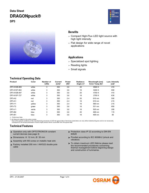
DP3DRAGONpuck®Data SheetPicture for Datasheet is missingBenefitsCompact High-Flux LED light source with high light intensity¾Flat design for wide range of novel applications¾ApplicationsSpecialized spot lighting¾Reading lights ¾Small signals¾Technical FeaturesOperation only with OPTOTRONIC® constantcurrent devices (see page 3)¾Dimensions: H: 12 mm, Ø: 35 mm¾Assembly with M3 screw on metallic heat sink ¾Factory installed 200 mm / AWG22 double polecable¾Protection class IP 22 according to DIN EN60529¾Proofed according to IEC 60068-2 (shock andvibration)¾To obtain maximum LED lifetime please readthe recommended procedures concerning thermal management before beginning design and construction of luminaires.¾Color Power [W]*Radiance Angle [°]*Wavelength [nm] Color Temp [K]*Lum. Intensity[cd]*Current [mA]*Product Number of LEDsTechnical Operating Datawhite 3,6206500 K 410350DP3-W2B-8653white 3,6165400 K 900350DP3-W3F-8543white 3,6204700 K 410350DP3-W2B-8473white 3,6162700 K 630350DP3-W3F-7273red 2,420616 nm 500350DP3-A23red 2,416616 nm 215350DP3-A13yellow 2,416589 nm 215350DP3-Y13green 3,616531 nm 850350DP3-T23verde 3,616505 nm 295350DP3-V13blue 3,620468 nm 115350DP3-B23blue3,616468 nm95350DP3-B13All Data are related to the entire moduleDue to the special conditions of the manufacturing processes of LED the typical data of technical parameters can only reflect statistical figures and do not necessarily correspond to the actual parameters of each single product which could differ from the typical data.*)+)Preliminary DataDrawingDrawing is missingOperating Temperature at Tc-Point [ °C ] *Storage Temperature[ °C ] *Product Reverse Voltage[ V dc ] *Minimum and Maximum RatingsMax. Current [ A dc ] *DP3-W2B-86524-3085-3085......0,5DP3-W3F-85424-3085-3085......0,5DP3-W2B-84724-3085-3085......0,5DP3-W3F-72724-3085-3085......0,5DP3-A224-3085-3085......0,5DP3-A124-3085-3085......0,5DP3-Y124-3085-3085......0,5DP3-T224-3085-3085......0,5DP3-V124-3085-3085......0,5DP3-B224-3085-3085......0,5DP3-B124-3085-3085......0,5Exceeding maximum ratings for operating and storage temperature will reduce expected life time or destroy the LED Module.Exceeding maximum ratings for operating current will cause hazardous overload and will likely destroy the LED Module. Several modules may be connected in series up to the maximum voltage of 100 V DC (outside SELV limits).The temperature of the LED module must be measured at the Tc-point according to EN60598-1 in a thermally constant status with a temperature sensor or a temperature sensitive label. For exact location of the Tc-point see drawing below.*)The module is designed to work with current sources. The maximum output voltage may not exceed 100 V DC. Reverse operation is not allowed and may destroy the module.Safety InformationThe LED module itself and all its components must not be mechanically stressed.¾Assembly must not damage or destroy conducting paths on the circuit board.¾Serial connection is highly recommended as safe electrical operation mode.Parallel connection is not recommended. Unbalanced voltage drop can cause hazardous overload and damage the LED module.Correct electrical polarity needs to be observed. Wrong polarity may destroy the module.¾¾¾Recommended power supply:¾OT 9/200-240/350 or OT 9/100-120/350(E): 350 mA constant current operation¾OT 9/10-24/350 DIM, OT 9/10-24/350 DIM(E): 350 mA constant current PWM dimming, 1..10V interface ¾OT 9/200-240/350 DIM: 0-350 mA constant current operation, 1..10 V interface (dimming), strain relief ¾Maximum number of DP3 for OT9: White/Blue/Green: 2; Red/Yellow: 3¾OT 18/200-240/700 DIM: 0-500 mA constant current operation, 1..10 V interface (dimming), strain relief. The OT18 comes with preset limitation to 500mA, thus giving 12W due to SELV (<=25V)¾Maximum number of LEDs for OT18: White/Blue/Green: 2; Red/Yellow: 3¾Pay attention to standard ESD precautions when installing the module.¾The module, as manufactured, has no conformal coating and therefore offers no inherent protection against corrosion.¾Damage by corrosion will not be honored as a materials defect claim. It is the user's responsibility to provide suitable protection against corrosive agents such as moisture and condensation and other harmful elements.Installation of LED modules (with power supplies) needs to be made with regard to all applicable electrical and safety standards. Only qualified personnel should be allowed to perform installations.¾The LED Module incorporates no protection against short circuits, overload or overheating. Therefore it is absolutely necessary to operate the modules with a electronically stabilised power supply offering protection against the above mentioned safety risks.For dimming applications attention should be paid to specific references in "OPTOTRONIC ® Technical Guide".OSRAM OPTOTRONIC ® power supplies are specifically designed with protection features for safe operation.When using power supplies other than OPTOTRONIC ® the following basic safety features are required, in addition to any other application specific concerns and local safety codes:Short circuit protection ¾Overload protection Overheat protection¾¾Assembly Information¾The mounting of the module is facilitated by means of a M3 screw which fits to a threaded hole in the rear of the DRAGONpuck® housing. Do not exceed a torque of 40 Ncm.¾The module should be in good thermal contact with the designed metallic mounting surface. Use of an appropriate heat sink compound is recommended to eliminate air gaps.¾To obtain maximum LED-lifetime please read carefully the recommended procedures concerning thermal management in ourapplication note "Lifetime of LED-modules" before beginning construction of luminaires. This application note is available from your OSRAM representative.Productgroup Productname EAN *S-Unit *Ordering GuideDRAGONpuck®DP3-W2B-865400832103340616DRAGONpuck®DP3-W3F-8544008321214508DRAGONpuck®DP3-W2B-847400832103336916DRAGONpuck®DP3-W3F-7274008321214447DRAGONpuck®DP3-A2400832114953416DRAGONpuck®DP3-A1400832103318516DRAGONpuck®DP3-Y1400832103342016DRAGONpuck®DP3-T2400832114951016DRAGONpuck®DP3-V1400832103334516DRAGONpuck®DP3-B2400832114947316DRAGONpuck®DP3-B1400832103320816EAN: Ordering number per single module S-Unit: Modules per shipping unit*) Note: Typical performance data are subject to change without any further notice, particularly as LED technology evolves.Related and Further InformationThe new dimension of light ¾153 S006 GBOPTOTRONIC® Data Sheets ¾ OPTOTRONIC® Technical Guide ¾130 T008 GBOSRAM LED systems¾/led-systemsApplication Note: Life Expectancy¾/led-systems-downloadsSales and Technical SupportSales and technical support is given by the local OSRAM subsidiaries.On our world wide homepage all OSRAM subsidiaries are listed with complete address and phone numbers.OSRAM GmbH Hellabrunner Strasse 1D - 81536 München Germany +49 (0)89 6213-0。
Avision 数位复印机 说明书

数位复印器使用手册Regulatory model: DF-0707S 虹光精密工业股份有限公司商标Microsoft 是微软公司的美国注册商标。
Windows 和MS-DOS 是微软公司的美国注册商标。
IBM, IBM PC 是国际商务机器公司的注册商标。
本文中其它厂牌和产品名称皆为各相关厂商的商标或注册商标。
专利版权所有,未经虹光公司授权,不得将本文内容以任何形式复制、改编、或翻译成任何文字。
本产品扫描的题材,受政府法律及复制权等其它法规的保护,客户应遵守相关法令。
保证本书内容若有更动,虹光公司将不另行通知。
虹光公司对本文件内容不做任何保证,包括(并不限于)对某项特殊目的的适用性的隐含保证。
对因此造成的错误,或因装修、效能或本品使用上造成的不固定或严重损害,虹光公司不负任何责任。
重要须知!本产品扫描或复制的题材,受政府法律及复制权等其它法规的保护,客户应遵守相关法令。
复印某些文件是非法行为以下是一些可能违法的文件复印:y银行票据或支票。
y邮资文件或邮票。
y未经同意使用且有版权的数据或商标。
以上仅举数例,并非完全,如有疑问请洽法务单位。
废弃设备之处理产品或产品包装上如果出现这个符号,表示该产品不应当和您的其它家居废弃物一起处理。
您应当负责将这类废弃的设备拿到回收废弃电子和电气设备的指定收集点,交给他们处理。
设备报废时应对废弃的设备进行分开收集及回收,这样做将有助于保护自然资源以及确保回收方式有助于保护人类的健康及环境。
有关您可以在何地处置废弃设备以便回收的详细信息,请与当地的主管部门、家居废弃物处理服务机构联系,或与出售该产品的商家联系。
聯邦通信委员会 (FCC) 符合性信息声明此项设备已经测试,并确认其符合FCC法规Part 15之Class B 数字装置的规定。
这些限制的设计旨在提供合理的防护,避免此设备在居家安装时所产生之有害干扰。
此设备会产生、使用,并放射无线电波频率能源,而且,如果未依照说明手册安装及使用,可能会对无线通讯造成有害的干扰·。
InFocus Mondopad与触摸解决方案产品介绍说明书
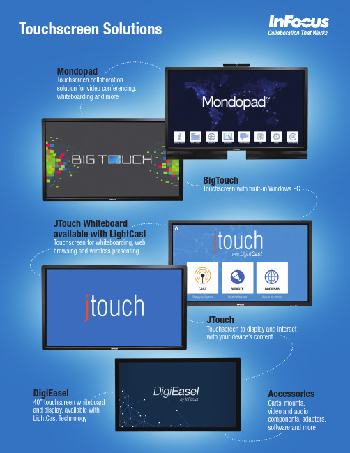
MondopadAccessoriesDigiEaselBigTouchJTouch Whiteboard available with LightCastJTouchwith your device’s contentIn-room and remote visual collaboration made easyInFocus Mondopad elegantly blends video calling,whiteboarding and more into one giant touchscreen PC for efficient face-to-face collaboration with people in any location.Bridge communication gaps, strengthen teams, capture and share information, and save time and money. You’ll never want to meet without it.• Big, bright, high-resolution touch display everyone in the room can see • Native HD video calling and data sharing that’s crystal clear • Interactive whiteboard and on-screen annotation •Built on a fast and flexible i7-based Windows PCSpecifications*Camera and microphonesResolution: 1280 × 720Frame rate: 30 fpsLens and Field of View: 70° horizontal, 56° vertical, 1.6x zoom Audio support: 3 built-in unidirectional microphones Interface: USB 3.0Tilt: Manual up/down and left/right ±40°SoundbarsPower: 100 – 240 volts AC, 50 – 60HzSpeaker Drivers (L&R): Two 3” and one 3/4” Aluminum Neodymium Tweeter (per side)Power Output (RMS): 25 watts/channel @ 1% THD, 1KHz, 2-channels drive, 70 watts total system PEAK Frequency Response: 90 Hz to 20 KHzSystemProduct WeightINF5720: 139.5 lbs / 63.3 kg INF7021: 170 lbs / 77.1 kgProduct Dimensions (W x D x H)INF5720: 56.7 x 3.7 x 40.7 in / 1388 x 91 x 998 mm INF7021: 65.7 x 4 x 45 in / 1669 x 102 x 1143 mmAccessories Included †: Wireless keyboard (where allowed),wireless mouse (where allowed), stylus, VGA cable, USB cable, security screws, security screw removal tool, power cord, remote, quick setup guide, sound bar assembly, camera assembly, foot assembly (feet not included with INF7021)Warranty: 1 year limited, extended warranties available Software Maintenance Plan: 1 year of softwareupgrades. Software maintenance extensions plans available.Power Consumption: INF5720: 250W max INF7021: 275W maxLearn more about Mondopad at /mondopadVideo Connect to the WorldBring people together to collaborate anytime without expensive travel, while still achieving the benefits of face-to-face interaction.• Make and receive video calls right away with free InFocus 121 Basic video calling service for the first year• Conduct instant 4-way conversations when you upgrade to InFocus 121 Premium video calling service• If you have a video conference server or service, add Mondopad as a SIP endpoint or install the desktop client onto MondopadWhiteboard and AnnotationWhiteboard and annotation apps make it easy to brainstorm and capture and share ideas.• Create a whiteboard on a canvas of up to 100 display screens in size• Quickly and easily take notes on presentations, web pages, videos and more • Save and email your drawings to meeting participants from the MondopadBring Your Own DeviceSecurely connect and share content with Mondopad from PCs, Macs, Chromebooks,tablets or smartphones and make meetings more collaborative, productive and sustainable.• Wirelessly cast your device’s screen to the Mondopad• Control the Mondopad with your device, such as advancing slides or annotating • People can video-call your Mondopad from a computer, tablet or smartphone70˝57˝The touch PC that d emands an audienceBigTouch combines the fun of a tablet with the productivity of a PC in a giant, fast, and fluid touch experience for your shared work space.• Run all your Windows apps in touch mode• Highly customizable for your needs and your PC applications • Intel Core i7 processor with fast solid state hard drive •Wireless mouse and keyboard includedSystemProduct WeightINF5711: 125.5 lbs / 57 kg INF7011: 155 lbs / 70.3 kg INF8012: 175 lbs / 79.4 kgProduct Dimensions (W x D x H)INF5711: 56.7 x 3.7 x 34.9 in / 1388 x 91 x 856 mm INF7011: 65.7 x 4 x 41 in / 1669 x 102 x 1041 mm INF8012: 74.8 x 4 x 46.3 in / 1900 x 101 x 1176 mm Accessories Included †: Wireless keyboard (where allowed), wireless mouse (where allowed), cleaning cloth, VGA cable, USB cable, security screws with removal tool, power cord, remote control, quick setup guide, feet/table stand assembly (feet not included with INF7011 or INF8012)Warranty: 1 year limited, extended warranties available Operating Temperature: 41 to 95°F at 0 to 10K ft / 5 to 35°C at 0 to 3,048 mNoise: <40dBA @ 77°F / 25°C Power Consumption: INF5711: 250W max INF7011: 275W max INF8012: 350W max Energy Star: 5.1 for PCThe Tablet Experience…MagnifiedTablets are fun. Touch is intuitive. The InFocus BigTouch employs a beautiful 57-inch, 70-inch or 80-inch display that allows that enjoyable experience, and your content, to be seen and shared.• Brilliant 4K (80” model) or 1080p HD (70” and 57” models) displays show off your content with incredible brightness, color and clarity• Multiple point touchscreen uses four sensors, one in each corner of the screen, to deliver exceptionally accurate touches, swipes and gestures• Windows gestures such as tap, slide, swipe, pinch, and rotate can be used to get a global view of everything on t he screen and slide back and forth to find what you’re looking for• Wireless keyboard and mouse also included to easily control the display from your seatWhiteboard Like a Pro (optional)Add our optional BigNote whiteboarding software to turn your BigTouch into a full-featured digital whiteboard with document annotation • Wide assortment of pens, colors and shapes • Whiteboard on up to 10 square feet of space • Annotate on screen and save the changes• BigNote files are cross-compatible with Mondopad’s whiteboard appThe Power of a PC at Your FingertipsMaximize the touch experience on a large scale by adding the power of a PC withthe InFocus BigTouch.• Use the multiple point touch display with intuitive Windows gestures to interact with your content• Personalize the Start screen with tiles that connect to a person, app, website, folder or whatever else is i mportant to you • Familiar Windows desktop that you’ve used before• Use your apps, get more apps in the Windows Store, and arrangethem any way you want• Multi-task by snapping two apps side-by-side•Enhanced features to easily connect to your networks, access filesin the cloud, encrypt data, and moreSpecifications*80˝70˝57˝Learn more about BigTouch at /bigtouch** North America onlyDraw or write on a turn-key interactive whiteboard. Upgrade your display with LightCast Technology to add wireless content sharing and web browsing.• 1080p display with multiple-point touch interactivity • Built-in, full-featured digital whiteboard• Display a mobile device wirelessly (Wireless Collaboration models only)• Access the Internet with the built-in web browser (Wireless Collaboration models only)•Enable touch from your computer using the 4-port USB hubInteractive WhiteboardDraw, write, and capture notes.• Capture and save whiteboard notes electronically• Email information directly from the JTouch (LightCast models only)• Write or draw with complete collection of pens, highlighters, shapes, lines and colors • Paste backgrounds and images onto a whiteboard or wallpaper the entire canvasCapacitive TouchThe ultra-responsive technology found in tablets and smart phones is now in your display (INF6502WB).• Multiple point capacitive touch• Works seamlessly with finger, stylus, and medical grade gloves • Sleek, bezel-less technologyWireless CollaborationMake meetings and lessons of all types more efficient and engaging with the wireless collaboration solution from InFocus. Easily connect and share content from any mobile device without wires or cords. • Robust and reliable connection via special apps with extra features: - Annotation from your smartphone or tablet mobile device - Built-in support for cloud drive services- Use your device’s camera as a document camera • See content from four devices at once with QuadView• The Moderator feature empowers teachers to control a classroom full of student devices and choose who is presenting• The Follow feature lets the audience follow along with the presented content from their own device• Connect natively with AirPlay or Miracast, or via Chrome extension• On-board video decoding displays HD video seamlessly, even at high resolutions •Connect to your network to create a new, secure wireless access pointSystemAccessories Included: Power cord, VGA cable, USB Type-A to Type-B cable,remote control, user documentationWarranty: 2 years Product Weight:INF6501w / INF6501wp / INF6501wAG/ INF6501wAGp / INF6501CB/ INF6501CBp / INF6501CBAGp /INF6501CBAGp: 110.2 lbs. / 50.1 kgINF6502WB / INF6502WBp /INF6502WBAG / INF6502WBAGp:117.9 lbs. / 53.5 kgProduct Dimensions: INF6501w / INF6501wp / INF6501wAG/ INF6501wAGp / INF6501CB/INF6501CBp / INF6501CBAG / INF6501CBAGp: 36.4 x 60.2 x 3.3 in. / 925 x 1529 x 84mmINF6502WB / INF6502WBp / INF6502WBAG / INF6502WBAGp: 59.9 in. x 35.3 x 3.3 in /1520.5 x 895.5 x 83.1 mm Operating Conditions:32 to 104° at 0 to 10K feet/ 0 to 40° at 0 to 3,048 mNoise: < 40dBA at 77° F / 25° CPower Consumption:INF6501w / INF6501wp / INF6501wAG / INF6501wAGp / INF6501CB /INF6501CBp / INF6501CBAGp /INF6501CBAGp: 210W INF6502WB / INF6502WBp / INF6502WBAG / INF6502WBAGp: TBD65” JTouch Whiteboard with LightCast (INF6501CB/INF6501CBp)Learn more about JTouch at /jtouchWhiteboard, with availableWireless CollaborationSpecifications*Large touchscreen displays to engage your audience and fit your budgetThe InFocus JTouch combines precise touchscreen t echnology with a bright, colorful LCD display to engage audiences in classrooms, boardrooms, and beyond.• Giant, high resolution touch display for a great price• Incredibly sharp 4K resolution now available for 80-inch model • 70-inch and 57-inch models offer bright, vivid 1080p HD resolution • Run all your Windows apps, even the older ones, in touch mode • Your content will be interactive, bright and crisp in any light • Accurate and responsive touch overlay with multi-touch capability •Multiple ways to quickly connect and display your notebookSystemAccessories Included: Power cord, remote control, user guide Warranty:INF5701: 2 YearINF7001a/INF7001ap: 2 Year INF8002: 1 Year Product Weight:INF5701: 124 lbs / 56.4 kgINF7001a/INF7001ap: 154 lbs / 70 kg INF8002: 173 lbs / 78.5 kg Product Dimensions:INF5701: 34.9 x 56.7 x 3.7 in. / 886 x 1440 x 94 mmINF7001a/INF7001ap: 65.7 x 4 x 39 in / 1669 x 102 x 991 mm INF8002: 74.8 x 4 x 46.3 in / 1900 x 101 x 1176 mm Operating Conditions: 41 to 95°F at 0 to 10K ft / 5 to 35°C at 0 to 3,048 m Noise: <40dBA @ 77° F / 25°C Power Consumption: INF5701: 250W maxINF7001a/INF7001ap: 275W max INF8002: 350W max80˝70˝57˝** North America onlyCapture your ideas whenever and wherever they occurDraw, write, and capture notes or share your device’s screen on DigiEasel’s bright, colorful 40” touch display—all at an unbeatable price.• Beautiful 1080p capacitive touch display in portrait or landscape orientation • Draw on a massive whiteboard canvas and save and share the results • Multiple colors, shapes, and backgrounds are available to help youcommunicate your ideas• Wirelessly display your device’s screen or browse the web (INF4030CB/INF4030CBp only)• Display your notebook via HDMI, VGA, or component videoUse It AnywhereGreat ideas and conversations can happen anywhere, anytime. Be ready to capturethat information with DigiEasel. At 40 inches, DigiEasel is our most versatile interactive whiteboard and display. Choose from portrait or landscape mode to fit the need of any boardroom, classroom, huddle space—or anywhere you collaborate.Get the Most Out of Your WhiteboardStop taking photos of your old dry erase board and step up to a digital whiteboard. You’ll never lose an idea and your meetings will be more efficient and productive.•Capture and save whiteboard notes electronically•The whiteboard scrolls seamlessly as you need additional space, allowing room for free-form drawings, diagrams, and notes•Use it with or without a stylus•10-point touch allows multiple people to write or draw at the same time•No calibration required Wireless CollaborationMake meetings and lessons of all types more efficient and engaging with the wireless collaboration solution from InFocus. Easily connect and share content from any mobile device without wires or cords.•Robust and reliable connection via special apps with extra features:- Annotation from your smartphone or tablet mobile device- Built-in support for cloud drive services- Use your device’s camera as a document camera• See content from four devices at once with QuadView•The Moderator feature empowers teachers to control a classroom full of student devices and choose who is presenting•The Follow feature lets the audience follow along with the presented content from their own device•Connect natively with AirPlay or Miracast, or via Chrome extension•On-board video decoding displays HD video seamlessly, even at high resolutions •Connect to your network to create a new, secure wireless access point Interactive Digital SignageImpress customers and visitors with a professional interactive sign to promote your products, share news, give direction, and more. Use Sign Manager software to display your interactive signage on DigiEasel—in a variety of environments, including offices,education, or retail.DigiEasel works in either portrait or landscape mode.SystemAccessories Included: Power cord,VGA cable, USB cable, tray, stylus,and documentationWarranty: 1 YearProduct Weight: 44 lbs / 20.0 kgProduct Dimensions: 38.3 x 21.8 x 4.5 in. /974 x 553 x 113 mmOperating Conditions: 32° to 104° F at 0 to10K feet / 0° to 40° at 0 to 3,048 mNoise:< 40dBA at 77° F / 25° CLearn more about DigiEasel at /displays/DigiEasel-SeriesInFocus Touch Display ComparisonIdeal Use Case ScenariosMondopadBigTouchJTouch WhiteboardJTouch DigiEaselPC Built-InP(Windows 7)P(Windows 8 or Windows 10)CustomNoCustomWebcam, microphone, and speaker barP Optional No No NoVideoconferencing softwareP Optional(InFocus BigConnectSoftware)No No NoMicrosoft Office P Optional(Purchase via Microsoft)No NoNoWhiteboardP Optional(InFocus BigNote Software)POptional(BigNote Software installedon your PC)PLightCast-enabled Wireless Casting and BrowserPNoAvailable in select modelsNoAvailable in select models65" JTouch with Wireless Collaboration (INF6501CB/INF6501CBp)70" Mondopad (INF7021)80" JTouch (INF8002)40" DigiEasel (INF4030/INF4030p)Works withJTouch Audio and VideoMondopadBigTouchw/Wireless CollaborationJTouchDigiEaselPart NumberRealCam Pan/Tilt/Zoom Camera- True HD 1080p resolution- Pan/tilt/zoom control with included remotePP N/A N/A N/A INA-PTZ-3Camera and Microphone Array - 720p camera with 3 built-in microphones - Manual tilt up/down and left/rightIncludedP N/A N/A N/A HW-CAMERA-2Thunder Speakerphone - Tabletop speaker and microphone for Mondopad or other communication device P PN/A N/A N/A INA-TH150SIP2Phone- Mondopad audio bridge/adapter for an analog speakerphoneP N/A N/A N/A N/A INASIP2PHONEMondopad Polycom Conference Link Cable - Turns a Polycom speakerphone into the microphone and speakers for a MondopadPN/AN/A N/AN/A INF-POLYCBLESoundbars- Two 25-watt stereo soundbars tuned for voice and multi-media IncludedP N/AP N/AHW-SOUNDBAR-4Carts and MountsLarge Mobile Cart - Adjustable cart on wheels for easy mobility - Fits any size displayP P P P N/A INF-MCART-PL Pro Mobile Cart- Adjustable cart on wheels for easy mobility - Fits 57-inch, 65-inch and 70-inch modelsP P P P N/A INF-MOBCARTPRO-B (Black) INF-MOBCARTPRO-S (Silver)Deluxe Mobile Cart -Adjustable cart on wheels for 57", 65", 70" or 80" display -Includes PTZ camera mount and accessories shelf P P P P N/A INA-MCARTDX Mobile Cart - Adjustable cart on wheels for a 57", 65" or 70" display P P P P N/A INF-MOBCART Floor Stand- Height adjustment: 4 - 6 feetPPPPN/AINF-FLRSTND DigiEasel Floor Stand - Stand for 40-inch DigiEasel display N/AN/AN/AN/APINA-STNDSM Large Wall Mount - Adjustable wall mount for any size displayP P P P N/AINF-WALLMNT3Wall Mount- Adjustable wall mount for 40", 57", 65" or 70" displayP P P P PINF-WALLMNT2Lift Assist Mounts- Raise and lower the display with spring-assisted ease - Wall mount and mobile cart options for any size displayPP PPN/AINA-MNTBB70,INA-MNTBB95, INA-CARTBB, INA-SUPPORTBB, INA-VESABBSoftwareBigConnect Video Calling Software - Make video calls from your PC to other SIP end pointsFunctionality included P N/A N/AN/A INS-BCONNECTBigNote Whiteboard Software- Add whiteboard and annotation functionality to a BigTouch or other PC - Pens, highlighters, shapes and lines in multiple colorsFunctionality included P Functionality includedPFunctionality includedINS-BIGNOTEBigTouch-to-Mondopad Upgrade- Add Mondopad software and Microsoft Office to a BigTouchFunctionality includedPN/AN/AN/AINSMPWIN8SWServices121 Video Calling- 121 Basic service for video calling between two devices- 121 Premium service to add 4-way video calling and custom SIP address - 1-, 2-, and 3-year optionsP N/AN/A N/A N/A8 SKUsConX Video Meeting- Host cloud-based video meetings that people can joinfrom any SIP or H.323 device, web browser or audio-only phone - 6-, 12-, or 25-participant options - 1-, 2- or 3-year optionsP N/A N/A N/A N/A9 SKUsTraining Services- 2 hours or 4 hours of virtual training to help get the most from Mondopad and video conferencing services P N/A N/A N/A N/AINF-VT2 (2-hour) INF-VT4 (4-hour)WarrantiesExtended Hardware Warranties - Extends the warranty of the touch panel by 1 or 2 yearsP PPPP12 SKUs Software Maintenance Plans- 1- or 2-year plans to ensure you have the most up-to-date Mondopad softwareP N/AN/A N/A N/A EPWSOFTPLAN1EPWSOFTPLAN2Premier Coverage Plans (hardware and software)- Extended hardware warranty and software maintenance plans for 1 or 2 yearsPPN/AN/AN/A10 SKUsAccessories for Touch Displays* Product specifications, terms, and offerings are subject to change at any time without notice.†Keyboard and/or mouse may not be shipped to all countries.(except 65-inch)。
Omega 超低温数据记录器产品说明书

OM-CP-CRYO-TEMP, $199, shown actual size.
OM-CP-IFC300 docking station, 2 m (6') USB cable and Windows® software, $70, sold separately and required to operate data logger. Shown actual size.
Password Protection: An optional password may be programmed into the device to restrict access to configuration options; data may be read out without the password Calibration: Digital calibration is available to the user through software Calibration Date: Automatically recorded within device Power: 3.6V lithium battery (included), factory replaceable only Battery Life:
AVAILABLE FOR FAST DELIVERY!
To Order (Specify Model Number)
Model No.
Price Description
OM-CP-CRYO-TEMP
$199 Ultra-low temperature data logger
OM-CP-CRYO-TEMP-CERT 259 Ultra-low temperature data logger with NIST calibration certificate
IC datasheet pdf-CD54AC273, CD74AC273,CD54ACT273, CD74ACT273,pdf(Octal D Flip-Flop)
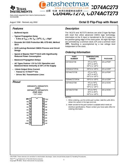
Data sheet acquired from Harris SemiconductorSCHS249BFeatures•Buffered Inputs•Typical Propagation Delay- 6.5ns at V CC = 5V , T A = 25o C, C L = 50pF•Exceeds 2kV ESD Protection MIL-STD-883, Method 3015•SCR-Latchup-Resistant CMOS Process and Circuit Design •Speed of Bipolar FAST™/AS/S with Significantly Reduced Power Consumption •Balanced Propagation Delays•AC Types Feature 1.5V to 5.5V Operation and Balanced Noise Immunity at 30% of the Supply •±24mA Output Drive Current -Fanout to 15 FAST™ ICs-Drives 50Ω Transmission LinesPinoutCD54AC273, CD54ACT273(CDIP)CD74AC273, CD74ACT273(PDIP , SOIC)TOP VIEWDescriptionThe ’AC273and ’ACT273devices are octal D-type flip-flops with reset that utilize advanced CMOS logic rmation at the D input is transferred to the Q output on the positive-going edge of the clock pulse.All eight flip-flops are controlled by a common clock (CP)and a common reset (MR).Resetting is accomplished by a low voltage level independent of the clock.1112131415161718201910987654321MR Q0D0D1Q1Q2D3D2Q3GND V CC D7D6Q6Q7Q5D5D4Q4CPOrdering InformationPART NUMBER TEMPERATURERANGE PACKAGE CD74AC273E0o C to 70o C -40o C to 85o C -55o C to 125o C 20 Ld PDIPCD54AC273F3A -55o C to 125o C 20 Ld CDIP CD74ACT273E0o C to 70o C -40o C to 85o C -55o C to 125o C 20 Ld PDIPCD54ACT273F3A -55o C to 125o C 20 Ld CDIP CD74AC273M0o C to 70o C -40o C to 85o C -55o C to 125o C 20 Ld SOICCD74ACT273M 0o C to 70o C -40o C to 85o C -55o C to 125o C20 Ld SOICNOTES:1.When ordering,use the entire part number.Add the suffix 96to obtain the variant in the tape and reel.2.Wafer and die for this part number is available which meets allelectrical specifications.Please contact your local sales office for ordering information.August 1998 - Revised July 2002CD54AC273, CD74AC273CD54ACT273, CD74ACT273Octal D Flip-Flop with ResetFunctional DiagramTRUTH TABLE INPUTSOUTPUTSRESET (MR)CLOCK CP DATA Dn Qn L X X L H ↑H H H ↑L L HLXQ0H =High level (steady state),L =Low level (steady state),X =Irrel-evant,↑=Transition from Low to High level,Q0=The level of Q before the indicated steady-state input conditions were estab-lished.Q0Q1Q2Q3Q4Q5Q6Q7RESET MRD0D1D2D3D4D5D6D7CLOCKCPDATA INPUTSDATAOUTPUTSAbsolute Maximum Ratings Thermal InformationDC Supply Voltage, V CC. . . . . . . . . . . . . . . . . . . . . . . .-0.5V to 6V DC Input Diode Current, I IKFor V I < -0.5V or V I > V CC + 0.5V. . . . . . . . . . . . . . . . . . . . . .±20mA DC Output Diode Current, I OKFor V O < -0.5V or V O > V CC + 0.5V . . . . . . . . . . . . . . . . . . . .±50mA DC Output Source or Sink Current per Output Pin, I OFor V O > -0.5V or V O < V CC + 0.5V . . . . . . . . . . . . . . . . . . . .±50mA DC V CC or Ground Current, I CC or I GND (Note 3) . . . . . . . . .±100mA Operating ConditionsTemperature Range, T A . . . . . . . . . . . . . . . . . . . . . .-55o C to 125o C Supply Voltage Range, V CC (Note 4)AC T ypes. . . . . . . . . . . . . . . . . . . . . . . . . . . . . . . . . . .1.5V to 5.5V ACT T ypes . . . . . . . . . . . . . . . . . . . . . . . . . . . . . . . . .4.5V to 5.5V DC Input or Output Voltage, V I, V O . . . . . . . . . . . . . . . . .0V to V CC Input Rise and Fall Slew Rate, dt/dvAC T ypes, 1.5V to 3V . . . . . . . . . . . . . . . . . . . . . . . . .50ns (Max) AC T ypes, 3.6V to 5.5V. . . . . . . . . . . . . . . . . . . . . . . .20ns (Max) ACT T ypes, 4.5V to 5.5V. . . . . . . . . . . . . . . . . . . . . . .10ns (Max)Thermal Resistance,θJA(Typical, Note 5)E Package. . . . . . . . . . . . . . . . . . . . . . . . . . . . . . . . . . . . .69o C/W M Package. . . . . . . . . . . . . . . . . . . . . . . . . . . . . . . . . . . . .58o C/W Maximum Junction T emperature (Plastic Package) . . . . . . . . . .150o C Maximum Storage Temperature Range . . . . . . . . . .-65o C to 150o C Maximum Lead Temperature (Soldering 10s). . . . . . . . . . . . .300o CCAUTION:Stresses above those listed in“Absolute Maximum Ratings”may cause permanent damage to the device.This is a stress only rating and operation of the device at these or any other conditions above those indicated in the operational sections of this specification is not implied.NOTES:3.For up to 4 outputs per device, add±25mA for each additional output.4.Unless otherwise specified, all voltages are referenced to ground.5.The package thermal impedance is calculated in accordance with JESD 51.DC Electrical SpecificationsPARAMETER SYMBOLTESTCONDITIONS VCC(V)25o C-40o C TO85o C-55o C TO125o CUNITS V I(V)I O(mA)MIN MAX MIN MAX MIN MAXAC TYPESHigh Level Input Voltage V IH-- 1.5 1.2- 1.2- 1.2-V3 2.1- 2.1- 2.1-V5.5 3.85- 3.85- 3.85-V Low Level Input Voltage V IL-- 1.5-0.3-0.3-0.3V3-0.9-0.9-0.9V5.5- 1.65- 1.65- 1.65V High Level Output Voltage V OH V IH or V IL-0.05 1.5 1.4- 1.4- 1.4-V-0.053 2.9- 2.9- 2.9-V-0.05 4.5 4.4- 4.4- 4.4-V-43 2.58- 2.48- 2.4-V-24 4.5 3.94- 3.8- 3.7-V-75(Note 6, 7)5.5-- 3.85---V-50(Note 6, 7)5.5---- 3.85-VLow Level Output VoltageV OLV IH or V IL0.05 1.5-0.1-0.1-0.1V 0.053-0.1-0.1-0.1V 0.05 4.5-0.1-0.1-0.1V 123-0.36-0.44-0.5V 24 4.5-0.36-0.44-0.5V 75(Note 6, 7) 5.5--- 1.65--V 50(Note 6, 7)5.5----- 1.65V Input Leakage Current I I V CC or GND - 5.5-±0.1-±1-±1µA Quiescent Supply Current MSI I CCV CC or GND5.5-8-80-160µAACT TYPESHigh Level Input Voltage V IH -- 4.5 to 5.52-2-2-V Low Level Input Voltage V IL -- 4.5 to 5.5-0.8-0.8-0.8V High Level Output VoltageV OHV IH or V IL-0.05 4.5 4.4- 4.4- 4.4-V -24 4.5 3.94- 3.8- 3.7-V -75(Note 6, 7) 5.5-- 3.85---V -50(Note 6, 7)5.5---- 3.85-V Low Level Output VoltageV OLV IH or V IL0.05 4.5-0.1-0.1-0.1V 24 4.5-0.36-0.44-0.5V 75(Note 6, 7) 5.5--- 1.65--V 50(Note 6, 7)5.5----- 1.65V Input Leakage Current I I V CC or GND - 5.5-±0.1-±1-±1µA Quiescent Supply Current MSII CC V CC or GND 0 5.5-8-80-160µA Additional Supply Current per Input Pin TTL Inputs High 1 Unit Load ∆I CCV CC -2.1- 4.5 to 5.5- 2.4- 2.8-3mANOTES:6.Test one output at a time for a 1-second maximum duration.Measurement is made by forcing current and measuring voltage to minimize power dissipation.7.Test verifies a minimum 50Ω transmission-line-drive capability at 85o C, 75Ω at 125o C.ACT Input Load TableINPUT UNIT LOADDn 0.5MR 0.57CP1NOTE:Unit load is ∆I CC limit specified in DC Electrical Specifications T able, e.g., 2.4mA max at 25o C.DC Electrical Specifications(Continued)PARAMETERSYMBOL TEST CONDITIONSV CC (V)25o C -40o C TO 85o C -55o C TO 125o C UNITS V I (V)I O (mA)MIN MAX MIN MAX MIN MAXPrerequisite For Switching FunctionPARAMETER SYMBOL V CC (V)-40o C TO 85o C-55o C TO 125o CUNITS MIN MAX MIN MAXAC TYPESData to CP Set-Up Time t SU 1.52-2-ns3.3(Note 9)2-2-ns5(Note 10)2-2-ns Hold Time t H 1.52-2-ns3.32-2-ns52-2-ns Removal Time,MR to CP t REM 1.52-2-ns3.32-2-ns52-2-ns MR Pulse Width t W 1.555-63-ns3.3 6.1-7-ns5 4.4-5-ns CP Pulse Width t W 1.555-63-ns3.3 6.1-7-ns5 4.4-5-ns CP Frequency f MAX 1.59-8-MHz3.381-71-MHz5114-100-MHz ACT TYPESData to CP Set-Up Time t SU5(Note 10)2-2-ns Hold Time t H52-2-ns Removal Time MR to CP t REM52-2-ns MR Pulse Width t W5 4.4-5-ns CP Pulse Width t W5 5.3-6-ns CP Frequency f MAX597-85-MHz Switching Specifications Input t r, t f = 3ns, C L= 50pF (Worst Case)PARAMETER SYMBOL V CC (V)-40o C TO 85o C-55o C TO 125o CUNITS MIN TYP MAX MIN TYP MAXAC TYPESPropagation Delay, CP to Qn t PLH, t PHL 1.5--154--169ns3.3(Note 9)4.9-17.2 4.7-18.9ns5(Note 10)3.5-12.3 3.4-13.5nsPropagation Delay,MR to Qnt PLH , t PHL1.5--154--169ns 3.3 4.9-17.2 4.7-18.9ns 53.5-12.3 3.4-13.5ns Input CapacitanceC I ---10--10pF Power Dissipation Capacitance C PD (Note 11)--45--45-pFACT TYPES Propagation Delay,CP to Qnt PLH , t PHL 5(Note 10)3.5-12.3 3.4-13.5ns Propagation Delay,MR to Qn t PLH , t PHL5 3.5-12.3 3.4-13.5ns Input CapacitanceC I ---10--10pF Power Dissipation Capacitance C PD (Note 11)--45--45-pFNOTES:8.Limits tested 100%.9.3.3V Min is at 3.6V, Max is at 3V.10.5V Min is at 5.5V, Max is at 4.5V.11.C PD is used to determine the dynamic power consumption per flip-flop.AC: P D = C PD V CC 2 f i =∑ (C L V CC 2 f o )ACT:P D =C PD V CC 2f i +∑(C L V CC 2f o )+V CC ∆I CC where f i =input frequency,f o =output frequency,C L =output load capacitance,V CC = supply voltage.FIGURE 1.PROPAGATION DELAY TIMES AND CLOCKPULSE WIDTH FIGURE 2.PREREQUISITE AND PROPAGATION DELAYTIMES FOR MASTER RESETSwitching Specifications Input t r , t f = 3ns, C L = 50pF (Worst Case)(Continued)PARAMETERSYMBOL V CC (V)-40o C TO 85o C-55o C TO 125o CUNITS MIN TYP MAX MIN TYP MAX 90%t f t r V SV S V SV SV St PLHt PHLt W 10%10%CP INPUT LEVEL QMR CPINPUT LEVELV SQV St REMV SV St PLHt WGNDINPUT(Q)FIGURE 3.PREREQUISITE FOR CLOCKDV S V S V SV S V S V St H (H)t SU (L)t H (L)t SU (H)CPOUTPUT LEVELDUT OUTPUTR L (NOTE)OUTPUT LOAD500ΩC L 50pFNOTE:For AC Series Only: When V CC = 1.5V , R L = 1k Ω.FIGURE 4.PROPAGATION DELAY TIMESACACT Input LevelV CC 3V Input Switching Voltage, V S 0.5 V CC 1.5V Output Switching Voltage, V S0.5 V CC0.5 V CCPACKAGING INFORMATIONOrderable Device Status(1)PackageType PackageDrawingPins PackageQtyEco Plan(2)Lead/Ball Finish MSL Peak Temp(3)CD54AC273F3A ACTIVE CDIP J201TBD A42N/A for Pkg Type CD54ACT273F3A ACTIVE CDIP J201TBD A42N/A for Pkg Type CD74AC273E ACTIVE PDIP N2020Pb-Free(RoHS)CU NIPDAU N/A for Pkg TypeCD74AC273EE4ACTIVE PDIP N2020Pb-Free(RoHS)CU NIPDAU N/A for Pkg TypeCD74AC273M ACTIVE SOIC DW2025Green(RoHS&no Sb/Br)CU NIPDAU Level-1-260C-UNLIMCD74AC273M96ACTIVE SOIC DW202000Green(RoHS&no Sb/Br)CU NIPDAU Level-1-260C-UNLIMCD74AC273M96E4ACTIVE SOIC DW202000Green(RoHS&no Sb/Br)CU NIPDAU Level-1-260C-UNLIMCD74AC273M96G4ACTIVE SOIC DW202000Green(RoHS&no Sb/Br)CU NIPDAU Level-1-260C-UNLIMCD74AC273ME4ACTIVE SOIC DW2025Green(RoHS&no Sb/Br)CU NIPDAU Level-1-260C-UNLIMCD74AC273MG4ACTIVE SOIC DW2025Green(RoHS&no Sb/Br)CU NIPDAU Level-1-260C-UNLIMCD74ACT273E ACTIVE PDIP N2020Pb-Free(RoHS)CU NIPDAU N/A for Pkg TypeCD74ACT273EE4ACTIVE PDIP N2020Pb-Free(RoHS)CU NIPDAU N/A for Pkg TypeCD74ACT273M ACTIVE SOIC DW2025Green(RoHS&no Sb/Br)CU NIPDAU Level-1-260C-UNLIMCD74ACT273M96ACTIVE SOIC DW202000Green(RoHS&no Sb/Br)CU NIPDAU Level-1-260C-UNLIMCD74ACT273M96E4ACTIVE SOIC DW202000Green(RoHS&no Sb/Br)CU NIPDAU Level-1-260C-UNLIMCD74ACT273M96G4ACTIVE SOIC DW202000Green(RoHS&no Sb/Br)CU NIPDAU Level-1-260C-UNLIMCD74ACT273ME4ACTIVE SOIC DW2025Green(RoHS&no Sb/Br)CU NIPDAU Level-1-260C-UNLIMCD74ACT273MG4ACTIVE SOIC DW2025Green(RoHS&no Sb/Br)CU NIPDAU Level-1-260C-UNLIMCD74ACT273PW ACTIVE TSSOP PW2070Green(RoHS&no Sb/Br)CU NIPDAU Level-1-260C-UNLIMCD74ACT273PWE4ACTIVE TSSOP PW2070Green(RoHS&no Sb/Br)CU NIPDAU Level-1-260C-UNLIMCD74ACT273PWG4ACTIVE TSSOP PW2070Green(RoHS&no Sb/Br)CU NIPDAU Level-1-260C-UNLIMCD74ACT273PWR ACTIVE TSSOP PW202000Green(RoHS&no Sb/Br)CU NIPDAU Level-1-260C-UNLIMCD74ACT273PWRE4ACTIVE TSSOP PW202000Green(RoHS&no Sb/Br)CU NIPDAU Level-1-260C-UNLIMCD74ACT273PWRG4ACTIVE TSSOP PW202000Green(RoHS&no Sb/Br)CU NIPDAU Level-1-260C-UNLIMCD74ACT273SM96ACTIVE SSOP DB202000Green(RoHS&no Sb/Br)CU NIPDAU Level-1-260C-UNLIMCD74ACT273SM96E4ACTIVE SSOP DB202000Green(RoHS&CU NIPDAU Level-1-260C-UNLIMOrderable Device Status(1)PackageType PackageDrawingPins PackageQtyEco Plan(2)Lead/Ball Finish MSL Peak Temp(3)no Sb/Br)CD74ACT273SM96G4ACTIVE SSOP DB202000Green(RoHS&no Sb/Br)CU NIPDAU Level-1-260C-UNLIM(1)The marketing status values are defined as follows:ACTIVE:Product device recommended for new designs.LIFEBUY:TI has announced that the device will be discontinued,and a lifetime-buy period is in effect.NRND:Not recommended for new designs.Device is in production to support existing customers,but TI does not recommend using this part in a new design.PREVIEW:Device has been announced but is not in production.Samples may or may not be available.OBSOLETE:TI has discontinued the production of the device.(2)Eco Plan-The planned eco-friendly classification:Pb-Free(RoHS),Pb-Free(RoHS Exempt),or Green(RoHS&no Sb/Br)-please check /productcontent for the latest availability information and additional product content details.TBD:The Pb-Free/Green conversion plan has not been defined.Pb-Free(RoHS):TI's terms"Lead-Free"or"Pb-Free"mean semiconductor products that are compatible with the current RoHS requirements for all6substances,including the requirement that lead not exceed0.1%by weight in homogeneous materials.Where designed to be soldered at high temperatures,TI Pb-Free products are suitable for use in specified lead-free processes.Pb-Free(RoHS Exempt):This component has a RoHS exemption for either1)lead-based flip-chip solder bumps used between the die and package,or2)lead-based die adhesive used between the die and leadframe.The component is otherwise considered Pb-Free(RoHS compatible)as defined above.Green(RoHS&no Sb/Br):TI defines"Green"to mean Pb-Free(RoHS compatible),and free of Bromine(Br)and Antimony(Sb)based flame retardants(Br or Sb do not exceed0.1%by weight in homogeneous material)(3)MSL,Peak Temp.--The Moisture Sensitivity Level rating according to the JEDEC industry standard classifications,and peak solder temperature.Important Information and Disclaimer:The information provided on this page represents TI's knowledge and belief as of the date that it is provided.TI bases its knowledge and belief on information provided by third parties,and makes no representation or warranty as to the accuracy of such information.Efforts are underway to better integrate information from third parties.TI has taken and continues to take reasonable steps to provide representative and accurate information but may not have conducted destructive testing or chemical analysis on incoming materials and chemicals.TI and TI suppliers consider certain information to be proprietary,and thus CAS numbers and other limited information may not be available for release.In no event shall TI's liability arising out of such information exceed the total purchase price of the TI part(s)at issue in this document sold by TI to Customer on an annual basis.TAPE AND REELINFORMATION*All dimensionsare nominalDevicePackage Type Package Drawing Pins SPQReel Diameter (mm)Reel Width W1(mm)A0(mm)B0(mm)K0(mm)P1(mm)W (mm)Pin1Quadrant CD74AC273M96SOIC DW 202000330.024.410.813.0 2.712.024.0Q1CD74ACT273M96SOIC DW 202000330.024.410.813.0 2.712.024.0Q1CD74ACT273PWR TSSOP PW 202000330.016.4 6.957.1 1.68.016.0Q1CD74ACT273SM96SSOPDB202000330.016.48.27.52.512.016.0Q1PACKAGE MATERIALS INFORMATION11-Mar-2008*Alldimensions are nominal DevicePackage Type Package Drawing Pins SPQ Length (mm)Width (mm)Height (mm)CD74AC273M96SOIC DW 202000346.0346.041.0CD74ACT273M96SOIC DW 202000346.0346.041.0CD74ACT273PWRTSSOP PW 202000346.0346.033.0CD74ACT273SM96SSOP DB 202000346.0346.033.0PACKAGE MATERIALS INFORMATION 11-Mar-2008Pack Materials-Page 2IMPORTANT NOTICETexas Instruments Incorporated and its subsidiaries(TI)reserve the right to make corrections,modifications,enhancements,improvements, and other changes to its products and services at any time and to discontinue any product or service without notice.Customers should obtain the latest relevant information before placing orders and should verify that such information is current and complete.All products are sold subject to TI’s terms and conditions of sale supplied at the time of order acknowledgment.TI warrants performance of its hardware products to the specifications applicable at the time of sale in accordance with TI’s standard warranty.Testing and other quality control techniques are used to the extent TI deems necessary to support this warranty.Except where mandated by government requirements,testing of all parameters of each product is not necessarily performed.TI assumes no liability for applications assistance or customer product design.Customers are responsible for their products and applications using TI components.To minimize the risks associated with customer products and applications,customers should provide adequate design and operating safeguards.TI does not warrant or represent that any license,either express or implied,is granted under any TI patent right,copyright,mask work right, or other TI intellectual property right relating to any combination,machine,or process in which TI products or services are rmation published by TI regarding third-party products or services does not constitute a license from TI to use such products or services or a warranty or endorsement e of such information may require a license from a third party under the patents or other intellectual property of the third party,or a license from TI under the patents or other intellectual property of TI.Reproduction of TI information in TI data books or data sheets is permissible only if reproduction is without alteration and is accompanied by all associated warranties,conditions,limitations,and notices.Reproduction of this information with alteration is an unfair and deceptive business practice.TI is not responsible or liable for such altered rmation of third parties may be subject to additional restrictions.Resale of TI products or services with statements different from or beyond the parameters stated by TI for that product or service voids all express and any implied warranties for the associated TI product or service and is an unfair and deceptive business practice.TI is not responsible or liable for any such statements.TI products are not authorized for use in safety-critical applications(such as life support)where a failure of the TI product would reasonably be expected to cause severe personal injury or death,unless officers of the parties have executed an agreement specifically governing such use.Buyers represent that they have all necessary expertise in the safety and regulatory ramifications of their applications,and acknowledge and agree that they are solely responsible for all legal,regulatory and safety-related requirements concerning their products and any use of TI products in such safety-critical applications,notwithstanding any applications-related information or support that may be provided by TI.Further,Buyers must fully indemnify TI and its representatives against any damages arising out of the use of TI products in such safety-critical applications.TI products are neither designed nor intended for use in military/aerospace applications or environments unless the TI products are specifically designated by TI as military-grade or"enhanced plastic."Only products designated by TI as military-grade meet military specifications.Buyers acknowledge and agree that any such use of TI products which TI has not designated as military-grade is solely at the Buyer's risk,and that they are solely responsible for compliance with all legal and regulatory requirements in connection with such use. TI products are neither designed nor intended for use in automotive applications or environments unless the specific TI products are designated by TI as compliant with ISO/TS16949requirements.Buyers acknowledge and agree that,if they use any non-designated products in automotive applications,TI will not be responsible for any failure to meet such requirements.Following are URLs where you can obtain information on other Texas Instruments products and application solutions:Products ApplicationsAmplifiers AudioData Converters AutomotiveDLP®Products BroadbandDSP Digital ControlClocks and Timers MedicalInterface MilitaryLogic Optical NetworkingPower Mgmt SecurityMicrocontrollers TelephonyRFID Video&ImagingRF/IF and ZigBee®Solutions WirelessMailing Address:Texas Instruments,Post Office Box655303,Dallas,Texas75265Copyright©2009,Texas Instruments Incorporated。
10 DOF IMU传感器 (C) 用户手册说明书

10 DOF IMU Sensor (C)User Manual 1.FeatureTable 1: Product features2.Applications●Quadcopter;●Action game controller;●Indoor inertial navigation;●Self-balancing Robot;●Altimeter;●Industrial measuring instrument.3.Interface DescriptionsTable 2: Interface descriptions4.How to useWe will illustrate the usage of the module with an example of working with a STM32 series’development board.①Download the relative codes to the development board.②Connect the development board to a PC via a serial wire, and insert the module intothe I2C 2 interface on the development board. Please take attention to theconnection between the module and I2C 2 interface, each pin of the module shouldbe connected to its corresponding port on the I2C 2 interface and FSYN pin shouldbe kept suspended respectively.Figure 1: Connection between 10 DOF IMU Sensor module and STM32③Here is the configuration of the serial port, as Table 3 shows.Baud rate 115200Data bit 8Stop bit 1Parity bit noneTable 3: Serial port configuration④After powering 10 DOF IMU Sensor on, firstly, acceleration is calibrated at horizontalstate, and magnetic is calibrated later. After done, the qualify data will output from10 DOF IMU Sensor. For detail operations as below:A.Flatting 10 DOF IMU Sensor on the horizontal position and no motion isallowed,when serial terminal received the stable data from USART1, then pressJOYSTICK button down, LED1 is flashing and both of LED2 and LED3 turn off at the mean time.B.Rotating 10 DOF IMU Sensor 180 degrees around the Z axis on the horizontalposition, when serial terminal received the stable data from USART1, then press JOYSTICK button down, LED2 is flashing and both of LED1 and LED3 turn off at the mean time.C.Inverting 10 DOF IMU Sensor on the horizontal position, means holding thebackside of 10 DOF IMU Sensor upward and the positive side downward. Then press JOYSTICK button down, LED3 turn on forever indicating that magnetic calibration is complete, and both of LED1 and LED2 turn off at the mean time.D.Rotating 10 DOF IMU Sensor 180 degrees around the Z axis on the horizontalposition,recording and comparing with the magnetic data from serial terminal before and after rotating, if equaling to each other and behaving at opposite ofdirection, as a result, magnetic calibrating is successful.⑤If succeed to calibrate, serial terminal will received the qualify data as following:⑥The serial output is as followed:Roll, Pitch, Yaw Roll angle(°), Pitch angle(°), Yaw angle(°)Acceleration Acceleration value (LSB, translatable into theunit: g)Gyroscope Acceleration value (LSB, translatable into theunit: g)Magnetic Digital compass title angle (°)Pressure Pressure value (hPa)Altitude Altitude value (m)Temperature Temperature value (℃)Table 4: The meanings of the serial output5.Parameter calibration and calculation5.1 Altitude calibrationFor your first time to use 10 DOF IMU Sensor, you may find that there is a large difference between the altitude value outputted by the module and the actual altitude. This is because10 DOF IMU Sensor calculates the pressure at sea level P0 with the Altitude of its currentposition and the measured pressure, providing that both module current position andpressure are known. And this P0 will be taken as a benchmark for subsequent calculations.For more detailed information, please refer to BST-BMP180-DS000-09.pdf:Altitude:With the benchmark P0, you can calculate the Altitude of the module current position as well.Therefore, you should firstly set the altitude of the module current position as a benchmark in the sample code 10 DOF IMU Sensor\SRC\HardWare\BMP180\ BMP180.h (normally, it should be the absolute altitude of your position now, unit:5.2Acceleration calculationAcceleration measured by the program is in the unit of LSB (Least Significant Bit), however it is usually translated into the unit of gravitational acceleration (g) in practical application. In the sample code of the module, the default setting is AFS_SEL=0, of which the corresponding measurement range is 16384 LSB/g (±2g), so the actual measured acceleration would be: a=Acceleration/16384 ,Unit:gFor more detailed information, please refer toPS-MPU-9255.pdf Page 9RM-MPU-9255.pdf Page145.3Gyroscope angular velocity calculationGyroscope angular velocity calculationAngular velocity measured by the program is in the unit of LSB (Least Significant Bit), however it is usually translated into the unit of angular velocity (°/sec) in practical application. In the sample code of the module, the default setting is FS_SEL=2, of which the corresponding measurement range is 32.8 LSB/(°/s) (±1000°/sec), so the actual measured angular velocity would be:ω=Gyroscope/32.8 ,Unit:°/sFor more detailed information, please refer toPS-MPU-9255.pdf Page 8RM-MPU-9255.pdf Page14。
Analog Devices视频解码器连接MIPI CSI-2接收器的设计考虑说明书
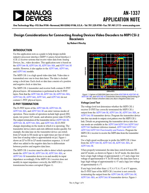
AN-1337APPLICATION NOTE One Technology Way•P.O.Box9106•Norwood,MA02062-9106,U.S.A.•Tel:781.329.4700•Fax:781.461.3113•Design Considerations for Connecting Analog Devices Video Decoders to MIPI CSI-2Receiversby Robert HinchyINTRODUCTIONUse this application note as a guide to help design mobileindustry processor interface (MIPI®) Camera Serial Interface 2(CSI-2) receiver systems that receive video data from AnalogDevices, Inc., video decoders. This application note is based onthe ADV7280-M, ADV7281-M, ADV7281-MA, and ADV7282-Mmodels. However, it also applies to the ADV7480, ADV7481,and ADV7482 models.The MIPI CSI-2 is a high speed video data link. Video data istransmitted over one to four data lanes. The data is clockedusing a clock lane. Each clock or data lane consists of a positiveand negative clock or data line.The MIPI CSI-2 transmitter and receiver both contain D-PHYphysical layers. All termination is performed in the D-PHY layers. Note that the ADV7280-M, ADV7281-M, ADV7281-MA, ADV7282-M, ADV7480, ADV7481, and ADV7482 do not contain C-PHY physical layers.D-PHY TERMINATIONThe D-PHY layers of the ADV7280-M, ADV7281-M,ADV7281-MA, and ADV7282-M can enter various modes of operation. These modes of operation include high speed (HS) mode, low power (LP) mode, and ultralow power state (ULPS). The output termination of the transmitter device (ADV7280-M, ADV7281-M, ADV7281-MA, and ADV7282-M) D-PHY changes depending on the mode in which it is operating. The transmitter device enters and exits different modes quickly. For example, the data lane on the transmitter device can switch from LP mode to HS mode up to eight times per line of video (one line of analog video is approximately 64 μs). Figure 1 shows an LP to HS to LP mode transition sequence. A 50 mV offset was added to the negative data line to differentiate between positive and negative data lines.The MIPI CSI-2 receiver must be able to detect which operation mode the ADV7280-M, ADV7281-M, ADV7281-MA, or ADV7282-M transmitter device is in and modify its input impedance accordingly. If the MIPI CSI-2 receiver does not modify its input impedance correctly, the MIPI CSI-2 transmission becomes corrupted (Figure 3).12775-1(125mV/DIV)Figure 1. Capture of D0P/D0N Data Lines of the ADV7280-M, ADV7281-M, ADV7281-MA, and ADV7282-M Transmitter Devices Exiting and Entering LP Mode (Yellow is Positive Data Line; Blue is Negative Data Line) Voltage Level TestThe voltage level test determines whether the MIPI CSI-2 receiver D-PHY has correctly terminated the MIPI CSI-2 output from the ADV7280-M, ADV7281-M, ADV7281-MA, or ADV7282-M transmitter device. Program the transmitter device into free run mode to output a test pattern over the MIPI CSI-2 link. Details on programming the transmitter device into free run mode are available in the ADV7280/ADV7281/ADV7282/ ADV7283 hardware reference manual, ADV7280/ADV7281/ ADV7282/ADV7283Functionality and Features. Program the MIPI CSI-2 receiver to receive the MIPI data from the transmitter device.Use a high speed oscilloscope to probe the MIPI CSI-2 lines from the ADV7280-M, ADV7281-M, ADV7281-MA, orADV7282-M.When properly terminated, the data lines switch between HS and LP modes, as shown in Figure 2. In LP mode, the data lines have a logic high voltage of approximately 1.2 V and a logic low voltage of approximately 0 V. In HS mode, the data lines have a logic high voltage of approximately 0.3 V and a logic low voltage of approximately 0.1 V.If any logic level other than 1.2 V, 0.3 V, 0.1 V, or 0 V appears, the D-PHY layer of the MIPI CSI-2 receiver is not correctly terminating the output from the ADV7280-M, ADV7281-M, ADV7281-MA, or ADV7282-M transmitter device. Figure 3AN-1337Application Noteshows an example of the MIPI CSI-2 positive data line output from the transmitter device for a poorly terminated receiver. When the transmitter device (ADV7280-M , ADV7281-M ,ADV7281-MA , or ADV7282-M ) is programmed, the MIPI CSI-2 clock lane exits LP mode and enters HS mode. Unless the transmitter device is manually programmed to enter LP mode or is reset, the clock lane remains in HS mode. If any logic level other than 0.3 V or 0.1 V appears on the MIPI CSI-2 clock lines, the D-PHY layer of the MIPI CSI-2 receiver does not correctly terminate the output from the transmitter device.Capture of Positive Data Line in High Speed and Low Power ModesFigure 2 and Figure 3 show the difference between a correct and an incorrect termination of the MIPI CSI-2 signal by the D-PHY layer in the MIPI CSI-2 receiver.12775-002(200m V /D I V )Figure 2. Positive Data Line (D0P) Output from the ADV7280-M , ADV7281-M , ADV7281-MA , and ADV7282-M Transmitter Devices; Correct MIPI CSI-2Receiver Termination12775-003(200m V /D I V )Figure 3. Positive Data Line (D0P) Output from the ADV7280-M , ADV7281-M , ADV7281-MA , and ADV7282-M Transmitter Devices; Incorrect MIPI CSI-2Receiver TerminationD-PHY Mode Detection TestTo test that the MIPI CSI-2 receiver can detect each operation mode, manually program the ADV7280-M , ADV7281-M , ADV7281-MA , or ADV7282-M transmitter device to enter HS mode, LP mode, and ULPS. Then, test the MIPI CSI-2 receiverto verify that it can correctly detect the operation mode of the transmitter device.Refer to the ADV7280/ADV7281/ADV7282/ADV7283hardware reference manual, ADV7280/ADV7281/ADV7282/ ADV7283 Functionality and Features , for details on manually programming the ADV7280-M , ADV7281-M , ADV7281-MA , or ADV7282-M to enter HS mode, LP mode, and ULPS.Clock Lane Low Power to High Speed Transition Some MIPI CSI-2 receivers wait for an LP to HS modetransition on the MIPI CSI-2 clock lane before starting video capture. However, the LP to HS mode transition on the MIPI CSI-2 clock lane occurs only once on the ADV7280-M , ADV7281-M , ADV7281-MA , and ADV7282-M immediately after they are initially programmed.If the MIPI CSI-2 receiver is initialized after the transmitter device is initialized, the MIPI CSI-2 may never detect the LP to HS mode transition on the clock lane from the transmitter device. If the MIPI CSI-2 receiver does not detect the LP to HS mode transition, it may never start video capture.To overcome this issue, manually program the clock lane of the ADV7280-M , ADV7281-M , ADV7281-MA , or ADV7282-M to enter and then exit LP mode. The easiest way to do this is by toggling the CSITX_PWRDN bit (Address 0x00, Bit 7).The MIPI CSI-2 receiver then recognizes an LP to HS mode transition and begins video capture.DESIGN OF MIPI CSI-2 RECEIVER SYSTEMThe following sections provide tips on debugging issues with the MIPI CSI-2 receiver system that is receiving video data from the ADV7280-M , ADV7281-M , ADV7281-MA , or ADV7282-M .Lock StatusWhen an analog video source is connected to the ADV7280-M , ADV7281-M , ADV7281-MA , or ADV7282-M video decoder, it can take the video decoder a period of time before it locks to the incoming analog video. This period of time can take up to 250 ms in fast switch mode and more than 500 ms in autodetect mode. The ADV7280-M , ADV7281-M , ADV7281-MA , or ADV7282-M outputs spurious data over the MIPI CSI-2 link until the device locks to the incoming analog video. It is recommended that the MIPI CSI-2 receiver system be set to ignore the output from the ADV7280-M , ADV7281-M , ADV7281-MA , or ADV7282-M until the ADV7280-M ,ADV7281-M , ADV7281-MA , or ADV7282-M has locked to the analog video.The FSC_LOCK, LOST_LOCK, and IN_LOCK bits (Register 0x10, Bits[2:0]) indicate whether the ADV7280-M , ADV7281-M , ADV7281-MA , or ADV7282-M transmitter device has locked to the analog video source.Use the INTRQ hardware interrupt pin in conjunction with the FSC_LOCK, LOST_LOCK, and IN_LOCK bits to verify when a lock event has occurred. Using the INTRQ hardware interruptApplication Note AN-1337pin saves the MIPI CSI-2 receiver from constantly polling the FSC_LOCK, LOST_LOCK, and IN_LOCK bits.Use the CSITX_PWRDN bit to stop the MIPI CSI-2 output from the ADV7280-M, ADV7281-M, ADV7281-MA, orADV7282-M. Stop the MIPI CSI-2 output until the ADV7280-M, ADV7281-M, ADV7281-MA, or ADV7282-M has locked to the analog video source, as indicated by the INTRQ hardware interrupt pin.For more information on the CSITX_PWRDN, FSC_LOCK, LOST_LOCK, and IN_LOCK bits and on the INTRQ hardware interrupt pin, see the ADV7280/ADV7281/ADV7282/ADV7283 hardware reference manual, ADV7280/ADV7281/ ADV7282/ADV7283Functionality and Features. DeinterlacerBy default, the ADV7280-M, ADV7281-M, ADV7281-MA, and ADV7282-M transmitter devices output video data in an interlaced format in the YCbCr 4:2:2 color space. In most applications, the MIPI CSI-2 receiver system requires a deinterlacing function. The most common way of performing this function is by using a frame buffer. For example, an odd field and an even field of video are transmitted into a memory buffer in the MIPI CSI-2 receiver system. The data stored in the memory buffer is then analyzed as a complete progressive frame of video by the MIPI CSI-2 receiver system.Alternatively, the ADV7280-M and ADV7282-M transmitter devices have an integrated deinterlacer. This is referred to as the interlaced to progressive (I2P) core in the ADV7280-M and ADV7282-M data sheets and in the hardware reference manual, ADV7280/ADV7281/ADV7282/ADV7283Functionality andFeatures. Using the I2P cores on the ADV7280-M and the ADV7282-M transmitter devices and programming them to output in progressive mode eliminates the need for deinterlacing in the MIPI CSI-2 receiver system.The I2P core of the ADV7280-M and ADV7282-M interpolates between two lines of video. An algorithm is used to smooth the resulting image to minimize low angle artifacts.Odd and Even Fields of Different LengthsThe ADV7280-M, ADV7281-M, ADV7281-MA, andADV7282-M video decoders output video over the MIPI CSI-2 stream. However, the video timing is based on the ITU-R BT.656-3 or ITU-R BT.656-4 standard.In interlaced mode, an NTSC video source results in theADV7280-M, ADV7281-M, ADV7281-MA, and ADV7282-M transmitter devices outputting video where the odd fields are one line longer than the even fields. This difference occurs with NTSC sources only. PAL sources result in even and odd fields of the same length.When designing video frame buffers in the MIPI CSI-2 receiver system, the even and odd fields can be of different length. However, the ADV7280-M and ADV7282-M models with I2P cores can be programmed to output progressive video. In progressive mode, all fields output by the transmitter devices are the same length.For more information on the video output timing or the I2P core, see the ADV7280/ADV7281/ADV7282/ADV7283 hardware reference manual, ADV7280/ADV7281/ADV7282/ ADV7283Functionality and Features.Video Frame Buffer OverflowsMost MIPI CSI-2 receivers contain a video frame buffer. Each video frame from the ADV7280-M, ADV7281-M, ADV7281-MA, or ADV7282-M transmitter device is stored in a memory buffer before being analyzed by the MIPI CSI-2 receiver.Under certain circumstances (if the analog video source is disconnected, for example), the ADV7280-M, ADV7281-M, ADV7281-MA, or ADV7282-M transmitter device can output video frames with a nonstandard number of lines because the transmitter device is designed to be effective at processing poor video sources.When the CVBS source is not present, the ADV7280-M,ADV7281-M, ADV7281-MA, or ADV7282-M transmitter device continues to output MIPI CSI-2 video data and enters a search mode. When the device is in search mode, any noise on the CVBS input is tested to determine whether it is an analog video signal. When in search mode, the transmitter device outputs frames that are much longer than standard.The ADV7280-M, ADV7281-M, ADV7281-MA, or ADV7282-M transmitter device remains in search mode for approximately 1 sec in autodetect mode. In fast switch mode, the transmitter device remains in search mode for approximately six fields of video.If a valid analog video source is not detected after the period where the ADV7280-M, ADV7281-M, ADV7281-MA, or ADV7282-M is in search mode, the device determines that no video source is present. The device then exits search mode and enters free run mode. In free run mode, the ADV7280-M, ADV7281-M, ADV7281-MA, or ADV7282-M transmitter device outputs test pattern video frames with standard timing. These nonstandard video frames output during search mode can cause a buffer overflow event in the MIPI CSI-2 receiver. One of the best solutions to prevent a buffer overflow is to use a line counter.The line counter is a control loop in the MIPI CSI-2 receiver that counts the number of lines being output per frame by the ADV7280-M, ADV7281-M, ADV7281-MA, or ADV7282-M transmitter device. If the number of lines output per frame exceeds a limit, the MIPI CSI-2 receiver ignores the output from the transmitter device until the next frame start packet. Choose the line number limit so that the video buffer memory of the MIPI CSI-2 receiver does not overflow and so that standard video sources are not attenuated.AN-1337 Application NoteBy default, the MIPI CSI-2 frame start/end packets and the MIPI line start/end packets are output by the ADV7280-M, ADV7281-M, ADV7281-MA, or ADV7282-M transmitter device.Free Run ModeWhen the ADV7280-M, ADV7281-M, ADV7281-MA, or ADV7282-M transmitter device is programmed into free run mode, the device ignores the analog video input and outputs a fixed test pattern. Free run mode can help customers debug issues with their MIPI CSI-2 receiver systems. A number of test patterns are available. For more information, see the ADV7280/ ADV7281/ADV7282/ADV7283 hardware reference manual, ADV7280/ADV7281/ADV7282/ADV7283Functionality and Features.LAYOUT OF MIPI CSI-2 TRACESMIPI CSI-2 is designed as a chip to chip interface; therefore, it does not transmit over long distances. The D-PHY specification defines the maximum lane flight time to 2 ns. Using standard printed circuit board (PCB) materials and design rules (for example, transmitting MIPI CSI-2 through a microstripline on a standard FR4 PCB), results in a maximum trace length of 25 cm to 30 cm. Therefore, keep the MIPI CSI-2 traces from the ADV7280-M, ADV7281-M, ADV7281-MA, or ADV7282-M transmitter device to the MIPI CSI-2 receiver under 30 cm in length.MIPI CSI-2 line traces must have a characteristic impedance of 50 Ω single-ended and 100 Ω differential.Loosely couple the positive and negative lines of each lane (for example, Data Line 0 positive; Data Line 0 negative) because the positive and negative lines are differential in HS mode but are single-ended in LP mode. As a general rule, space apart the line traces by a distance equal to twice the thickness of the PCB dielectric.Connect MIPI CSI-2 traces from one ADV7280-M, ADV7281-M, ADV7281-MA, or ADV7282-M transmitter device to one MIPI CSI-2 receiver. It is not possible to daisy-chain multipleADV7280-M, ADV7281-M, ADV7281-MA, or ADV7282-M transmitter devices to one MIPI CSI-2 receiver.All filtering and termination is performed in the D-PHY layer of the ADV7280-M, ADV7281-M, ADV7281-MA, andADV7282-M transmitter devices and in the D-PHY layer of the MIPI CSI-2 receiver. Do not place additional components, such as resistors, electrostatic discharge (ESD) diodes, capacitors, or common-mode chokes on the MIPI CSI-2 traces. REFERENCESMIPI® Alliance Specification for D-PHY, Version 1.00.00, Mobile Industry Processor Industry Alliance, 2009.MIPI® Alliance Specification for Camera Serial Interface 2 (CSI-2), Version 1.01.00, Mobile Industry Processor Industry Alliance, 2010.©2014 Analog Devices, Inc. All rights reserved. Trademarks andregistered trademarks are the property of their respective owners.AN12775-0-12/14(0)。
- 1、下载文档前请自行甄别文档内容的完整性,平台不提供额外的编辑、内容补充、找答案等附加服务。
- 2、"仅部分预览"的文档,不可在线预览部分如存在完整性等问题,可反馈申请退款(可完整预览的文档不适用该条件!)。
- 3、如文档侵犯您的权益,请联系客服反馈,我们会尽快为您处理(人工客服工作时间:9:00-18:30)。
如果您没有使用视讯系统,我们可为您提供由Vidtel提供的低价视讯 解决方案。
使用最新的协作应用程序就像 下载一个应用程序一样简单。 GoToMeeting®、WebEx™、 Microsoft Lync™、Adobe®和 Connect™等采用业界标准的 协作工具可在Mondopad上无 缝运行。
条形音箱
电源
60 Hz AC
扬声器驱动器(左右声道) 两个3英寸和一个3/4英寸钕磁铝带式高音喇叭(每侧)
功率输出(RMS)
25瓦/声道 @ 1% THD、1KHz、2声道驱动、70瓦(整个系统峰值)
频率响应
90Hz-20KHz
系统
包含配件
保修期 发货重量 发货尺寸
工作条件 噪声 能源之星 认证
无线键盘(如需要),无线鼠标(如需要),清洁布,VGA线,USB线,固定螺钉,固定螺钉装卸工具,电源线, 遥控器,快速设置指南,条形音箱装配件,HD摄像头装配件,脚架装配件 1年 显示器、PC和摄像头:136磅/61.70千克;条形音箱:14.33磅/6.5千克;支架:9.26磅/4.2千克 显示器、PC和摄像头:58.66 x 13.86 x 38.39英寸/149 x 35.2 x 97.50厘米; 条形音箱:57.48 x 7.08 x 5.7英寸/143 x 18 x 14.5厘米;支架:22.05 x 5.31 x 15.94英寸/56 x 13.5 x 40.5厘米 5°-35°C(0-10K ft) <40dBA @ 25°C 5.1(显示器和PC) 美国、加拿大、欧盟、澳大利亚、新西兰和中国
PDF、JPG等)——所有文档格式都经过优化适合触摸屏显示。
决不错过任何一个观点
使用白板中的书写和制图工具为屏幕上演示的任何内容添加注释。高度 视觉化的媒介让您的团队更加高效地沟通,实时地协作,决不错过任何 一个观点。 对PPT幻灯片、电子表格、设计图
(design comp)等上面的重要信 息可加圆圈或高亮显示。 标识屏幕上的信息,帮助远程与会 者跟上会议进度。 获取观点并通过Mondopad与所有 与会者分享。
型号
INF5520
可选配件
墙壁安装件(INF-WALLMNT2) 移动推车(INF-MOBCART) 地面安装支架(INF-FLRSTND) 配件架(INF-ACCYSHELF) 网络摄像头支架(INF-VIDSHELF) 气动调节高度辅助设备(INF-STND-LIFT) 延长的保修期
53 英寸 1346 毫米
*产品规格、术语和各类产品可能会随时改变,恕不另行通知。
©2011 富可视公司。保留所有权利。产品规格可能会随时改变,恕不另行通知。InFocus、InFocus Bright Ideas Made Brilliant和Mondopad是富可视公司在美国和其它国家/地区使用的商标或注册商标。
所有商标的使用均已获得许可,并只用于识别目的。使用的所有商标属于其各自所有公司的财产。 InFocus_Mondopad_DS_4Page_CN_21OCT11
您的会议室需要Mondopad的理由
多触摸屏高清晰度55英寸显示器 高性能Intel® i5 PC运行Windows 7 Pro 完全复制Microsoft® Office 数字白板 高分辨率720p摄像头,带4个一体化麦克风 最佳语音条形音箱,提高会话清晰度
专为多触摸屏而设计
PC
处理器 内存 硬盘 LAN (2x) Wi-Fi 输入连接 操作系统 内置软件
Intel(R) Core i5-2520m、QM67芯片组,支持AMT 7.1 4 GB、8 MB闪存 SATAII 320 GB 5400 RPM 802.3 10/100/1000 Base-T with Wake on LAN 双频段802.11 a/b/g/n MIMO PCIe半迷你卡、2.4 GHz,支持Intel、AMT USB 2.0类型A x 2 Windows 7 Pro 64位 Microsoft Office家庭版和企业版32位、Mondopad接口软件
38.3 英寸 973 毫米
5.5 英寸 140 毫米
Mondopad 遥控器
|
富可视公司总部 13190 SW 68th Parkway Portland, Oregon 97223-8368, USA 电话: (+1) 503-207-4700 免费长途电话: (+1) 877-388-8385 传真: (+1) 503-207-1937
Mondopad自然流畅的触摸屏界面改变了人们与信息交互、协作和连接 的方式。有了它,会议将变得精彩纷呈,内容更具沉浸感,听众更加专 注投入。
内置的MondoControl软件充分利用了Mondopad多触摸屏功能,简化并 优化了其所有的演示、注释和协作应统,Mondopad最适合您。您可以把它作为一个 SIP端点加入到您的视讯服务器或服务上。您也可以在Mondopad上安 装桌面客户端,用于您现有的视讯系统,如同PC一样。
55英寸
全高清 1080p (1920 x 1080)
白板向导
Mondopad的白板和协作应用程序让您轻松地组织头脑风暴会议并获取 和分享观点。
一组完整的书写和制图工具、笔、 荧光笔、形状和线条,供您自由 选用。
您可采集、保存会议视图中的白 板图形和注释,并通过Mondopad 以电子邮件形式将其发送给各与 会者。
熟悉的应用程序,针对触摸屏优化
通过Mondopad简单且熟悉的文件夹结构可在会议中轻松地分享来自任 何设备的文档和视图。 通过所有与会者都可以访问的Mondopad的View/Share(“视图/分
享”)文件夹可添加、删除和发布文档。 您也可以直接通过电子邮件把文件发送到Mondopad。 还可使用您日常使用的所有办公文档(PowerPoint、Word、Excel、
摄像头
分辨率 帧率 镜头及视野 音频支持 接口 聚焦 云台 电源
1280 x 720 22fps at HD with H.264+YUV(双向) F/2.0、3P镜头;FOV(D) 56.8°(HD模式)、FOV(D) 50°(VGA模式)1.0x缩放、FOV(D) 30°(VGA模式)1.6x缩放 4个内置单向麦克风 USB 2.0高速 自动对焦 手动上/下和左/右±40° 通过USB供电
升级您的会议室
Mondopad通过具有成本效益的优雅包装把多功能一体化PC的强大功能
和灵活性与大触摸屏显示器整合在一起。此外,它还可以通过扩展满足
您的诸多需求。Mondopad采用业界 标准和来自Intel和Microsoft的领先技
术,因此可轻而易举地升级到最新 的软件和工具。IT管理者和托管服务 提供商可在任何地方以安全的方式 对Mondopad进行监视和管理。
Mondopad的宗旨是使商务会议告别 枯燥乏味。
CNET Crave
规格*
显示器
大小 分辨率 刷新频率 视角 显示器色彩 像素间距 画中画 视频输入兼容性 数据输入兼容性
输入
输出 触摸屏
扬声器(一体化) 电源 安装件
55英寸 1920 x 1080 60 Hz ±89° 1.07G(10-位) 0.63毫米 SBS/4象限PiP 完全兼容NTSC、480i、480p、720p、1080i、1080p/24、1080p/30、1080p/60 VGA (640x480)、SVGA (800x600)、XGA (1024x768)、SXGA (1280x1024)、SXGA+ (1400x1050)、UXGA (1600x1200)、WXGA+ (1440x900)、WSXGA+ (1680x1050)、WXGA (1280x800)、WUXGA (1920x1200) USB类型-A x 6、HDMI 1.3 x 2、VGA (HD15 VESA)、分量、S-Video、复合、RS232、RCA立体声 x 2、 3.5毫米立体声迷你插孔、连接至触摸屏控制板的USB B、Ethernet (RJ45 x 2) RCA音频立体声(L/R)输出至条形音箱或其它外置A/V系统 多触摸屏系统,支持2个触摸屏和Windows 7操作系统 LCD表面带玻璃保护膜 通过USB连接触摸屏系统面板到PC 立体声7W x 2 AC 100-240V、50/60Hz VESA标准400 x 400毫米M6螺钉
连接、分享、查看和控制来自任何设备的内容
您和您的同事可在任何地方以安全的方式接入会议、分享观点并开展协 作——这使得会议更具协作性、更富有成效且更具可持续性。 通过Mondopad内置的WiFi功能安全地将其接入您的网络,使网络中
的所有授权用户均可通过他们的PC、平板电脑或智能手机分享、查 看和控制他们的视图。 Mondopad内置的WiFi功能还可建立一个无线接入点,使会议室中的 贵宾能够轻松地把文档传递到显示屏,或无需通过连接公司的专用网 络就可接入因特网。 远程与会者可通过Mondopad提供的网页查看Mondopad上面的内容。
大触摸屏平板电脑,会议室的理想 选择
通过一个大屏幕平板电脑与会议室及全世界的与会者一起演示、 注释和协作。
InFocus Mondopad™可为您形象地演示您所需要的一切,只需 动一下指尖就可以获取和分享观点——所有的一切都完美集成于 一台单独的设备上。
Mondopad通过具有成本效益的优雅包装把多功能一体化PC的 强大功能和灵活性与大触摸屏显示器整合在一起。Mondopad 基于业界标准和领先技术设计制造。