CTDO3316P-222中文资料
MC34167MC33167中文资料
MC34167 MC331671简介该MC34167, MC33167系列单片电源开关可用于dc–to–dc优化调节器申请.这些器件的固定频率,电压模式稳压器包含了所有的积极作用需要直接和实施step–down以最小的转换数量voltage–inverting外部元件.它们也可以用于成本效益在step–up转换器应用.潜在市场包括汽车,计算机,工业和成本敏感的消费产品.每一个设备的部分介绍给下面与代表框图所示图13.2振荡器振荡器频率内部编程72 kHz的电容CT和修剪电流源.该充放电率控制在产生一个95%在开关输出的最大占空比.在CT的放电,振荡器产生内部消隐脉冲持有的反相输入与门高,禁用输出开关晶体管.标称振荡器峰值和山谷门槛4.1 V和2.3 V分别.3脉宽调制器脉宽调制器由一个比较器振荡器斜坡电压施加到非反相输入端,而误差放大器的输出应用到反相输入.输出开关导通时启动CT检查排放到振荡器峰谷电压.至于收费的CT电压超过误差放大器的输出,锁存复位,终止输出晶体管的导通时间振荡器的ramp–up时期.这PWM /锁存结合防止在给定的多输出脉冲振荡器时钟周期.数字6和14说明开关输出电压与占空比的补偿.4电流检测该系列采用MC34167当前cycle–by–cycle限制,作为保护手段输出开关晶体管从过度紧张.在每个周期视为一个单独的情况.电流限制是通过监测输出开关晶体管的电流传导期间建设,并经检测过流情况,请立即关闭为振荡器的ramp–up期内开关.集电极电流转换为电压由内部微调电阻和对一个参考比较由电流检测比较器.当电流限制达到阈值,比较器重置PWM 锁存.限流门限点往往设在6.5 A.图9说明开关与输出电流限制门槛温度.5误差放大器和参考一个误差放大器的高增益提供了访问反相输入和输出.该放大器具有典型dc电压增益80 dB,和单位增益带宽600 kHz与相边缘 70度(图3).同相输入偏置内部5.05 V参考并且不固定了.参考具有精度±2.0%在室温下.以提供负载5.0 V中,参考编程50以上mV 5.0 V补偿在电缆的电压降和1.0%从连接器转换器输出.如果转换器设计需要一个输出电压高于5.05 V,电阻更大R1必须加入形成一个分压网络的反馈输入中所示数字13和18.了确定输出方程与分压网络的电压为:Vout+5.05R2R1)1外部回路补偿所需的转换器稳定.一个简单的low–pass滤波器是由连接电阻(R2)从稳压输出到反相输入,以及一系列resistor–capacitor (RF, CF)之间Pins 1和5.补偿网络的元件值显示在电路的申请被选定为each在稳定工作条件下进行测试.该step–down转换器(图18)是最容易补偿稳定.该step–up(图20)和voltage–inverting(图22)配置运作,连续导反激式转换器,而且更难以弥补.该最简单的方法来优化网络是补偿观察输出电压的负载响应一步变化,而调整临界阻尼RF和CF.该最终电路应验证以下四个稳定边界条件.这些条件是最小和最大输入电压,最小和最大负载.通过箝位的电压误差放大器的输出(引脚5)不到150 mV,内部电路将放置到一个低功耗待机模式,从而将权力电源电流36µA与12 V电源电压.图10说明了备用电源电流与电源电压.误差放大器的输出有一个100µA电流源pull–up,可用于实现soft–start.图17显示充电电流源通过一个电容CSS系列二极管.该二极管断开从反馈CSS回路电阻时1.0 M操作它上面的收费销5.范围开关输出输出开关晶体管的设计最大的40 V,以最小的峰值集电极电流时5.5 A.配置为step–down或voltage–inverting应用,如在图18和22,电感会把偏置的输出整流开关关闭时.整流器与较高的正向电压降或长期拖延的时间应该打开不能使用.如果发射器被允许去充分负,集电极电流流过,造成额外的装置暖气,降低转换效率.图8显示到箝位的发射器0.5集电极电流V,在一系列的100µA温度过高.阿1N5825或肖特基势垒整流器相当于推荐履行这些要求.欠压分离欠压分离一直比较成立以保证完全集成电路在输出级的功能已启用.内部参考电压比较器的监测使输出阶段VCC超过5.9 V.为了防止不稳定的输出交叉切换的阈值,0.9 V迟滞.6摩托罗拉设备数据模拟ICMC34167 MC33167热保护内部热关断电路,以保护在事件集成电路的最大结温度超过.当被激活时,通常在170°C,是被迫的锁存成'复位'的状态,关闭输出开关.此功能防止灾难性故障提供偶然的设备过热.它的目的不是要作为一个适当的散热片的替代品.该MC34167包含在5–lead TO–220类型包装.该标签包装是很常见的中心引脚(引脚3),通常连接到地.设计考虑不要试图建立一个转换器上wire–wrap或plug–in原型板.特别应注意分开的信号电流和接地接地通路从负载电流路径.所有高电流回路应尽可能短尽可能使用重型铜runs到尽量减少振荡和辐射EMI.为了获得最佳的操作,严密元件布局建议.电容器Cin, CO,和所有的反馈元件应尽可能靠近IC在身体可能.这也是必须的肖特基二极管连接到开关输出是尽可能靠近尽可能IC.图15.低功耗待机电路+100µA错误放大器1图16.过电压关断电路+100µA错误放大器1120补偿5120补偿R15R1I =待机模式VShutdown = VZener + 0.7图17. Soft–Start电路+100µA错误放大器1120补偿D2Vin1.0 MCss5D1R1tSoft–Start≈35,000 Css。
维特根全系列发动机滤芯

发动机型号: W200 Milling Machine 配康明斯 QSX15 发动机
维特根 / 型号:W2000
发动机型号: W2000 Milling Machine 配Cat 3406 发动机 维特根 / 型号:W200i
发动机型号: W220 Milling Machine 配Cat C18 发动机 维特根 / 型号:W2200
发动机型号: W2200 Milling Machine 配Cat 3412E 发动机 维特根 / 型号:W250
发动机型号: W250 Milling Machine 配康明斯 QSX15 QSL8.9 Engs. 维特根 / 型号:W250
发动机型号: W35DC Cold Millling Machine 配道依茨D2011 L04 发动机 维特根 / 型号:W50
发动机型号: W50 Milling Machine (08.05 系列) 配道依茨BF4M2011 发动机 维特根 / 型号:W50
发动机型号: W50 Milling Machine (10.05) 配道依茨BF4M2011 发动机 维特根 / 型号:W500
发动机型号: WM1000 Slurry Mixer 配道依茨BF6M1013 发动机
维特根 / 型号:WR200
发动机型号: WR200 Recycler 配梅赛德斯奔驰 OM460LA 发动机 维特根 / 型号:WR2000
发动机型号: WR2000 Recycler 配梅赛德斯奔驰 OM502LA 发动机 维特根 / 型号:WR2000
发动机型号: W100F W120F W130F Milling Machines 配康明斯 QSC8.3 发动机
CAT-316-DA 3 16 PRO. 6 随机轨道掌型沙子说明书
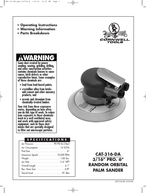
This Instruction Manual Contains Important Safety Information.Read THIS INSTRUCTIONMANUAL Carefully andunderstand ALL INFORMATIONBefore Operating THIS Tool.• Always operate, inspect and maintain this tool in accordance withAmerican National Standards InstituteSafety Code of Portable Air Tools (ANSIB186.1) and any other applicable safetycodes and regulations.•For safety, top performance and maximum durability of parts, operate this tool at 90psig 6.2 bar max air pressure with 3/8"diameter air supply hose.• Always wear impact-resistanteye and face protection whenoperating or performingmaintenance on this tool.Always wear hearing protectionwhen using this tool.• High sound levels can causepermanent hearing loss. Usehearing protection asrecommended by your employeror OSHA regulation.•Keep the tool in efficient operatingcondition.•Operators and maintenance personnel must be physically able to handle the bulk, weight and power of this tool.• Air under pressure can causesevere injury. Never direct air atyourself or others. Always turnoff the air supply, drain hose ofair pressure and detach toolfrom air supply before installing, removing or adjusting any accessory onthis tool, or before performing anymaintenance on this tool. Failure to do socould result in injury. Whip hoses cancause serious injury. Always check fordamaged, frayed or loose hoses andfittings, and replace immediately. Do notuse quick detach couplings at tool. Seeinstructions for correct set-up.• Air powered tools can vibratein use. Vibration, repetitivemotions or uncomfortablepositions over extended periodsof time may be harmful to yourhands and arms. Discontinue use of tool if discomfort, tingling feeling or pain occurs. Seek medical advice beforeresuming use.•Place the tool on the work before starting the tool.• Slipping, tripping and/or fallingwhile operating air tools can bea major cause of serious injury ordeath. Be aware of excess hoseleft on the walking or worksurface.•Keep body working stance balanced and firm. Do not overreach when operating the tool.•Anticipate and be alert for sudden changes in motion during start up and operation ofany power tool.• Do not carry tool by the hose.Protect the hose from sharpobjects and heat.•Do not lubricate tools with flammable or volatile liquids such as kerosene, diesel or jet fuel.•Don't force tool beyond its rated capacity.•Do not remove any labels. Replace any damaged labels.WARNING!FAILURE TO OBSERVE THESE WARNINGS COULD RESULT IN INJURY CAT-316-DA_man-010704.q 1/8/04 12:36 PM Page 210111213141515A 1617111111111111111511Qty.11113111111111112(Optional)Qty.Ref. #RS31601RS47502RS47503RS47504RS47505RS47506RS47507RS47508RS31609RS47510RS10920RS47512RS47513RS47514RS47515RS47515A RS47516RS47517Description Lever Pin Muffler Muffler Body Inlet Bushing Spring Valve Seat Housing Ring Bearing Rear End Plate Cylinder Assy.O-Ring Rotor Rotor Blade Ring Control Description O-Ring Stem Key Front End Plate Bearing O-Ring Lock Ring Shaft Balancer--3/16" Orbit Shim Washer Ring Spindle 6" TE NV Vinyl Face Pad Pad Wrench O-Ring Plate Screw Vacuum Conversion Kit 6" TE NV Hook Face Pad6" TE Vacuum Hook Face PadPart #Ref. #Part #RS47518RS47519RS47520RS47521RS227B25RS47523RS47524RS47525RS47527RS47529RS47530RS47531CAT-6NV-PAD RS47533RS47534RS47535RS47536CAT-4126CAT-6NVH-PAD CAT-6VH-PAD 1819202122232425272930313233343536Also available:。
zc一kpp2一22控制电缆护套参考书上执行标准

zc一kpp2一22控制电缆护套参考书上执行标准ZCJL-C3-20A型电缆护套分为三层结构,外包三层绝缘护套外包两层聚乙烯绝缘护套外包三层聚氯乙烯绝缘护套外包四层聚氯乙烯绝缘护套外包两层聚氯乙烯绝缘护套外包三层聚乙烯绝缘护套外包两层聚氯乙烯绝缘护套外包三层聚氯乙烯绝缘护套外包三层聚氯乙烯绝缘护套外包三层聚氯乙烯绝缘护套外包三层聚氯乙烯绝缘护套外包三层聚氯乙烯绝缘护套外包三层聚氯乙烯绝缘护套外包三层聚氯乙烯绝缘护套外包三层聚氯乙烯绝缘护套外包三层聚乙烯护套内包三层聚氯乙烯绝缘护套外包四层聚乙烯护套外保护内包聚乙烯绝缘护罩外面包裹三层聚氯乙烯护套外包三层聚乙烯绝缘护套内包尼龙护套外包聚乙烯护套外包百层氟塑护套外包百里型电缆保护套管。
该型电缆保护套保护线一、适用于各种电力电缆,仪表电缆,控制电缆的安装保护。
本产品可满足电力电缆和电气控制电缆绝缘、护套及绝缘线的安装保护的要求。
本产品有多种规格可供选择,可根据客户需求定做。
产品的用途:本产品可用于各种电力电缆、电气控制电缆、工矿光缆、信号电缆、通信电缆等各种规格电缆保护设备。
适用于各种电压等级、电力电缆敷设在地下,以保证电力设备及其附属设施安全运行和正常工作状态下的电力电缆能够进行绝缘防护的设备和装置;适用于控制电缆敷设在地下,因其本身就具有一定的自洁功能;可根据要求选用相应厚度(0.6-3.0 mm)或不同直径(2-4 mm)的保护套可根据用户要求选用)。
1、安装工艺a.将本产品放入配电箱。
b.用机械方法将外护套固定(一次固定、五次固定)。
c.再将电缆护套固定于配电箱地面上。
e.将绝缘层剥去不能承受重量的部分)、做好记号后即告完成安装工作;本产品由护套主体和外护套两部分组成。
2、护套材料要求护套材料采用高强度橡胶。
橡胶厚度为0.2 mm,按 GB/T3154-1998规定应符合表3的规定,允许选用不大于0.3 mm厚度的橡胶。
橡胶应具有一定的弹性、耐磨性、耐老化性和耐化学稳定性。
MC33161PG资料

Recommended Operating Conditions is not implied. Extended exposure to stresses above the Recommended Operating Conditions may affect
device reliability.
2. Maximum package power dissipation must be observed.
3. Tlow = 0°C for MC34161 −40°C for MC33161
Thigh = +70°C for MC34161 +105°C for MC33161
−40°C for NCV33161
Operating Junction Temperature
Operating Ambient Temperature (Note 3) MC34161 MC33161 NCV33161
VCC Vin ISink Vout
PD RqJA PD RqJA RqJA
TJ TA
40
V
− 1.0 to +40
元器件交易网
MC34161, MC33161, NCV33161
Universal Voltage Monitors
The MC34161/MC33161 are universal voltage monitors intended for use in a wide variety of voltage sensing applications. These devices offer the circuit designer an economical solution for positive and negative voltage detection. The circuit consists of two comparator channels each with hysteresis, a unique Mode Select Input for channel programming, a pinned out 2.54 V reference, and two open collector outputs capable of sinking in excess of 10 mA. Each comparator channel can be configured as either inverting or noninverting by the Mode Select Input. This allows over, under, and window detection of positive and negative voltages. The minimum supply voltage needed for these devices to be fully functional is 2.0 V for positive voltage sensing and 4.0 V for negative voltage sensing.
P331-2带ESD发生器(IEC 61000-4-2)用户手册说明书

User manualP331-2 setESD generator(IEC 61000-4-2)Copyright © January 2017LANGER EMV-Technik GmbHTable of Contents Page1Declaration of Conformity (3)2General Information (4)2.1Storage of the User Manual (4)2.2Reading and Understanding the User Manual (4)2.3Local Safety and Accident Prevention Regulations (4)2.4Images (4)2.5Limitation of Liability (4)2.6Errors and Omissions (4)2.7Copyright (4)3Scope of delivery (5)4Technical Parameters (6)4.1P331-2 ESD generator (6)4.2BPS 203 Burst Power Station (6)4.3SM 02-01 Shunt (7)5Safety (8)5.1Labels and Signs (8)5.2Intended Use (8)5.3Reasonably foreseeable Misuse (8)5.4Staff Requisition (9)5.5Safety Instructions (9)6P331-2 ESD Generator (IEC 61000-4-2) (10)6.1Design and Function of the P331-2 probe (10)6.2Characteristics (11)7Operational Notes (12)8System Set-Up (13)9Verifying the Waveform (15)10Warranty (16)1 Declaration of ConformityManufacturer:Langer EMV-Technik GmbHNöthnitzer Hang 3101728 BannewitzGermanyLanger EMV-Technik GmbH herewith declares that theP331-2 set, ESD generatorwith P331-2, BPS 203conforms with the following relevant regulations:-EMC Directive 2014/30/EU-Low-Voltage Directive 2014/35/EU-Restriction of certain Hazardous Substances 2011/65/EUThe following applicable standards were used to implement the requirements specified by the aforementioned directives:-EN 61000-6-1:2007-10 (EMC)-EN 61000-6-3:2011-09 (EMC)-EN 61010-1:2011-07 (Safety)-DIN EN 50581:2013-02 (Restriction of hazardous substances)Name of the person authorized to compile the technical file:Gunter LangerBannewitz, 2020-03-02Signature:_________________G. Langer, Managing Director2 General Information2.1 Storage of the User ManualThis user manual enables the safe and efficient use of the P331-2 set. It must be kept close at hand and accessible to the user.2.2 Reading and Understanding the User ManualRead the user manual carefully, observe the safety information (Chapter 5) and follow the instructions given in this manual before putting the device into service.2.3 Local Safety and Accident Prevention RegulationsThe local accident prevention and general safety regulations also apply to ensure that the P331-2 set is used for its intended purpose.2.4 ImagesFigures have been included in this user manual to assist the reader's understanding but may differ from the device's actual version.2.5 Limitation of LiabilityIn the following cases, Langer EMV-Technik GmbH can assume no liability for damage to property and personal injury if:- The information given in this user manual has not been observed.- P331-2 set was operated by staff not qualified in the field of EMC.- P331-2 set was subjected to unauthorized modifications or technical changes.- P331-2 set was not used according to its intended purpose.- Spare parts or accessories were used that had not been approved byLanger EMV-Technik GmbH.The actual scope of delivery may deviate from the illustrations and texts in this user manual due to the customization of orders or due to technical changes and innovations.2.6 Errors and OmissionsThe information in this manual has been carefully checked and is believed to be accurate; however, the Langer EMV-Technik GmbH assumes no responsibility for any clerical, typographical, or proofreading errors, or omissions.2.7 CopyrightThe content of this user manual is protected by copyright law and may only be used in connection with the P331-2 set. This user manual may not be used for any other purpose without the prior written approval of Langer EMV-Technik GmbH.3 Scope of deliveryItem Designation Type Parameter Pcs.01 ESD Generator (probe) P331-2 102 Burst Power Station BPS 203 103 Control software BPS 203-Client 104 Shunt SM 02-010.1 R 105 Control cable FBK 12P 1 m 106 High-voltage cable HV FI-FI 1 m 107 USB cable type A-B USB-AB 108 Measuring cable SMA-SMB 1 m 109 Power supply unit 12 V / 1 A 110 System case P331 case 111 User manual 112 Quick guide 1 Important: The scope of delivery may deviate depending on the respective order.4 Technical Parameters 4.1 P331-2 ESD generator4.2 BPS 203 Burst Power Station4.3 SM 02-01 Shunt5 Safety5.1 Labels and SignsGeneral warning sign Warning; Electricity Prohibition sign; No access for people with active implantedcardiac devices.Table 5: Safety signsSafety instructions in this user manual are marked by symbols (Table 5). Observe the safety precautions and act cautiously to avoid accidents as well as personal and material damages.5.2 Intended UseThe P331-2 set is used for conducted coupling of ESD pulses into ICs. The P331-2 probe sizing orientates itself by mechanisms of the ESD coupling into electronic assemblies (according to IEC 61000-4-2 / HMM1). The BPS 203 burst power station supplies and controls the probe.The P331-2 probe and BPS 203 burst power station are built according to their specified use therefore they should be used only for the following purposes:- Injection of ESD pulses into IC pins or balls with P331-2 powered by BPS 203.- Control of the P331-2 via BPS 203-Client or DLL.- The P331-2 set must be used in conjunction with the ICE1 set from Langer EMV-Technik GmbH. Any use beyond these specifications is considered contrary to the intended use.5.3 Reasonably foreseeable MisuseDanger resulting from misuse!Misuse of the P331-2 set can lead to dangerous situations!-Use of the product outside of the given specifications.-Modification or changing of the product without consent of Langer EMV-Technik GmbH.-Operating the product with a technical fault.1 HMM – Human Metal ModelWarning!5.4 Staff RequisitionOnly qualified staff with training, knowledge, and experience in the field of EMC is allowed to operate the P331-2 set.Persons whose ability to perform is influenced or impaired by alcohol, drugs, or pharmaceuticals, are not allowed to operate the P331-2 set.Certain functions may only be carried out by qualified personnel of Langer EMV-Technik GmbH. 5.5 Safety InstructionsDanger resulting from Electricity!Risk of injury by electrocution!Warning; ElectricityOnly connect the high-voltage cable to the P331-2 probe before operation.Don’t touch the probe tip of a P331-2 probe while it is in operation.-If insulation is damaged, the power supply has to be disconnected immediately.- Replace damaged parts with undamaged parts before operation. Contact Langer EMV-Technik GmbH for proper replacements.-Protect live parts from moisture to avoid short circuits.Never leave a Langer EMV-Technik GmbH product unattended while this is in operation.Danger resulting from electromagnetic fields!Risk of affecting a cardiac device!Prohibition; Noaccess for peoplewith active implantedcardiac devicesPersons with a cardiac device, such as a pacemaker, are not allowed to work on or approach the P331-2 set while it is in operation.6 P331-2 ESD Generator (IEC 61000-4-2)The probe is used to generate standard ESD pulses according to IEC 61000-4-2 for ESD injection into the device under test via conductors (Figure 2: P331-2 pulse form).The P331-2 probe allows the user to couple ESD into IC pins via conductors according to the standard IEC 61000-4-2 both directly and indirectly via coupling networks (standard). Coupling networks are used for coupling into interface connections or special high-speed interfaces such as USB, LVDS, Ethernet, etc. Inductive or capacitive couplers are suitable coupling networks (Information: Langer EMV-Technik GmbH).6.1 Design and Function of the P331-2 ProbeFigure 1: Description of the P331-2 probeThe pin contact is the P331-2 probe's high-voltage (HV) output that is used to inject the ESD pulse into the test IC.The test pulse is generated in the probe through a high-voltage switch and the coupling networks that are required by the standard (Figure 2). The high voltage that is needed for the pulse generation is generated in the BPS 203 and led to the HV port of the P331-2 probe via a high-voltage cable. The BPS 203 controls the P331-2 probe. The signals are led to the control cable port via a control cable. The pulse/contact LED indicates when an ESD pulse is triggered and the device under test is contacted. The LED lights up green as soon as there is a galvanic connection between the pin contact and the device under test. A red light signals the triggered pulses.The Power LED signals the P331-2 probe’s power supply. The probe's GND contact area ensures low impedance, all-over contact with the GND 25 ground plane. Magnets that are integrated in the probe hold it on the ground plane.6.2 CharacteristicsFigure 2: P331-2 pulse form Figure 3: P331-2 equivalent circuit diagramThe ESD pulse is characterized by its current characteristic which is shown in Figure 2. Figure 3 shows the equivalent circuit diagram of the P331-2 probe. Both are in accordance with the standard IEC 64000-4-2. Please refer to Table 6 for the respective waveform parameters.HV [kV] I (max) [A] +/- 10%0.5 1.86The respective short-circuit peak current can be calculated on the basis of the generator voltage U VG when the probe is in operation.I P = U VG· K where: K = 3.7 A / kVThe equation reveals that the probe supplies 3.7 A per kV of the generator voltage.Note: The pulse form is only guaranteed if the P331-2 probe is operated at a minimum voltage of 200 Volt.7 Operational Notes- The test set-up should always be operated via a filtered power supply.-Attention! Functional near fields and interference emissions may occur when operating EMC test set-ups. The user is responsible for taking measures to prevent any interference to the correct function of products outside the EMC environment of the test set-up (in particular through radiated interference).This can be achieved by:- observing an appropriate safety distance,- use of shielded or shielding rooms.- The disturbances that are injected into the ICs can destroy (latch-up) the device under test if their intensity is too high. Protect the device under test by:- increasing the disturbance gradually and stopping when a functional fault occurs,- interrupting the power supply to the device under test in the event of a latch-up.-Attention! Make sure that internal functional faults are visible from outside. The device under test may be destroyed due to an increase in the injection intensity if the faults are not visible outside. Take the following measures as necessary:- monitoring of representative signals in the device under test,- special test software,- visible reaction of the device under test to inputs (reaction test of the device under test).We cannot assume any liability for the destruction of devices under test!8 System Set-UpFigure 4: System set-up with P331-2 probe and the ICE1 setThe components marked with an asterisk (*) are not included in the scope of delivery.Figure 4 shows the set-up of the IC test system with the ICE1 set2 (Fehler! Verweisquelle konnte nicht gefunden werden.) and the P331-2 set. The BPS 203 burst power station generates a high voltage and supplies this to the P331-2's HV input via the HV FI-FI 1 m cable. In addition, the BPS 203 also controls the P331-2 via the FBK 12P 1m control cable. The PC in turn controls the BPS 203 via the USB-AB cable. The BPS 203-Client software is installed on the PC.The ESD current pulse is generated from the high voltage in the P331-2 probe (Figure 3). The current pulse (Figure 2) flows into the test IC when contact to the pin is made.The test IC is mounted on a special test board3. The test board is inserted into the GND 25 ground plane and connected to the CB 0708 connection board.The ground plane and the connection board are integral parts of the ICE1 set. The evaluation of signals from the test IC may require external devices such as an oscilloscope or special test hardware (Figure 5).2 For details of the ICE1 set please see the appropriate user manual.3 For manufacturing of the test board: "Guideline IC EFT immunity", Langer EMV-Technik GmbHFigure 5: Test set-up with the P331-2 set and ICE1 setThe tasks and devices listed in the table below are described in their respective manuals: Tasks and Devices Manuals∙Instructions for the development of the test board∙Test process Guide line IC EFT immunity (Langer EMV-Technik GmbH)∙GND 25 ground plane∙CB 0708 connection board∙OA 4005 oscilloscope adapterICE1 set user manual9 Verifying the WaveformThe SM 02-01 shunt can be used to verify the waveform of the current pulse. The shunt has a bandwidth of 3 GHz and can be loaded with a maximum pulse current of 180 A in the single-pulse mode of the BPS 203.The shunt is inserted into the GNDA 02 ground adapter (Figure 6). The SMA output is connected to the 50R input of an oscilloscope with a corresponding bandwidth. The oscilloscope's attenuator is set to 26 dB (x20). 1 V at the display corresponds to a current of 1 A in the probe. When using an oscilloscope with a bandwidth > 3 GHz, please note that this is limited to 3 GHz.The waveform has to be verified prior to every major measuring job. Provided the waveform does not deviate from the given parameters, the P331-2 probe only has to be calibrated every two years by Langer EMV-Technik GmbH.Figure 6: Measurement set-up with P331-2 and SM 02-01 to verify the pulse form10 WarrantyLanger EMV-Technik GmbH will remedy any fault due to defective material or defective manufacture, either by repair or by delivery of spare parts, during the statutory warranty period.This warranty is only granted on condition that:- the information and instructions in the user manual have been observed.The warranty will be forfeited if:- an unauthorized repair is performed on the product,- the product is modified,- the product is not used according to its intended purpose.。
220CT技术协议
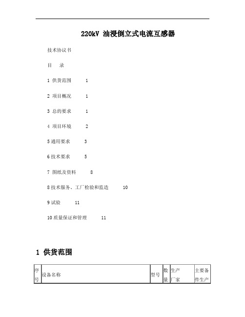
220kV 油浸倒立式电流互感器技术协议书目录1 供货范围 12 项目概况 13 总的要求 14 项目环境 25通用要求 36技术要求 57 图纸及资料 88技术服务、工厂检验和监造 109试验 1110质量保证和管理 111 供货范围注:额定扩大连续热电流标准值为120%,执行GB1208-2006。
2 工程概况规划180MVA主变压器2台,本期建设180MVA主变压器1台。
220kV规划出线6回。
本期建设220kV出线1回。
110kV规划出线12回。
本期110kV无出线。
35kV规划出线16回。
本期35kV无出线。
3 总的要求3.1 本技术协议书提出了对设备本体及其附属设备的技术要求。
主要包括设备的使用条件、主要技术参数、结构、性能、试验及所需技术资料等方面的内容。
3.2 本技术协议书提出的是最低限度的技术要求,并未对一切技术细节做出规定,也未充分引述有关标准的条文,供方应按有关标准提供符合IEC标准、国标、行标和本技术协议书的优质产品。
3.3 本技术协议书所使用的标准及规定的条款如遇到与供方所执行的标准不一致时,按较高标准执行。
3.4 本技术协议书经供需双方确认后,作为合同的附件,与合同正文具有同等的法律效力。
3.5 本技术协议书中涉及有关商务方面的内容,如与合同的《商务部分》有矛盾时,以《商务部分》为准。
3.6 本技术协议书未尽事宜,由三方协商确定。
4 项目环境4.1 海拔:1380m。
4.2 环境温度最高气温:+39.7℃最低气温: -33.1℃最大日温差:25K4.3最大日平均相对湿度(25℃时):95%,最大月平均相对湿度(25℃时):90%4.4日照强度:0.1W/cm2(风速0.5m/s)4.5覆冰厚度: 10 mm。
4.6最大风速: 30m/s(离地面10m、10分钟平均值)。
4.7耐震能力地震烈度 8度水平加速度: 0.25 g。
垂直加速度: 0.125 g。
共振、正弦拍波试验法,激振5次,每次持续时间5个周波,各次间隔2s,加速度应计及设备支架的动力放大系数1.2,并考虑其端部连接导线振动和导线张力的影响。
Fluke3310柔性电流探头详细介绍

工作电压 (见“安全标准”部分)
1000 V 交流有效值或直流
常规特性
探头和电缆材质
Alcryn 2070NC,加强绝缘, UL94 V0,颜色:红色
接合处材质
Lati Latamid 6H-V0 尼龙
探头电缆长度 探头电缆直径
610 mm (24 in.) 3310-PR 1220 mm (48 in.) 33112-PR
®
3310-PR/3312-PR
Flex Current Probe
说明书
简介
Fluke 3310-PR 和 3312-PR 柔性电流探头(以下简称作“探头”) 是采用 Rogowski 原理的交流电流探头。这些探头可配合 Fluke 1750 电力质量记录仪用于在极低频率到 15 kHz 范围之内测 量电流。灵活轻巧的测量头让用户可以快速方便地在不易接近的 区域中进行安装,适合测量粗导线上的电流。 探头针对与 Fluke 1750 电力质量记录仪配套使用而设计。
12.4 mm (0.49 in.)
传感器弯曲半径(最小) 输出电缆 输出接头
38.1 mm (1.5 in.) 双芯屏蔽,3 m 长 LEMO 6 针公头连接器
工作温度范围 存放温度范围 工作湿度
-20 °C 至 +90 °C(-4 °F 至 +194 °F) -40 °C 至 +105 °C(-40 °F 至 221 °F) 15 % 至 85 %(非冷凝)
Fluke 公司保证本产品从购买之日起一年内,其材料和工艺均无任 何缺陷。本项保证不包括保险丝、一次性电池,或者因意外、疏 忽、误用、改装、污染及非正常情况下的操作或处理而造成的损 坏。经销商无权以 Fluke 的名义提供其它任何保证。若要在保修 期内获得保修服务,请与您最近的 Fluke 授权服务中心联系,以 获取有关产品退还的授权信息,并将产品及故障说明寄至该服务 中心。 本项保证是您唯一可以获得的补偿。除此以外,Fluke 不作其它任 何明示或隐含的保证,例如适用于某一特殊目的的隐含保证。 FLUKE 不应对基于任何原因或推测的任何特别、间接、偶发或后 续的损坏或损失负责。由于某些州或国家不允许将隐含保证或偶 发或后续损失排除在外或加以限制,故上述的责任限制或许对您 不适用。