四轮独立驱动电动汽车驱动力最优控制方法
电动汽车动力系统中的优化控制策略使用技巧

电动汽车动力系统中的优化控制策略使用技巧随着环境意识的提高和能源危机的日益加剧,电动汽车作为一种清洁、节能的交通工具正在逐渐普及。
然而,要使电动汽车在性能、续航里程和充电效率等方面与传统燃油车相媲美,就需要对电动汽车的动力系统进行优化控制。
本文将介绍一些优化控制策略使用的技巧,以提高电动汽车的性能和效率。
首先,电动汽车的动力系统由电机、电池和控制器构成。
优化控制策略可以通过调节电机的转矩和转速,使得电动汽车在不同驾驶条件下的性能表现更为出色。
其中,矢量控制是一种常见的优化控制策略。
它通过独立控制电机的磁场和转子位置,实现对电机转矩和转速的精确控制。
这种控制策略可以提高电机的响应速度和输出功率,并降低能量损耗。
另外,电池是电动汽车的能源储存装置,对电动汽车的性能和续航里程有着重要影响。
为了实现最佳的电池使用效果,一种常用的优化控制策略是动态功率管理。
通过监测电池的电荷状态和负载需求,动态调整电池的充电和放电策略。
例如,在车辆需求较低时,可以选择将电池的功率限制在较低水平,以延长电池的使用寿命。
而在车辆需求较高时,可以提高电池的放电速度,以增加汽车的动力输出。
此外,为了提高电动汽车的充电效率,可以使用一种名为“峰值负荷削峰”的优化控制策略。
该策略通过识别电动汽车充电站的充电峰值需求时段,并根据需求的峰值选择合适的充电功率进行充电。
例如,在峰值需求时段,可以选择较低的充电功率,以避免充电站的负荷过大。
而在非峰值需求时段,可以选择较高的充电功率,以提高充电效率。
这种策略可以有效降低充电成本,并优化电动汽车充电站的资源利用率。
另外,为了增加电动汽车的能量回收效率,可以使用一种名为“再生制动”的优化控制策略。
该策略通过将电动汽车的动力系统转变为发电机,将制动过程中产生的能量转换为电能并储存到电池中。
这种策略可以提高电动汽车的整体能量利用效率,延长续航里程,并减少对电池的充电需求。
此外,为了提高电动汽车的行驶安全性和舒适性,可以使用一种名为“智能巡航”的优化控制策略。
四轮独立电驱动车辆全轮纵向力优化分配方法

ISSN 1000-0054CN 11-2223/N 清华大学学报(自然科学版)J T singh ua Un iv (Sci &Tech ),2009年第49卷第5期2009,V o l.49,N o.5w 25http://qhx bw.chinajo 四轮独立电驱动车辆全轮纵向力优化分配方法邹广才1,2, 罗禹贡1, 李克强1(1.清华大学汽车安全与节能国家重点实验室,北京100084;2.北京汽车研究总院,北京100176)收稿日期:2008-06-20基金项目:国家“八六三”高技术项目(2006AA11Z217)作者简介:邹广才(1979—),男(汉),吉林,博士研究生。
通讯联系人:李克强,教授,E -mail :likq @tsin ghua .edu .cn摘 要:为了充分发挥四轮独立电驱动型式在直接横摆力矩控制系统中对改善车辆动力学性能的优势,提出了一种新的全轮纵向力优化分配方法。
基于四轮独立驱动特点建立了侧重提高稳定性和侧重改善机动性的两种目标函数,分别用于降低整车路面附着负荷和降低整车横摆响应滞后。
综合直接横摆力矩需求、地面附着及电机驱动限制得出全轮纵向力优化分配的约束条件。
基于模糊理论设计了以车辆质心侧偏角为变量的权重函数,并对约束优化两种目标函数得出的纵向力分配值进行实时动态调整。
该方法进一步提高了车辆在直接横摆力矩控制下的整车路面附着潜力并改善横摆响应速度,提升了车辆稳定性和机动性。
关键词:四轮独立电驱动;直接横摆力矩控制;优化分配;电动汽车中图分类号:U 27文献标识码:A文章编号:1000-0054(2009)05-0111-05Tire longitudinal forces optimizationdistribution for independent 4WD EVZO U G uangcai 1,2,LUO Yugong 1,LI Keqian g 1(1.State Key Laboratory of Automotive Safety and Energy ,T s inghua University ,Beij ing 100084,China ;2.Beijing Automotive Technology Center ,Beij ing 100176,China )Abstract :A tire lon gitudinal forces op tim ization distribution meth od w as developed to take fu ll advantage of the four w heel in dependen t electr ic drive chas sis wh en DYC work ing.Bas ed on the ch aracteristics of fou r w heel independent electric drive chass is,tw o kinds of target indexes wh ich respectively took EV s tability and EV maneu verability as top-priority w ere d esig ned.One aimed to increase the vehicle grip margin and th e other aimed to qu icken the veh icle yaw respons e.Th ese tw o target indexes w ere respectively cons trained optimized under th e con straining conditions w hich were ded uced w ith DYC requir ement and the limit of r oad adhesion and the motor traction ab ility.T he fu zzy w eighting us ing th e s ide slip an gle w as designed to dynam ically regulate the optimization res ults to increase th e vehicle-road adhes ion potential and decreas e the veh icle yaw m otion delay.Key words :four wh eel in dependent electric drive;direct yawmoment control;optimization distribu tion ;electricvehicle四轮独立电驱动底盘可在满足整车控制要求的同时灵活分配各车轮纵向力,结合电机转矩响应快速准确易控的优势,进一步改善车辆在直接横摆力矩控制(direct yaw mo ment co ntrol ,DYC )作用下的动力学性能,具有很高的研究和应用价值。
四轮独立驱动电动汽车最小转弯能耗转矩优化控制研究

四轮独立驱动电动汽车最小转弯能耗转矩优化控制研究与传统内燃机驱动的车辆相比,新能源和混合动力汽车以其低能耗和低污染,成为目前汽车领域的一个重要研究方向。
在新能源汽车的众多构型中,各个车轮分别由电机驱动的四轮独立驱动电动汽车,由于其空间布置灵活,转矩解耦,以及驱动模式多样化而日益受到学者们的关注。
四轮独立驱动电动汽车的一个关键控制技术,就是各个车轮的转矩优化控制,而目前大多数的研究都停留在利用转矩差所产生的直接横摆力矩来提高车辆的侧向稳定性,从而提高车辆的操纵稳定性。
本文主要着眼于转矩优化控制对车辆弯道工况的能耗影响,旨在利用转矩定向分配控制策略实现车辆弯道工况的最小转弯能耗的需求,有效的提高整车经济性。
本文首先利用MATLAB/Simulink仿真软件,搭建了四轮独立驱动电动汽车车辆动力学模型、轮毂电机模型和驾驶员模型等,并利用现有商用软件CarSim对模型的准确度进行了验证,为后文的理论分析及仿真试验提供了可靠的仿真平台。
为了从原理上说明车辆转弯的受力机理,本文利用三自由度车辆动力学模型进行了建立了车辆的运动微分方程,基于转弯降速现象,说明了转弯阻力的产生机理和影响因素,同时提出了通过转矩定向分配控制技术来抑制转弯阻力的控制方法。
本文通过仿真分析,验证了转弯阻力的存在以及其对车辆动力性和能耗的影响。
通过研究发现车速和前轮转角是对转弯阻力影响最大的两个因素。
通过仿真验证,可以清楚的说明采用转矩定向分配控制技术,主动的调节车辆内外侧车轮的驱动转矩,在不改变车辆的行驶状态的同时,可以有效的降低车辆的转弯阻力,从而降低车辆驱动的需求功率,实现节能控制。
本文还对比了车辆不同驱动模式下的能耗情况,明确了车辆转弯工况下的前轮模式受到的转弯阻力小。
本文还通过仿真验证,证明了转矩定向分配控制技术可以改变车辆的转弯特性,有效的改善车辆的转向不足特性,提高车辆的转弯机动性。
为了确定弯道工况以经济性为目标的转矩轴间分配系数k,前轴内外侧车轮转矩分配系数k_f和后轴内外侧车轮转矩分配系数k_r,本文采用遗传粒子群混合优化算法,综合考虑弯道工况经济性和稳定性的影响,构建了最小转弯能耗的转矩优化控制策略,对转矩分配系数进行离线优化,制定出了基于车辆动力学模型的最小转弯能耗转矩分配系数表,同时本文确定出了不同弯道工况的转矩优化控制的最佳节能贡献度。
关于四轮独立驱动电动汽车的电机控制策论
1202IEEE TRANSACTIONS ON CONTROL SYSTEMS TECHNOLOGY, VOL. 20, NO. 5, SEPTEMBER 2012Fast and Global Optimal Energy-Efficient Control Allocation With Applications to Over-Actuated Electric Ground VehiclesYan Chen and Junmin Wang, Member, IEEEAbstract—This paper presents a fast and global optimization algorithm for an energy-efficient control allocation (CA) scheme, which was proposed for improving the operational energy efficiency of over-actuated systems. For a class of realistic actuator power and efficiency functions, a Karush-Kuhn-Tucker (KKT)-based algorithm was devised to find all the local optimal solutions, and consequently the global minimum through a further simple comparison among all the realistic local minima and boundary values for such a non-convex optimization problem. This KKT-based algorithm is also independent on the selections of initial conditions by transferring the standard nonlinear optimization problem into classical eigenvalue problems. Numerical examples for electric vehicles with in-wheel motors were utilized to validate the effectiveness of the proposed global optimization algorithm. Simulation results, based on the parameters of an electric ground vehicle actuated by in-wheel motors (whose energy efficiencies were experimentally calibrated), showed that the proposed global optimization algorithm was at least 20 times faster than the classical active-set optimization method, while achieving better control allocation results for system energy saving. Index Terms—Electrical ground vehicles (EGVs), energy-efficient control allocation (EECA), global optimality, in-wheel motors, Karush-Kuhn-Tucker (KKT) conditions, over-actuated systems.I. INTRODUCTIONOVER-ACTUATED systems, in which the number of actuators is greater than the degrees of freedom, have attracted increasing attention in recent years [1]–[5]. Many existing physical systems, such as marine vessels [6], [7], airplanes [8]–[10], and ground vehicles [11]–[16], [34], can be classified as over-actuated systems because redundant actuators are utilized to improve system performance, reliability, and reconfigurablity. In order to coordinate the redundant actuators and control the over-actuated systems in an elegant configuration, the main challenge is how to handle the actuator redundancy and physical constraints simultaneously. Control allocation (CA),Manuscript received October 06, 2010; revised February 20, 2011; accepted July 05, 2011. Date of publication August 12, 2011; date of current version June 28, 2012. This work was supported by Office of Naval Research (ONR) Young Investigator Award under the Grant N00014-09-1-1018, Honda-OSU Partnership Program, and OSU Transportation Research Endowment Program. Recommended by Associate Editor F. Basile. The authors are with the Department of Mechanical and Aerospace Engineering, The Ohio State University, Columbus, OH 43210 USA (e-mail: wang. 1381@). Color versions of one or more of the figures in this paper are available online at . Digital Object Identifier 10.1109/TCST.2011.2161989as a feasible and promising method, is commonly employed in over-actuated systems to optimally allocate the desired virtual (generalized) controls among all the available actuators within their respective constraints, see surveys [6], [9], and the references therein. Several different CA algorithms, such as direct allocation [17], daisy-chain allocation [18], (redistributed) pseudo-inverse allocation [14], [19], optimization-based allocation [8], and adaptive control allocation [20] (which was later applied to vehicle control simulations in [21]) have been proposed based on different methods of distributing the virtual controls to the redundant actuators. Although the aforementioned CA methods have different strengths and limitations, numerical optimization-based algorithms are becoming more and more widely used in CA [7], [8], [13], [22]–[26]. Sørdalen [7] adopted the magnitude of actuation as a secondary optimization term in CA formulation in order to achieve minimum control effort. Bodson [8] summarized and evaluated error minimization, control minimization, and mixed error and control optimization problems for optimization-based CA methods. Härkegård [22] suggested a dynamic CA method by penalizing virtual control at a previous sampling time in the secondary optimization term. Zaccarian [24] described a dynamic CA by inserting a dynamic system as an allocator between the high-level controller and low-level actuators. Moreover, Johansen et al. [25] resolved a CA problem on ship control by decomposing a non-convex thrust region into multiple convex sets, solved by mixed-integer-like convex quadratic programming. Within the aforementioned optimization-based allocation methods, the optimal algorithms for solving various CA problems were similar although the problem formulations were different. Standard numerical algorithms, such as quadratic programming, active-set, and fixed-point, were applied to solve various nonlinear programming problems of CA. However, local minima are often obtained by adopting these standard numerical algorithms for general nonlinear programming CA problems. On the other hand, the selections of the initial conditions of these standard algorithms also strongly influence the acquisition of the global minimum. Although there are no uniform optimization algorithms for general nonlinear programming problems, this paper proposes a global and initial-condition-independent algorithm for energy-efficient CA [27] based on the Karush-Kuhn-Tucker (KKT) conditions. In the expression of energy-efficient CA problem, a special nonlinear programming is considered since the secondary optimization term, standing for the system power consumption,1063-6536/$26.00 © 2011 IEEECHEN AND WANG: FAST AND GLOBAL OPTIMAL ENERGY-EFFICIENT CONTROL ALLOCATION1203consists of polynomial and/or fractional functions. By utilizing this kind of characteristics, the nonlinear programming procedure for energy-efficient CA can be transferred into classical eigenvalue problems, which are initial-condition-independent, based on the KKT conditions. Thus, all the physically meaningful eigenvalues are obtained as local minima of the energy-efficient CA problem. Through simple comparisons and exclusions, a global minimum can be obtained. The main contributions of this paper are: 1) a novel energy-efficient control allocation scheme which can explicitly incorporate actuator efficiencies and actuator operating modes into the control allocation for over-actuated systems and 2) a fast and global algorithm for solving the non-convex optimization problems associated with the proposed energy-efficient CA scheme. The remainder of this paper is organized as follows. In Section II, both single-mode and dual-mode energy-efficient CA schemes are described. The KKT condition-based algorithm is proposed to find the global minimum for the energy-efficient CA in Section III. In Section IV, numerical examples are given to verify the effectiveness of the proposed global optimization methods. In Section V, simulations based on longitudinal motion control of an electric ground vehicle actuated by in-wheel motors are presented to show the effectiveness of the proposed optimization algorithm in comparison to the standard active-set optimization algorithm. Conclusive remarks are presented in Section VI. II. ENERGY-EFFICIENT CONTROL ALLOCATION In this section, the main ideas and formulations of singlemode and dual-mode energy-efficient CA are briefly described. For more details and discussions on the energy-efficient CA, the reader can refer to the authors’ work [27]. A. Single-Mode Energy-Efficient CA A general over-actuated dynamic system is described as follows: (1) , where the system state vector is represented by is the system output vector, is the virtual control is the control effectiveness matrix, and vector, is the control input vector. Note that when the relaand is nonlinear, the control effectivetionship between ness matrix can be obtained by local approximation with an affine mapping through linearization at each sampling instant holds as the number [28]. For over-actuated systems, of actuators is greater than the number of virtual control signals and the number of the controlled system outputs. Thus, there is no unique solution for in general and CA is often utilized to optimal mapping problem. address the For over-actuated systems in which each actuator has only one actuation mode and one corresponding energy efficiency function, the energy-efficient control allocation is formulated as (2) s.t.where is the total instantaneous power consumption by all the actuators. The actuator amplitudes’ lower and upper bound and in a component-wise vectors are represented by fashion, respectively. Such magnitude bounds can also incorporate the actuator rate limitations based on the given system sampling period and difference formulation, see [22] and [27] for details. A small positive parameter is used to balance the efforts between reducing CA errors and the power consumptions. Note that smaller parameter will yield less CA errors [8]. Small CA errors may not noticeably affect the overall system control performance. Moreover, a high-level robust controller can help to overcome/mitigate the influence of the limited CA errors in the mixed optimization formulation. The system power consumption can be a function of actuator force or torque values based on the corresponding actuator efficiency functions, which can be expanded as follows: (3) Within (3), and are the output power function and the efficiency function of the th actuator, respectively. and represents Therefore, the division between . Thus, the formulathe th actuator’s power consumption tion of single-mode energy-efficient CA is developed by (2) and (3). B. Dual-Mode Energy-Efficient CA When actuators in physical systems have dual operating modes, such as consuming and gaining energy, and different associated efficiency functions, the energy-efficient CA becomes more challenging. For such dual-mode actuators, their effects on the virtual control, magnitude/rate constraints, efficiencies, power consumption, or gain characteristics may vary with operating modes. Consequently, to achieve energy-efficient CA for systems involving dual-mode actuators, the actuator mode selections need to be seamlessly integrated into the CA scheme as well since the dual-mode actuators with different modes/amplitudes may construct the same virtual control signal with different energy consumptions. Thus, the energy-efficient CA scheme needs to dictate not only the magnitude but also the operating mode for each of the redundant actuators in an optimal way. Such a requirement cannot be satisfied by the existing standard CA schemes and thus represents a key challenge for extending the foregoing energy-efficient CA to physical systems whose actuators have dual actuation modes. Here, a virtual actuator concept is introduced for tackling such a challenge. The expression of over-actuated dynamic systems described in (1) is correspondingly augmented as (4) A virtual actuator control input vector , is introduced to represent the of actuators who have dual operating modes in the system. This virtual actuator augment systematically incorporates the dual-mode actuators into the energy-efficient CA scheme. Such a method enables the CA to seamlessly dictate both actuators’ magnitudes and operating1204IEEE TRANSACTIONS ON CONTROL SYSTEMS TECHNOLOGY, VOL. 20, NO. 5, SEPTEMBER 2012modes, resolving the aforementioned challenge. The augis the new control mented matrix effectiveness matrix for the new system. Note that the matrix are determined by the dual-mode actuators. The energy-efficient CA scheme (2) is modified for the new augmented system (4) with dual-mode actuators as (5) s.t. Since a particular dual-mode actuator can only operate in one of the two operating modes at a given time instant, the added third term in the constraints ascertains that only one operating mode is assigned to a physical actuator by the energy-efficient CA. Electric motors such as the in-wheel motors equipped on electric ground vehicles can be classified as dual-mode actuators. In electric ground vehicles, the electric motors can either work in motor (driving) mode, in which motor consumes onboard electric energy or generator (regenerative braking) mode, in which motor produces electric energy from the vehicle kinetic energy. thus can include Within (5), the total power consumption the instantaneous power consumption and gain with respect to the dual operating modes for each of the physical actuators. For example, if denotes the actuator energy consuming mode and represents the actuator energy gaining mode, then the total power consumption of all the actuators in different modes is formulated as (6) Within (6), and denote the actuator output power and and efficiency at the energy consuming mode while represent the actuator input power and efficiency at the energy gaining mode, respectively. The energy gaining mode is inferred by the minus sign in front of virtual actuator power consumption. Therefore, the formulation of the dual-mode energy-efficient CA is built by (5) and (6). III. KKT-BASED GLOBAL OPTIMIZATION ALGORITHMS FOR ENERGY-EFFICIENT CONTROL ALLOCATION For both single-mode and dual-mode energy-efficient CA, the authors adopted a standard nonlinear optimization method, active-set algorithm, to obtain the solutions [27]. The adopted active-set algorithm, however, cannot guarantee the global optimization and is sensitive to the selections of initial conditions. Based on the KKT conditions, a global and initial-condition-independent optimization algorithm for the energy-efficient CA is proposed as follows. A. KKT Conditions and Algorithm for the Single-Mode Energy-Efficient CA In order to develop the optimization algorithm for the singlemode energy-efficient CA, the expressions (2) and (3) are combined and modified as (7)s.t. The square modification for CA errors is convenient for derivatives of the Lagrangian function defined later. are the vector forms of output power functions and efficiencies, respectively. Define the following Lagrangian function: (8) Within (8), nonnegative vectors and are the Lagrangian multipliers. Based on the KKT conditions [29], the optimal solution with certain Lagrangian multipliers and satisfy the following conditions:(9)Remark 1: Generally, the KKT conditions are necessary conditions for local minima. They can also be utilized to sufficiently characterize the global optimal solution when the objective/cost function and the constraint set are convex. Although the cost function in (7) is not in a convex form, further examinations can be fulfilled to exclude the maximum and the local minima. The calculations on optimal control are categorized by the values of Lagrangian multipliers and . When the Lagrangian mul, the control can be calculated within tipliers and/or boundaries by solving the algebraic equations (9). For the special form of energy-efficient CA, the secondary optimization term is a sum of fractions, whose denominators and numerators can be characterized by low-order polynomial functions of power and efficiency, making (9) be easily solvable. When the and/or , the control Lagrangian multipliers has to be equal to the boundary values and/or based on the KKT conditions. Thus, a few local minima including the boundary values can be obtained from the above two categorized steps. At last, further comparisons among these local minima based on the criteria of the least power consumption can give the global minimum. In sum, the algorithm is written in a pseudo-code form as follows. Inputs: and are from the system model and high-level • controller. , , , and are from actuator models • and experimental calibrations. and are adjustable parameters for optimization. • Steps: 1) Set , solve algebraic equations (9) and obtain all the nontrivial local minima .CHEN AND WANG: FAST AND GLOBAL OPTIMAL ENERGY-EFFICIENT CONTROL ALLOCATION12052) Set , consequently obtain and , can be obtained by solving the other the remaining algebraic equations in (9), like the process in step 1. , consequently obtain 3) Similar to step 2, set and , the other can be obtained by solving the left algebraic equations in (9), like the process in step 1. 4) Calculate the total power consumptions (the second term obtained from the above three steps, in (7)) for all the by comparison. and obtain the global optimal B. KKT Conditions and Algorithm for the Dual-Mode Energy-Efficient CA Similar to the single-mode energy-efficient CA case, the expressions (5) and (6) are combined and modified so as to develop the optimization algorithm for the dual-mode energy-efficient CA(10)s.t.Remark 2: Again, although the KKT conditions, which are necessary for local minima, generally cannot guarantee the global optimal solution of the non-convex cost function (10), further examinations can be fulfilled to exclude the maximum and and the local minima. The calculations on control are categorized by the values of Lagrangian multipliers , , , and . When the Lagrangian multipliers and/or ( and/or ), the control can be calculated within boundaries by solving the algebraic (12). The special secondary optimization term in (10) consists of a sum of polynomials and fractions, whose denominators and numerators can also be characterized by low-order polynomial functions of power and efficiency, making (12) be readily solvable. Moreover, the complementary condition determines that and cannot be nonzero simultaneously, which can be further applied to reduce the computational cost and . When the Lagrangian of (12) by setting multipliers and/or ( and/or ), has to be equal to the boundary values. the control Thus, a few local minima including the boundary values can be obtained from the above two categorized steps. At last, further comparisons among these local minima based on the criteria of the least power consumption can give the global minimum. Similar to the single-mode CA case, the algorithm for dual-mode CA is given in a pseudo-code form as follows: Inputs: • and are from the system model and high-level controller. , , , , , , and • are from actuator models and experimental calibrations. • and are adjustable parameters for optimization. Steps: , solve algebraic equations 1) Set and . (12) and obtain all the nontrivial local minima can be Note that the complementary condition applied to simplify the calculation of (12) by categorizing , and , the whole process into ( are trivial cases without solving (12)). 2) Set , consequently obtain and , through the complementary and furthermore . The other and condition can be obtained by solving the remaining algebraic equations in (12), like the process in step 1. , consequently obtain 3) Similar to step 2, set and , and furthermore through . The other the complementary condition and can be obtained by solving the left algebraic equations in (12), like the process in step 1. and , obtain 4) Repeat steps 2 and 3 for and . 5) Calculate the total power consumptions (the second term and obtained from the above in (10)) for all the and by steps, and find out the global optimal comparison.where are the vector forms of input power functions and efficiencies, respectively. Define the corresponding Lagrangian function as(11) Within (11), nonnegative vectors and , and , are the Lagrangian multipliers. Based on the KKT conditions and with certain Lagrangian [29], the optimal solutions , and satisfy the following conditions: multipliers , ,(12)1206IEEE TRANSACTIONS ON CONTROL SYSTEMS TECHNOLOGY, VOL. 20, NO. 5, SEPTEMBER 2012Fig. 1. Experimentally measured efficiency curve of an in-wheel BLDC motor and its controller. Fig. 2. Driving efficiency map of an in-wheel BLDC motor and its controller based on experimental data. TABLE I IN-WHEEL MOTOR EFFICIENCY FUNCTION PARAMETERSmotor speed also slightly affects the motor efficiency as can be seen from the measured experimental data shown in Fig. 2, the efficiency curves are similar within a large range of motor rotational speeds [31]. Moreover, motor rotational speed can be reasonably assumed to be a constant at each instantaneous time for CA due to the short sampling period. The power consumption of the in-wheel motor is given by It should be noted that as the number of the system redundant actuators increases, the computational effort and complexity of the preceding algorithms will grow as well. In addition, the actuator efficiency function characteristics also influence the complexity of the KKT-based energy-efficient CA algorithm. IV. NUMERICAL EXAMPLES AND DISCUSSIONS In this section, the aforementioned KKT-based algorithms for both single-mode and dual-mode energy-efficient CA are applied to numerical examples. These examples, generated from in-wheel motor models and experimental data, verify the assumption and validation of the aforementioned formulation. of an in-wheel brushless The output efficiency function DC (BLDC) motor and its controller is expressed by fitting the experimental data [31] shown in Fig. 1. Two linear functions are adopted to approximate the rising and falling potions of the entire experimentally measured data (13) , , , and are coefficients, listed in Table I. where Multiple reasons make the piece-wise linear function (13) as the efficiency fitting function. The first one is the consideration of computational effort. From either (9) or (12), the KKT conditions offer algebra equations or eigenvalue problems to obtain the optimal values. The simpler efficiency fitting function makes the computational cost less. It can be seen later that this piece-wise division actually makes the global optima obtainable. The second reason is due to the DC characteristics of the brushless DC motors. The piece-wise linear function (13) can sufficiently describe the rising and falling trends along with the increase of motor torque. Last but not the least, although the (14) is a given rotational speed and stands for the motor where torque. Without loss of generality, two in-wheel BLDC motors are considered for the longitudinal speed control of a bicycle vehicle model under straight line driving condition. Different scaling ratios were applied to the efficiency curve in Fig. 1 to generate different efficiency functions for two motors and two operating modes. In the case of single-mode actuation (both in-wheel motors drive), the control effectiveness matrix is . In the case of dual-mode actuation (both in-wheel motors can perform driving and regenerative braking), the control . The boundaries of the effectiveness matrix is 0 Nm and 100 Nm for driving, and actuator are 100 Nm and 0 Nm for regenerative braking. A. Single Mode Energy-Efficient CA In the numerical example for single-mode energy-efficient 400 rpm, CA, the motor rotational speed was selected as which is about 50 km/h for a passage car with a common tire effective radius around 0.3 m. The penalty coefficient was set was set to be an idento be 0.001 and the weighting matrix tity matrix for the optimization problem. The scaling ratio for efficiency of the second in-wheel motor was 0.9. for nonSubstituting (14) into (9) and letting trivial solutions, the following equations are obtained:(15)CHEN AND WANG: FAST AND GLOBAL OPTIMAL ENERGY-EFFICIENT CONTROL ALLOCATION1207Fig. 3. Space of the total power consumption for single-mode energy-efficient CA with two in-wheel motors.Fig. 4. Power consumption of single-mode energy-efficient CA with two in-wheel motors with different given virtual control values.Since the efficiency function (13) is piece-wise linear, the equations in (15) have to be solved by combining different efficiency functions. Basically, four pairs of two algebraic equations are obtained. In order to solve two algebraic equations with two variables, like (15), variable cancellation can obtain the equivalent problem of finding the roots of a polynomial due to the simple efficiency and power expressions (13) and (14). The obtained polynomial can be taken as a characteristic polynomial of a classical eigenvalue problem. Thus, the optimization problem are transferred into four (two pairs of) eigenvalue problems to and . Compared with the trivial solutions find optimal (boundary values of actuators), the global minimum can be finally obtained. In order to show the real global minimum is achieved, the space/surface of the total power consumption, the secondary optimization term in (7), is plotted in Fig. 3. As shown in Fig. 3, the total power consumption generally becomes larger with the increase of motor torque. However, due to the non-convex characteristics of the surface, it is hard to find the global minimum by using standard optimization algorithms. Through the piece-wise fitting for the efficiency functions of the actuators, the non-convex space/surface is actually , each of which is convex divided into four portions within its own definitional area. Thus, in each area, the corresponding global minimum can be obtained through KKT conditions, which is equivalent to an eigenvalue problem. Then, a simple comparison among these global minima and boundary values of different areas can suggest the true global minimum in the entire non-convex space of the power consumption. The five lines on the surface stand for different virtual control values, which are the intersection curves between the non-convex power consumption surface and vertical planes, corresponding to dif. These curves define the solution sets of ferent problem (7) under different virtual control signals without considering the power minimization. Given different virtual control , we can clearly observe the global optimization of the distribution torques and from the plot in Fig. 4. Fig. 4 shows the power consumption of optimization problem (7) by inserting efficiency and power expressions in (13) and (14). Each curve in Fig. 4 represents different virtual controlsignals from 10, 20, 40, 60, to 80 Nm. On each curve, the corresponding virtual control is equal to the sum of distributions onto the two motors. All the labels in Fig. 4 represent the global optimization points. Although these global minimum points vary on the non-convex curves, the proposed KKT-based algorithm accurately found all of them from the equivalent eigenvalue problems and simple comparisons with boundary values. If a standard active-set algorithm is applied to solve the nonlinear optimization problem, the global minimum points may not be found by inappropriate choices of initial conditions and only local minima can be obtained. It is interesting to observe the 40 Nm. The global optimum dictates that the equal case of torque distribution gives the lowest power consumption, which happens to be the distribution result of a standard CA method [27]. This is because the most efficient operating point lies on 20 Nm, which can be seen from Fig. 1 and the efficiency scaling factor. B. Dual-Mode Energy-Efficient CA The same values for motor rotational speed , weighting maand the penalty coefficient as those in the single-mode trix case were adopted for the numerical example in dual-mode energy-efficient CA. Assuming that two in-wheel motors (front and rear) have similar efficiency profiles, the scaling ratio for the driving efficiency of the rear motor was 0.9. Moreover, the motor regenerative braking efficiency is usually less than the driving efficiency. Thus, the scaling ratio for the regenerative braking efficiency of each motor was set as 0.9 of the corresponding driving efficiency. Substituting (14) into (12) and letting for nontrivial solutions, the following expressions are obtained:1208IEEE TRANSACTIONS ON CONTROL SYSTEMS TECHNOLOGY, VOL. 20, NO. 5, SEPTEMBER 2012Fig. 5. Space of the total power consumption for dual-mode energy-efficient CA with two in-wheel motors.Fig. 6. Power consumption of dual-mode energy-efficient CA with two in-wheel motors with different given virtual control values.(16)Fig. 7. EGV longitudinal speed tracking control structure.Note that although four algebra equations and two complemenand tary equations are listed in (16), the four equations for or and cannot be held simultaneously due to two complementary equations. Thus, the two complementary equations can be logically applied to reduce the computational cost since only two algebra equations are solved together. Like the process in the single-mode case, similar steps are implemented to solve (16) for local minima by plugging in the piece-wise linear efficiency function (13). Then, comparisons among local minima and trivial solutions (boundary values) will give the globally optimal solutions. In order to show the real global minimum is achieved, the space/surface of the total power consumption, the secondary optimization term in (10), is plotted in Fig. 5. As shown in Fig. 5, the power consumption space becomes more non-convex than that in the single-mode case. Since each virtual actuator has two piece-wise linear efficiency potions, the total non-convex power space consists of sixteen convex . However, for a certain virtual control value, areas only parts of the convex areas are meaningfully involved in. Fig. 5 shows that seven convex surfaces are physically achiev20 Nm. Thus, similar to the single-mode case, a able when simple comparison among global minima and boundary values of different areas can suggest the true global minimum in the entire non-convex space. The four lines on the surface stand for different virtual control values, which are plotted in Fig. 6 to clearly show the global minimum for the torque distribution and . among Fig. 6 shows the power consumption of the optimization problem (10) by inserting efficiency and power expressions in (13) and (14). Each curve in Fig. 6 represents different virtual control values from 4, 8, 10, to 20 Nm. On each curve, the corresponding virtual control is equal to the sum of distributions on the two motors. All the labels in Fig. 6 represent the global optimal points. Although these global minimum points vary on the non-convex curves, the proposed KKT-based algorithmaccurately finds all of them from the equivalent eigenvalue problems and simple comparisons with the boundary values. V. SIMULATIONS OF ELECTRIC GROUND VEHICLES In this section, the proposed KKT-based algorithm for both single- and dual-mode energy-efficient CA are applied to an electrical ground vehicle (EGV) model equipped with front/rear in-wheel motor sets. Electric concept cars with independently actuated in-wheel motors such as the GM Geo Storm and Volvo ReCharge have already proceeded into the prototyping and/or pre-market phases. Thus, in-wheel motors have potential applications in automotive industry, see [13], [27], and reference therein. Compared with the conventional vehicle drivetrain architectures where driving and braking of different wheels are coupled, EGVs with independently actuated in-wheel motors can offer higher control flexibility and many potential advantages. Consequently, the efficiency and control allocation problem are meaningful to be investigated. Note that the proposed energy-efficient CA schemes are applicable for many over-actuated systems, well beyond the electrical/hybrid vehicles. Moreover, such general energy-efficient CA methods are different from the power management methods for hybrid vehicles [32], [33] because of the distinctions in number and characteristics of actuators as well as the control purposes for over-actuated systems. The structure for vehicle longitudinal speed tracking control is shown in Fig. 7 for comparison between the common active-set method and the proposed KKT-based algorithm. The and , desired and measured vehicle speed are denoted as respectively. The high-level speed tracking controller is a proportional plus integral (PI) controller, which generates the virtual control for the energy-efficient control allocator. Note that other high-level speed tracking controllers can be employed as。
四轮驱动电动汽车驱动方式控制系统设计

四轮驱动电动汽车驱动方式控制系统设计摘要作为电动汽车行业新颖的发展方向,四轮驱动电动汽车由于其理想的控制特性和良好的应用前景,受到学术和工程界的普遍关注,已经成为研究热点。
首先,根据整车参数和动力性的要求,计算出电机的功率、转速等主要指标,选定轮毂式无刷直流电机型号并进行简单的动力匹配。
再根据不同工况,选择适合电动汽车的驱动方式,构建四轮独立驱动电动车的驱动方式控制的系统模型。
其次,根据电动汽车行驶路面的路况和所处的工况,采用一定的控制策略和驱动策略,由切换电动机的工作状态,使电动汽车既可以在不同的工况(例如启动、爬坡及转弯)选择适应的驱动方式,又可以在不同等级的路面下(例如城市路面、高速公路)选择最佳的驱动方式,即做到电动汽车的即时四驱,从而最大程度地发挥电动汽车驱动方式控制的优点。
最后,本文通过建立数学模型,并利用matlab进行软件仿真,来对轮毂电机驱动力模型、整车模型以及控制策略模型这些模型进行仿真试验。
以上研究表明:四轮驱动是一种理想可行的驱动方案;本文建立的仿真模型合理实用。
关键词:四轮驱动;驱动方式控制;不同工况;轮毂式无刷直流电机Design of driving forms control systemof four-wheel drive electric vehicleAbstractThe four-wheel drive(4WD) EV is one of the developing directions for further EV. Because of its perfect Controlling performance and good application prospect in engineering, 4WD EV have been getting universal attention by both academicians and engineers.It also has become a research hotspot of research.Firstly,according to the requirements ofthe vehicle parameters and power performance,we need to calculate main indicators such as the motor power, rotational speed, and select the model for wheel-hub brushless DC motor. According to different working condition, we should choose suitable driving forms for EV, and build up the model of driving control system about four-wheel independent drive EV.Then,according to EV working condition of pavement, we need to adopt certain control strategy and drive strategy.By switching the working state of the motor, 4WD EV can not only work in different conditions (such as starting, climbing and turning) to choose adapted drive forms, but also under different levels of the road (such as urban roads, highways) to choose the best way of driving.Which achieve the real-time four-wheel drive for EV, so as to maximize the advantages of EV driving forms control.Finally,by establishing the mathematical models and using MATLAB to simulation,we can set up the simulation models for driving force models of wheel-hub motor, vehicle models and control strategy models. Above research shows that the 4WD is a kind of ideal andfeasible driving form; the simulation models in this paper is reasonable and practical.Key words:Four-wheel drive;The control of driving forms;Different working conditions;Wheel brushless DC motor目录1 绪论 11.1 课题研究背景 11.2 电动汽车国内外发展状况 11.2.1 国外发展状况 11.2.2 国内发展状况 21.3 电动汽车驱动方式控制的研究状况 31.4 本章小结 42 四轮电动汽车的驱动分析 52.1 电动汽车的行驶阻力 52.2 四轮电驱汽车的驱动力 62.3 四轮电驱汽车的受力特点 72.4 驱动电机的介绍 92.5 本章小结 113 四轮独立驱动电动汽车驱动模型的建立 12 3.1 永磁无刷直流电机特性分析 123.2 轮毂式永磁无刷直流电机模型 143.3 整车模型 173.3.1 电动汽车整车动力学模型的建立 17 3.3.2 纵向承载横向不承载车身结构 193.3.3 整车控制策略 203.4 本章小结 224 四轮电动汽车的驱动方式控制 234.1 驱动工况研究 234.1.1 平路工况 234.1.2 启动工况 254.1.3 加速工况 254.1.4 坡道工况 264.1.5 跛行工况 264.2 电动汽车驱动方式的控制 264.2.1 电动车几种简单的行驶状态 274.2.2 简单力学条件 284.2.3 复杂受力情况 294.2.4 电动汽车驱动方式应用情况 304.3 本章小结 325 四轮驱动电动汽车不同条件下的优化和仿真 33 5.1 电动汽车数据处理 335.2 模型仿真 366 总结和展望 47参考文献 48致谢 491 绪论1.1 课题研究背景电动汽车以车载电源作为动力,由电动机来驱动,符合交通法规等规定的车辆。
四轮独立转向电动汽车最优控制器设计
: 一  ̄ l E < r l +
=
( 4 )
2 . 2前馈控制 为 了 使 汽 车 在 行 驶 过 程 中 始 终 保 持 零 质 心 侧 偏 角 ,可 采 用 简 单 的 后 轮 转 角 比 例 于 前 轮 转角的方式 。对 于单轨摩托车模 型,令: ( 5 ) 式中, 6 、 6 为前后轮转 角, 6 为前后轮转角 比例系 数。 当 = 0 时,求得:
系统的状态反馈增益矩 阵为: 置: 盈 P ( 1 1 ) 四轮独立转 向系统最优控制规律为 :
=r+ AU =r一 P ( 1 2 )
状 态 反 馈 增 益 矩 阵K 是在性能指标J 最 小 6一 “ 2 的条件 下求得 的,而性能指标 取决于加权 和R 。Q 和R 选 取不同 ,会产 生不 同的控 一 _ 2 L i [ .  ̄ a r ( 6 ) 矩 阵Q a — — u 、 制 效果 ,质心侧偏 角和横摆角速度 对于 四轮 2 L C r 转 向 系 统 至 关 重 要 , 因 此 在 选 取 加 权 矩 阵 2 . 3反馈控制器 时,在兼顾系 统响应速度 的同时 ,还应考 虑 四轮独 立转 向控 制器 与质心侧 偏角偏 差 = 一 、横摆 角速度偏 差 e r = r ’ 一 r ,有着 直接 的 质心侧偏角尽 可能小 ,横摆 角速 度尽量符 合 联系 。四轮独立转 向线性模 型如公式 ( 7 ) 所示 : 参考模型理想值 。Q 中q 、q 取值的大小反 映 毒:Ae+B“ ( 7 ) 对 状态变 量e = [ r ] 中 某 一 量 的重 视 程 度 , 线性 二次型 最优 控制 问题是 是寻找 一个最优 的控 制信号u( t ) 使得 评价 函数 ,最 优控制 R中 R, 、R 取 值 的 大 小 决 定 了 对 于 输 入 器 性 能 指 标 函数 为 : “ = 哆 ] 中某 一 量 的 控 制 程 度 。 本 文选取 文献 [ 5 ] 中车 辆 参 数 , 取 车 速 { e r Q e + A u R A ( 8 ) 为l m / s 进 行 仿 真 , 经 过 反 复 比对 ,最 终 选 取 权值矩 阵元素 q 。 = 0 . 2, q = 0 . 1 , 且= 0 . 5、 1 ,状态 反馈矩 阵为 : ( 下转 第1 6 2 页)
四轮驱动电动汽车电机控制策略研究

四轮驱动电动汽车电机控制策略研究一、引言随着社会的发展,环保、节能已成为刻不容缓的问题。
而作为交通工具的汽车,也逐渐向环保、节能的方向发展,电动汽车成为了未来大力发展的领域。
作为电动汽车中的一员,四轮驱动电动汽车具有很强的越野性能和行驶稳定性,是非常适合户外使用的车型。
然而,由于四个轮子的转速往往不同,所以电机控制策略的设计和优化是十分关键的。
本文将从四轮驱动电动汽车的结构特点出发,分析其电机控制策略的设计方法,并阐述相关理论,为相关技术人员或爱好者提供一些参考和借鉴。
二、四轮驱动电动汽车的结构特点四轮驱动电动汽车有两个左右独立的电机系统,分别驱动前、后轴。
与传统的燃油汽车不同,四轮驱动电动汽车需要加装电机控制器。
整个电机控制系统主要包括驱动电机、行驶控制器和电池组三部分。
其中,驱动电机是四轮驱动电动汽车最重要的部分,是车辆行驶的动力来源。
而行驶控制器则是将电池的直流电转换为交流电,控制电机的转速和扭矩。
此外,电池组的容量也决定了四轮驱动电动汽车的续航能力和使用成本。
三、电机控制策略设计方法1. 电机控制器电机控制器是四轮驱动电动汽车中非常重要的一部分,其主要作用是控制电机的电流、电压和频率等参数。
这需要一个高精度的驱动器来实现。
一般来说,电机控制器的控制模式可以分为开关模式和恒流模式。
(1)开关模式开关模式是将电流通过调整开关的开关时间来实现的。
当开关开启时,电源电压就会通电到电机,从而使电机启动;当开关关闭时,电源电压就会被切断,电机就会停止运转。
(2)恒流模式恒流模式是将电流控制在一个预先设定的电流范围内,这种模式能够保证电机的转速和扭矩不会产生变化。
恒流模式主要适用于高速和高负载情况下的电机控制。
2. 电机控制策略电机控制策略主要包括电机控制器的选型、电机动力学模型的建立和控制方法的设计等方面。
(1)选型电机控制器的选型需要考虑电机的功率、转速、扭矩等方面的要求。
同时,还需要考虑电机控制器的响应速度、控制方式等因素。
一种极限工况下的四轮独立驱动电动汽车牵引力控制方法[发明专利]
![一种极限工况下的四轮独立驱动电动汽车牵引力控制方法[发明专利]](https://img.taocdn.com/s3/m/bc29cc3250e2524de4187e1a.png)
专利名称:一种极限工况下的四轮独立驱动电动汽车牵引力控制方法
专利类型:发明专利
发明人:殷国栋,沈童,任彦君,王金湘,梁晋豪,黄文涵,王凡勋,丁昊楠
申请号:CN202010851778.9
申请日:20200821
公开号:CN112026533A
公开日:
20201204
专利内容由知识产权出版社提供
摘要:本发明公开一种极限工况下的四轮独立驱动电动汽车牵引力控制方法,综合考虑了驾驶员的控制需求以及车辆的稳定性原则,采用三种不同的驱动模式取代了单一的转矩分配方式,最大程度地利用了轮胎的纵、侧向附着裕度,保证了四轮独立驱动电动汽车在低附着路面的运动跟踪精度和车身稳定要求,同时也使得上层控制目标和底层执行结果保持一致,方便了驾驶员在极限工况对车辆的操纵,提高了车辆的主动安全性。
申请人:东南大学
地址:211100 江苏省南京市江宁区东南大学路2号
国籍:CN
代理机构:北京德崇智捷知识产权代理有限公司
代理人:王斌
更多信息请下载全文后查看。
- 1、下载文档前请自行甄别文档内容的完整性,平台不提供额外的编辑、内容补充、找答案等附加服务。
- 2、"仅部分预览"的文档,不可在线预览部分如存在完整性等问题,可反馈申请退款(可完整预览的文档不适用该条件!)。
- 3、如文档侵犯您的权益,请联系客服反馈,我们会尽快为您处理(人工客服工作时间:9:00-18:30)。
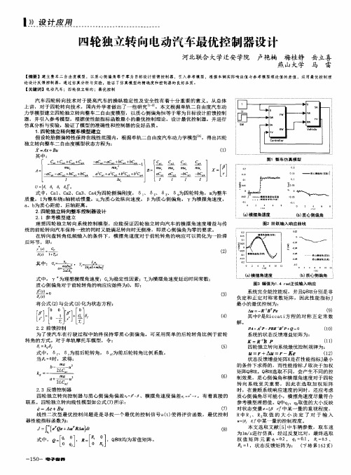
从图 2可以看出, 电机电流大约在 1 1s时达到 峰值, 而后逐渐减小, 最终稳定在 3 2A 左右。根据
式 ( 1) ~ 式 ( 4) 可知, 在系统受到阶跃输入时, Ua 增 大, 由于电机转速不能同步瞬时变大, Ea 与 Ua 之间 的差值增大, 致使 Ia 变大, 待电机转速上升后, Ea 与 Ua 之间差值恢 复到稳定 值时, Ia 逐 渐降低 趋于 稳 定, 这与阶跃实验相符。
图 4 整车控制方 法框图
前轮、右前轮、左后轮和右后轮驱动系统; r1、r2、r3 和 r4 分别为左前轮、右前轮、左后轮和右后轮驱动系统 的参考输入。
如图 4所示, 无论采用何种驱动力分配策略, 其 目的都是得到当前状 态下每个驱动 电机的理想 电
流, 与当前电机实际电流的差即为当前电机的偏差
量, 通过控制器作用, 将偏差量调整为零, 即达到控 制目的。从图 4可知, 每个驱动系统控制器由参考
式。具体方法为先将车辆置于平坦的道路上, 分别 以低、高两种速度行驶, 通过调整四轮控制输入将四 轮驱动电机电流调节为相等, 记录两种速度工况下 各驱动电机的 D /A 控制量, 并以此作为阶跃实验时 各驱动电机阶跃控制量。图 2为左前轮电机阶跃响 应电流和驱动轮速度变化曲线, 另外三轮与左前轮 响应曲线大体相 同。本文中只 给出左前 轮实验 结 果, 控制器设计针对左前轮。
* 河北省教育厅科研计划项目 ( Z2007217)资助。 原稿收到日期为 2009年 11月 17日, 修改稿收到 日期为 2010年 1月 22日。
105 8
汽车工程
2010年 (第 32卷 )第 12期
1 四轮独立驱动电动汽车动力学分析
图 1为四轮独立驱动电动样车的力学模型, 其 坐标原点位于整车质心 C 上 [ 6 ] 。
车辆四轮为独立驱动, 电机驱动器采用电流模
图 2 左前轮阶跃响应曲线
实验模 型车采 用直流 永磁电机, 额定功 率 1 5kW、额定转速 3 000r/m in、额定电压 160V, 其电 气方程、机械方程、电磁转矩 T 和感应电动势 Ea 分 别为
LI a = Ua - R Ia - Ea
( 1)
根据车辆动力学理论分析, 四轮独立驱动汽车 通过改变各轮的纵向力 FX ( 1- 4) , 降低车辆行驶时车 轮的附着率, 减小轮胎的滑移率, 改善车辆在坡道等 工况行驶时的工作性能; 同时利用车辆左右两侧车 轮纵向力之差生成横摆力矩, 提高车辆的操纵稳定 性。而实现对各轮纵向力的有效控制, 是改善车轮 附着状况和提高车辆操纵稳定性的前提条件。四轮 独立驱动电动汽车的各轮纵向力控制通过控制各轮 驱动电机的电流实现。本文中控制驱动电机电流的 目的是通过控制电机电流保证车辆正常行驶, 同时 根据驱动力分配策略实现对每个车轮纵向力的准确 控制。
将式 ( 6) 由传 递函数转换为状态空 间模型, 则
线性模型为
x ( t) = Ax ( t) + B∀u ( t)
( 7)
式中: A =
0
1
0
;B=
图 3 系统辨识 数据
根据实验数据得出左前轮驱动系统动态模型为
I( s)
c
G ( s) = u ( s) = s2 + as+ b
( 5)
式中: I 为 驱动电机 电流; u 为直流 电机 D /A 控 制
量; a = 1 365; b= 4 439; c= 23 33。 2 3 整车控制方法与驱动系统控制模型
K eyw ord s: EV; four wheel independen t drive; optim al con trol
前言
近年来由于环境恶化及能源紧张等问题, 迫切 需要开发低能耗、无污染的汽车, 电动汽车成为 21 世纪汽车工程研究的热点。四轮独立驱动四轮转向 技术可使电动汽车底盘实现电子化、主动化, 大大提 高电动汽车的性能, 使其与传统汽车相比具有更强 的竞争力。国外学者 [ 1- 2 ] 针对车辆四轮驱动系统驱 动力分配策略通过仿真分析进行了研究, 主要是根 据各驱动轮的纵向附着和侧向附着建立二次型的评 价函数, 利用优化理论使车辆各驱动轮纵向附着和
[ 摘要 ] 基于对四轮独立驱动汽车进行的动力学分析 , 提出通过调节 驱动电机的 电流来控制 各轮纵向 力以提 高车辆操纵稳定性的策 略。建立 了驱动系统的动态响应模型, 并将其变 换为驱动 系统控制 模型。提出 整车控 制方 案和控制器参考输入的 调整方法, 并运用最优控制理论设 计了驱动系 统反馈控 制器。最后采用 等转矩 和等功 率驱 动力分配策略进行实验 , 结果表明该方法能取得较好的控制效果。
侧向附着最小, 实现各轮的驱动力分配; 国内学者 [ 3] 针对车辆的机动性及稳定性建立了综合的优化函数 进行了仿真; 其它主要集中在横摆力矩控制和电子 差速器的研究 [ 4- 5] 。由于缺少实际样车, 目前对于四 轮独立驱动电动汽车驱动力控制方法的研究较少。
本文中首先对驱动系统进行系统辨识实验, 获 取驱动系统的动态响应模型, 建立驱动系统控制模 型。运用最优控制理论进行驱动系统反馈控制器设 计, 提出参考输入的调整方法, 并分析了反馈控制器 和参考输入在控制中的作用。运用等转矩和等功率 驱动力分配策略进行场地实验, 该方法在实验中取 得了良好的效果。
图 1 四轮独立驱动车辆受力图
图 1中车轮序号依次取 1、2、3、4, 分别对应左前 轮、右前轮、左后轮、右后轮; FX ( 1- 4) 为车轮纵向力, N; FY( 1- 4) 为 车 轮侧 向 力, N; vc 为 质 心处 的 速度, m / s; R 为质心 处的转弯 半径, m; 为质 心侧偏角, rad; 为横摆角速度, rad / s。
[ Ab stract] Based on dynam ics analysis on vehic le w ith four whee l independent drive, a strategy is pro posed, in w h ich the long itud inal force in each w heel is contro lled by adjusting the current in driv ing m otor for im pro ving veh icle handling and stab ility. A dynam ic response m odel for driv ing system is bu ilt and then transform ed in to the control m odel for driv ing system. The vehic le control schem e and the ad just ing m ethod for the reference input of contro ller are put forw ard, and the feedback contro ller of driv ing system is designed by apply ing optim a l contro l the ory. F inally field tests are conducted using driv ing forces d istribut ion strategy w ith both constant torque and constant pow er schem es and the results show that the m ethod proposed can ach ieve better contro l effects.
1 Colleg e of Vehicle and E nergy, Yan shan Un iv ersity, Q inhuangdao 066004; 2 Colleg e of P ostg radua te, Yan shan Un iv ersity, Q inhuangdao 066004
Jn = T - TL
( 2)
T = CT Ia = 9 55Ce Ia
( 3)
Ea = Ce n
( 4)
式中: Ia 为电机电流; Ua 为电机电枢两端电压; R =
0 26!算到电机轴上的总转动惯量; T L 为负载 转矩; 为励磁磁通; CT 为转矩常数; Ce 为电机电势 系数; n为电机转速。
实验模型车驱动系统在受到不同阶跃响应时, 电机电流达到峰值时间都在 1 1s左右, 只是电流峰
值不同, 而实验模型车 的控制频率为 10H z, 控制 周
期远小于系统阶跃时电机电流到达峰值时的时间,
因此只要找到驱动系统动态模型能够接近阶跃前半
期响应曲线, 即可认为该模型满足驱动系统控制器
设计要求。
2010( V o .l 32) N o. 12
马雷, 等: 四轮独立驱动电动汽车驱动力最优控制方法
10 59
2 2 驱动系统辨识 [ 9] 在系统辨识时, 一般选用线性位移寄存器序列
( 简称 M 序列 ), 它有近似白噪声的性质, 可保证良 好的辨识精度。实验中采用 4级 M 序列输入信号, 周期长度 N P = 15, ∀t为位移脉冲周期, 选 ∀t= 1s, 则 信号周期为 T = 15s。输入为 D /A 电压值, 输出为驱 动电机电流, 图 3为输入输出数据。
2 车辆控制模型的建立
应用夏利 T J7100 轿车的车身研制出四 轮独立 驱动电动样车, 包 括车身总成、底盘总 成和电气 总 成。底盘总成由动力系统、传动系统、转向系统、悬 架系统和制动系统组成。电气总成由电源系统、驱 动控制系统、转向控制系统、测控系统和控制台等组 成。车辆具体参数见文献 [ 7]和文献 [ 8]。 2 1 驱动系统阶跃响应分析
2010年 ( 第 32卷 )第 12期
汽车工程 A utomo tive Eng inee ring