
阿特拉斯HB2200液压破碎锤零件手册
阿特拉斯控制面板和大修内容
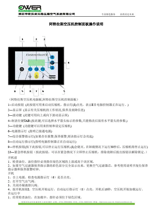
阿特拉斯空压机控制面板操作说明(阿特拉斯空压机电脑板,阿特拉斯空压机控制面板)1--启动按钮(此按钮可用来启动压缩机。
指示灯(8)点亮,表示EⅡ电脑控制器正在运行。
)2—显示屏(显示有关压缩机的工作状况,保养及故障信息)3—滚动键(此键可用向上或向下滚动显示屏)4--制表位键TAB (按此键,可以选择水平箭头标示的参数,只能修改后面有水平箭头的参数.)5—功能键(功能键可以用来控制和设定压缩机)6--电源指示灯(指明已接通电源)7—综合报警指示灯(如果存在报警,保养报警,则该指示灯会亮起)8—自动运行指示灯(指明电脑控制器正在自动运行)9---停机按钮(按下此按钮,可以停止运行压缩机.(8)会熄灭。
在卸载情况下运行30秒后,压缩机将停止运行) S3—紧急停机按钮(按此按钮,可以在紧急情况下立即停止压缩机,排除故障后拔出按钮以解除锁定。
)开机前1、检查油位。
油位指针必须指在绿色区域的上部或高于该区域。
2、如果空气过滤器保养指示器的彩色部分完全显示出来,更换空气过滤器芯,参考使用说明书复位保养指示器和保养报警时钟。
开机1、合上电源。
检查电源指示灯(6)是否点亮。
2、打开空气出气阀。
3、关闭冷凝液排污阀。
4、按开机按钮I。
空压机开始运行,自动运行指示灯(8)点亮,开机后10秒,空压机开始加载运行。
在运行中1、经常检查油位,在加载中,指针必须位于绿色区域。
2、如果指示灯(8)点亮,电脑控制器正自动控制压缩机的加载,卸载,停机和重新启动。
3、经常检查显示屏(2):空压机的运行状态通过图标显示在显示屏上。
4、如果报警指示灯(7)点亮或闪烁,请排除故障,参考使用说明书。
如果需保养,停机并执行保养措施,参考使用说明书。
5、停机1、按停机按钮O。
指示灯(8)熄灭。
空压机大约卸载运行30秒后停机。
2、在紧急情况下停机,按控制面板旁的红色紧急停机按钮,报警指示灯(7)闪烁。
在重新开机前拨出按钮并按重新设置键解除锁定。
破碎锤培训资料-文档资料

破碎锤打击力量不够,可能是液压系统故障、进气管路漏气等原因导致的。
动力不足
动作不稳定
噪音过大
破碎锤打击过程中出现跳动、撞击等现象,可能是活塞运动不规律、液压油不干净等原因引起的。
破碎锤工作时产生的噪音过大,可能是由于振动筛松动、破碎锤内部零件损坏等原因导致的。
03
破碎锤的常见故障
破碎锤的操作注意事项
操作破碎锤时必须佩戴安全帽、防护眼镜等个人防护用品,确保自身安全。
注意安全
避免过度破碎
禁止空击
注意现场环境
操作破碎锤时要注意避免过度破碎,以免造成设备损坏或现场危险。
操作破碎锤时禁止进行空击,以免对设备造成不必要的损害。
操作破碎锤时要注意周围环境,避免对人员和设备造成伤害。
04
2023
《破碎锤培训资料-文档资料》
目录
contents
破碎锤简介破碎锤的结构组成及工作原理破碎锤的操作与维护破碎锤的常见故障及排除方法破碎锤的安全使用规范破碎锤的发展趋势及未来展望
01
破碎锤简介
破碎锤是一种挖掘机属具,用于对物料、钢筋等进行破碎作业。
破碎锤由钎杆、锤头、活塞、弹簧等组成,通过冲击作用将目标破碎。
沙尘和低温环境
在高温和高湿度环境下使用破碎锤时,应特别注意设备的冷却和防锈措施,避免设备故障和缩短使用寿命。
高温和高湿度环境
在腐蚀性环境下使用破碎锤时,应特别注意设备的防腐措施,避免设备腐蚀和损伤。
腐蚀性环境
破碎锤在使用过程中必须遵守国家和企业制定的相关使用规定,包括安全操作规程、维护保养制度等。
目前,全球破碎锤市场规模已超过100亿美元。
高效化
发展更高效的破碎锤技术,提高设备的打击效率和寿命。
破碎锤培训资料文档资料

操作破碎锤需要专业的技能和知识,操 作员必须经过培训并熟悉操作规程。
控制力度和方向
根据需要破碎的物料类型和硬度,控 制破碎锤的力度和方向,避免过度冲
击和反弹。
操作过程中保持警觉
时刻注意周围环境,避免与人员或物 体接触,特别是对于飞溅的碎片和石 块。
避免长时间连续操作
长时间连续操作可能导致疲劳和安全 隐患,应合理安排工作和休息时间。
检查液压系统
确保破碎锤的外观没有破损或裂纹,特别 是对于关键部位如锤头和柄部。
确认液压系统的密封性和压力值是否正常 ,以及液压油是否清洁。
检查电气系统
检查工作环境
检查电缆和插头是否破损或老化,以及电 气设备是否正常工作。
确保工作区域没有障碍物和安全隐患,并 准备好所需的辅助工具。
操作过程中的安全注意事项
密封件损坏
密封件损坏也是破碎锤常 见的故障之一,应更换新 的密封件。
06
破碎锤的操作技巧与经验分享
高效破碎技巧
了解岩石和破碎物的性质 不同的岩石和破碎物有不同的硬 度、脆性和韧性。了解这些特性 有助于选择合适的破碎方法。
调整打击力度 根据岩石和破碎物的硬度,调整 打击力度,以确保破碎效率高且 不损坏设备。
应对锤头松动或脱落
当锤头松动或脱落时,应立即停止操作并采取相应的措施,如重 新紧固锤头或更换锤头等。
THANKS
感谢观看
05
破碎锤的维护与保养
日常维护与保养
保持设备清洁
01
经常清理设备表面的灰尘和污垢,避免杂质进入破碎锤内部。
检查油位和润滑情况
02
每天工作前检查破碎锤的油位和润滑情况,确保设备正常运转
。
阿特拉斯空压机说明书
4.2 控制面板...........................................................................75
4.3 所用图标...........................................................................76
2
概述.......................................................................10
2.1 简介...............................................................................10 2.2 气流...............................................................................14 2.3 润滑油系统.........................................................................17 2.4 冷却系统...........................................................................18 2.5 冷凝水系统(在 PACK 机组上为可选件)...............................................19 2.6 调节系统...........................................................................21 2.7 电气系统...........................................................................22 2.8 电气原理图.........................................................................23 2.9 空气干燥机..................................30
阿特拉斯 井下无轨设备 铲运机 ST1030 操作手册

阿 特 拉 斯 ·科 普 柯 凿 岩 公 司 瑞典厄勒布鲁 SE-70191
2
目录 第 1 章:安全................................................................................................................................................. 8 参考................................................................................................................................................................. 8
阿特拉斯·科普柯铲运机
ST1030 操作手册
PM 编号 9852 1826 01g 2011-09
1
安全说明 • 启动前,请仔细阅读所有说明。 • 对于带有此类标志的信息,须特别注意。 • 仅允许使用阿特拉斯·科普柯原装部件。
1250特拉斯·科普柯凿岩公司版权所有 2011 本说明中所使用的所有产品名称为阿特拉斯·科普柯的商标,归阿特拉斯·科普柯所有。严禁未经许可 而对说明的全部或任何部分内容进行使用或复制。插图和图片中可显示设备所使用的辅助装置。我 们对提供的规范书和其它详细信息不承担责任。规范书和设备如有变更,恕不另行通知。详细信息 请向阿特拉斯·科普柯客服中心咨询。
第 2 章:车辆概况......................................................................................................................................... 9 车辆零件......................................................................................................................................................... 9 主机机架和电源机架..................................................................................................................................... 9 技术资料....................................................................................................................................................... 11 尺寸............................................................................................................................................................... 11 重量............................................................................................................................................................... 11 速度............................................................................................................................................................... 11 其它............................................................................................................................................................... 11 车辆描述....................................................................................................................................................... 12 车辆识别信息............................................................................................................................................... 12 车辆铭牌....................................................................................................................................................... 12
阿特拉斯HB2000,2200液压锤使用维修
阿特拉斯液压锤原理及维修要点芜湖海螺殷亮子一、液压破碎锤的历史1963年,德国克虏伯公司第一个申请了液压震动设备专利,3年后的1966年,克虏伯公司生产了世界上第一台液压破碎锤HM400,并且在汉诺威展览会上首次亮相,2002年,克努伯公司被阿特拉斯公司收购,业内人士一致认为,阿特拉斯是液压破碎锤市场的第一品牌,通过长期的使用,其产品质量较好,液压系统冲击小,效率高,故障率低。
目前集团共有56台破碎锤(截止2013年10月份),主要负责大块的破碎作业,由于效率高,直接取代了以前的手风钻穿孔爆破,大大降低了爆破风险,降低了成本。
但是由于各驾驶员的操作技能参差不齐,维修及维护保养不得当,也导致设备出现了各种问题,芜湖海螺矿山共有两台破碎锤,在使用过程中也出现过各种问题,通过不断地学习、摸索,目前两台液力锤使用均良好,故障率很低。
现将部分液压破碎锤的知识进行归纳,并对部分经验进行共享。
二、液压破碎锤的原理HB2000和HB2200内部结构相同,工作原理没有任何差别,下面以HB2000进行介绍。
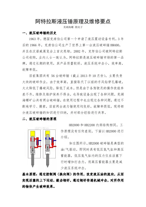
如左图所示,HB2000破碎锤是典型的油/气驱动,即同时具有低压氮气缸和高压蓄能器,低压氮气缸内的压力仅在活塞下行时增加打击力,而高压蓄能器主要是减少液压系统冲击。
基本原理:通过控制阀(换向阀)的作用,改变液压油的流向,从而实现活塞的上下运动,敲击钢钎,通过钢钎传递机械冲击,对所作用的物体产生破碎效果。
HB2000液压破碎锤主要分为三部分:1、上缸体,储存低压氮气、换向阀、蓄能器。
作用是控制活塞冲击。
2、中缸体(油缸)、包括活塞、油封等,作用是产生冲击力的。
3、下缸体,缸体中固定有钢钎、扁销、横销、内外衬套等,作用是固定、润滑钎杆。
三者通过四根通体螺栓进行连接。
图1图2图三图四1、液压油经高压油管进入1腔和8腔:阀芯被油压压在下止点位置;活塞往上,朝气腔5方向运动,此时4腔经阀芯上的四个圆孔与7腔连通,通过换向阀回油。
2200 Series Roller Conveyor安装、维护与零部件手册说明书
For other service manuals visit our website at:/service_manuals.aspDORNER MFG. CORP .INSIDE THE USA OUTSIDE THE USA P.O. Box 20 • 975 Cottonwood Ave.TEL: 1-800-397-8664TEL: 262-367-7600Hartland, WI 53029-0020 USA FAX: 1-800-369-2440FAX: 262-367-5827851-744 Rev. A2200 Series Roller ConveyorInstallation, Maintenance & Parts ManualDorner Mfg. Corp.2851-744 Rev. A2200 Series Roller ConveyorTable of ContentsIntroduction......................................................................... 2Warnings - General Safety ................................................. 3Product Description............................................................. 4Specifications ...................................................................... 4Models:............................................................................ 42200 Series Roller Conveyor....................................... 4Conveyor Supports:......................................................... 4Maximum Distances:.................................................... 4Specifications:.............................................................. 5Roller Quantity / Load Capacity.................................. 5Installation........................................................................... 6Required Tools................................................................. 6Recommended Installation Sequence.............................. 6Install Support Stands...................................................... 6Connecting Conveyors.. (6)Install End Stop................................................................ 6Preventive Maintenance and Adjustment............................ 7Roller Replacement.......................................................... 7Service Parts......................................................................... 82200 Roller Conveyor...................................................... 8Connecting Hardware....................................................... 9Fixed End Stop............................................................... 10-04 3” (76 mm) Aluminum Side.................................... 11-05 1.5” (38 mm) Aluminum Side................................. 12-09 0.5” (12 mm) Aluminum Side................................. 13-10 0.5” (12 mm) Extruded Plastic Side........................ 14-13 Adjustable Guiding ................................................. 15-14 Tool-Less Adjustable Guiding................................ 16Notes.................................................................................. 17Return Policy. (18)IntroductionUpon receipt of shipment:•Compare shipment with packing slip. Contact factory regarding discrepancies.•Inspect packages for shipping damage. Contact carrier regarding damage.•Accessories may be shipped loose. See accessory instruc-tions for installation.Dorner’s Limited Warranty applies.Dorner has convenient, pre -configured kits of Key Service Parts for all conveyor products. These time saving kits are easy to order, designed for fast installation, and guarantee you will have what you need when you need it. Key Parts and Kits are marked in the Service Parts section of this manual with the Performance Parts Kits logo .Dorner reserves the right to make changes at any time without notice or obligation.851-744 Rev. A3Dorner Mfg. Corp.2200 Series Roller ConveyorWarnings - General SafetyA WARNINGThe safety alert symbol, black triangle with white exclamation, is used to alert you to potential personal injury hazards.Climbing, sitting, walking or riding onconveyor will cause severe injury. KEEP OFF CONVEYORS.DO NOT OPERATE CONVEYORS IN AN EXPLOSIVE ENVIRONMENT.WARNINGExposed moving parts can cause severe injury. LOCK OUT POWER before removing guards or performing maintenance.WARNINGDorner cannot control the physicalinstallation and application of conveyors. Taking protective measures is the responsibility of the user.When conveyors are used in conjunction with other equipment or as part of a multiple conveyor system, CHECK FOR POTENTIAL PINCH POINTS and other mechanical hazards before system start-up.WARNINGLoosening stand height or angle adjustment screws may cause conveyor sections to drop down, causing severe injury.SUPPORT CONVEYOR SECTIONS PRIOR TO LOOSENING STAND HEIGHT OR ANGLE ADJUSTMENT SCREWS.A A ADorner Mfg. Corp.4851-744 Rev. A2200 Series Roller ConveyorProduct DescriptionRefer to Figure 1 for typical components.Figure 1SpecificationsModels:2200 Series Roller ConveyorConveyor Supports:Maximum Distances:1 = 18” (457 mm)2 = 6 ft (1829 mm)***3 = 18” (457 mm)*** For conveyors longer than 12 ft (3658 mm), install support at joint.Figure 21Conveyor2Profiles (3” Aluminum Side Shown)3End Stop 4Stands4312123851-744 Rev. A5Dorner Mfg. Corp.2200 Series Roller ConveyorSpecificationsSpecifications:Roller Quantity / Load CapacityConveyor Width Reference (WW) 06121824Conveyor Belt Width 6” (152 mm)12” (304 mm)18” (457 mm)24” (609 mm)Conveyor Roller Width (inch)5” (127 mm)11” (279 mm)17” (431 mm)23” (584 mm)Conveyor Length Reference (LLLL)02000050 increments up to 1200Conveyor Length (Feet) 2 ft0.50 feet increments up to 12 ftRoller Center Reference (SS)12 2436Roller Centers (inch)1.2” (30 mm)2.4” (60 mm)3.6” (91 mm)NOTEIt is recommended that 3 rollers be in contact with the part at all times.Roller Centers1.2” (30 mm)2.4” (60 mm)3.6” (91 mm)Length (ft)# of RollersLoad Capacity(lbs/ft)# of RollersLoad Capacity(lbs/ft)# of RollersLoad Capacity(lbs/ft)2208011508403308016501240440802150164055080265020406608031502440770803650284088080415032409908046503640101008051504040111108056504440121208061504840Dorner Mfg. Corp.6851-744 Rev. A2200 Series Roller ConveyorInstallationRequired Tools•Hex-key wrenches:4 mm, 5 mmRecommended Installation Sequence•Install support stands•Connecting Conveyors (if required)•Install end stop (if required)Install Support Stands1.Insert mounting nuts (Figure 3,item 1) into the bottom t-slots on the conveyor (Figure 3,item 2).Figure 32.Attach stands to the bottom of the conveyor frame using four washers (Figure 3,item 3) and screws (Figure 3,item 4) for each stand.Connecting Conveyors3.Insert t-bars (Figure 4,item 1) into conveyor t-slots (Figure 4,item 2) on each side of conveyor.Figure 44.Attach clamp plate (Figure 4,item 3) with four screws (Figure 4,item 4) on each side of conveyor.Install End Stop1.Attach the flat side of the end stop (Figure 5,item 1) to the conveyor with two screws (Figure 5,item 2).Figure 54132NOTESupport stand is required at frame connection.123412851-744 Rev. A7Dorner Mfg. Corp.2200 Series Roller ConveyorPreventive Maintenance and AdjustmentRoller Replacement1.Compress end (Figure 6,item 1) of roller and remove male hex end (Figure 6,item 2) from the conveyor female hex end (Figure 6,item 3).Figure 6321Dorner Mfg. Corp.8851-744 Rev. A2200 Series Roller ConveyorService Parts2200 Series Roller ConveyorNOTEFor replacement parts other than those shown in this section, contact an authorized Dorner Service Centeror the factory. Key Service Parts and Kits are identified by the Performance Parts Kits logo . Dorner recommends keeping these parts on hand.2ItemPart Number Description1202646-LLLLL Side Rail 2202664-WW Roller3202665-WW Crossmember4920620M Socket Head Screw, M6-1.00 x 20 mm 5990601M Hex Nut 6605279PWasherLLLLL = Part length in inches with 2 decimal places Example: Part Length = 35.25" LLLLL = 03525WW = Conveyor width reference: 06, 12, 18, 242200 Series Roller Conveyor851-744 Rev. A9Dorner Mfg. Corp.Dorner Mfg. Corp.10851-744 Rev. A2200 Series Roller ConveyorService PartsFixed End StopItem Part N umber Description1202667-WW End Stop2960498MHex Head Cap Screw, M4-.70 x 12 mmWW = Conveyor width reference: 06, 12, 18, 242200 Series Roller Conveyor Service Parts-04 3” (76 mm) Aluminum SideItem PartN umber Description1280404-LLLLL3" (76 mm) Guide Rail2202669Guide Clip - Roller Conveyor3639971MK10Single Drop-In T ee Bar (x10)4920694M Socket Head Screw, M6-1.00 x 20 mmLLLLL = Part length in inches with 2 decimal placesExample: Part Length = 35.25" LLLLL = 03525851-744 Rev. A11Dorner Mfg. Corp.Dorner Mfg. Corp.12851-744 Rev. A 2200 Series Roller ConveyorService Parts-05 1.5” (38 mm) Aluminum SideItem Part N umberDescription 1280504-LLLLL 1.5" (38 mm) Guide Rail 2202669Guide Clip - Roller Conveyor 3639971MK10Single Drop-In T ee Bar (x10)4920694M Socket Head Screw, M6-1.00 x 20 mmLLLLL = Part length in inches with 2 decimal placesExample: Part Length = 35.25" LLLLL = 035252200 Series Roller Conveyor Service Parts-09 0.5” (12 mm) Aluminum SideItem PartN umber Description1280904-LLLLL0.5" (12 mm) Guide Rail2202669Guide Clip - Roller Conveyor3639971MK10Single Drop-In T ee Bar (x10)4920694M Socket Head Screw, M6-1.00 x 20 mmLLLLL = Part length in inches with 2 decimal placesExample: Part Length = 35.25" LLLLL = 03525851-744 Rev. A13Dorner Mfg. Corp.Dorner Mfg. Corp.14851-744 Rev. A 2200 Series Roller ConveyorService Parts-10 0.5” (12 mm) Extruded Plastic SideItem Part N umberDescription 1281004-LLLLL 0.5" (12 mm) Guide Rail 2202669Guide Clip - Roller Conveyor 3639971MK10Single Drop-In T ee Bar (x10)4920694M Socket Head Screw, M6-1.00 x 20 mm 5200054P Snap-On Guide (per foot)LLLLL = Part length in inches with 2 decimal placesExample: Part Length = 35.25" LLLLL = 035252200 Series Roller Conveyor Service Parts-13 Adjustable GuidingItem PartN umber Description1460063-LLLLL Aluminum Profile Guide2200830M Drop-In Tee Bar3202004M Mounting Bracket4202027M Guide Mounting Shaft Vertical5202028M Guide Mounting Shaft Horizontal6674175MP Square Nut7807-652Cross Block8807-948Vinyl Shaft Cap9614068P-LLLLL Extruded Guide10920612M Socket Head Screw M6-1.00 x 12mm11920616M Socket Head Screw M6-1.00 x 16mmLLLLL = Part length in inches with 2 decimal placesExample: Part Length = 35.25" LLLLL = 03525851-744 Rev. A15Dorner Mfg. Corp.Dorner Mfg. Corp.16851-744 Rev. A 2200 Series Roller ConveyorService Parts-14 Tool-Less Adjustable GuidingItem Part N umberDescription 1460063-LLLLL Aluminum Profile Guide 2200830M Drop-In Tee Bar 3202004M Mounting Bracket 4202027M Guide Mounting Shaft Vertical 5202028M Guide Mounting Shaft Horizontal 6674175MP Square Nut 7807-1470Cross Block 8807-948Vinyl Shaft Cap 9614068P-LLLLL Extruded Guide 10920612M Socket Head Screw M6-1.00 x 12mm 11920616M Socket Head Screw M6-1.00 x 16mmLLLLL = Part length in inches with 2 decimal placesExample: Part Length = 35.25" LLLLL = 03525Notes2200 Series Roller Conveyor851-744 Rev. A17Dorner Mfg. Corp.851-744 Rev. A Printed in U.S.A.Dorner Mfg. Corp. reserves the right to changeor discontinue products without notice. All products and services are covered in accordance with our standard warranty. All rights reserved. © Dorner Mfg. Corp. 2013DORNER MFG. CORP .975 Cottonwood Ave., PO Box 20 Hartland, WI 53029-0020 USA TEL 1-800-397-8664 (USA)FAX 1-800-369-2440 (USA)Internet: Outside the USA:TEL 1-262-367-7600FAX 1-262-367-5827Return PolicyReturns must have prior written factory authorization or they will not be accepted. Items that are returned to Dorner without authorization will not be credited nor returned to the original sender. When calling for authorization, please have the following information ready for the Dorner factory representative or your local distributor:1.Name and address of customer.2.Dorner part number(s) of item(s) being returned.3.Reason for return.4.Customer's original order number used when ordering the item(s).5.Dorner or distributor invoice number (if available, part serial number).A representative will discuss action to be taken on the returned items and provide a Returned Goods Authorization (RMA) number for reference. RMA will automatically close 30 days after being issued. T o get credit, items must be new and undamaged. There will be a return charge on all items returned for credit, where Dorner was not at fault. It is the customer’s responsibility to prevent damage during return shipping. Damaged or modified items will not be accepted. The customer is responsible for return freight.Returns will not be accep ted after 60 days from original invoice date. The return charge covers inspection, cleaning,disassembly, disposal and reissuing of components to inventory. If a replacement is needed prior to evaluation of returned item, a purchase order must be issued. Credit (if any) is issued only after return and evaluation is complete.Dorner has representatives throughout the world. Contact Dorner for the name of your local representative. Our Customer Service Team will gladly help with your questions on Dorner products.For a copy of Dorner's Warranty, contact factory, distributor, service center or visit our website at .For replacement parts, contact an authorized Dorner Service Center or the factory.Product TypeStandard Products Engineered to order parts Product Line Conveyors Gearmotors & Mounting Packages Support Stands Accessories Spare Parts (non-belt)Spare Belts - Standard Flat Fabric Spare Belts - Cleated & Specialty FabricSpare Belts - Plastic Chain All equipment and parts 110030% return fee for all products except:50% return fee for conveyors with modular belt,cleated belt or specialty belts non-returnable case-by-case22002200 Modular Belt2200 Precision Move23002300 Modular Belt32003200 LPZ3200 Precision Move4100520053006200Controls7200 / 730050% return fee for all products 7350non-returnable 736074007600。
破碎锤
1、通过挖掘机电脑板输入来调整流量
20吨级挖机破碎锤不超过180L/min,除采用B模式外, 对应的发动机转速不应超过1700rpm。
2、机械式调整
帽
弹簧
调整垫
活塞
机械式控制是通过在活塞和弹簧之间加一个 一定厚度的调整垫限制阀杆的移动极限位置,从
而达到调整流量的目的。
3、破碎锤自身部位调整
某些破碎锤用来调节打击频率 的设备安装在油缸的右侧.
侧板螺栓
钎杆
二、工作原理
回程运动
液压油经 高压油管进入1腔 和8腔:阀芯被油 压压在下止点位置; 活塞往上,朝气腔 5方向运动,此时4 腔经阀芯上的四个 圆孔与7腔连通, 通过换向阀回油。
活塞运动换向
当活塞 运动至图示位置 时,高压油经2腔 进入6腔,此时换 向阀的6腔和8腔 均充满等压的高 压油。由于轴肩 面积的不同,阀 芯上移。 之后,活塞 撞击钎杆,恰在此时 活塞中间部分到达2 腔,致使6腔通过2腔、 腔泄掉高压油,由于 8腔一直通高压,所 以阀芯下移,圆孔重 新与7腔连通,完成 一个循环。
破碎器的主要故障四
打击力太低
1.后缸体氮气压力过低。 2.液压油不足。 3.溢流阀压力设定过低。
破碎器的主要故障五
管路过度震动
1.管路没夹好。 2.高压氮气低。 3.皮碗破损。
步骤 4
1.在活塞向下运动撞击钎 杆之前, 活塞切断了和阀 体的所有连接油路. 所以 阀体转换室中的压力降低 为低压.
2.请时刻记住, 阀体和高 压的连接部分始终是高压 状态, 所以阀体向下运动. 3.这个过程发生在一瞬间.
4.与阀体开始向下运动同 时.
三、常见挖机的安装图纸解析
大宇220—V
破碎器的主要故障二
破碎锤培训课件
其他故障及排除方法
电源故障
电源故障会导致破碎锤无法正常启动。排除方法:检查电源线的连接情况,保 证电源正常供应。
控制箱故障
控制箱故障会导致破碎锤无法正常控制。排除方法:检查控制箱的线路和元件 ,及时维修或更换损坏的元件。
05
破碎锤的应用场景和案例分析
破碎锤在建筑行业的应用
01
02
03
拆除旧建筑
停止使用
当需要停止使用破碎锤时,将操纵杆向后拉 ,使活塞收回,破碎锤停止工作。
打击物料
将破碎锤对准物料,调整打击力度和频率, 进行打击。
注意安全
操作破碎锤时应注意周围环境的安全,避免 对人员和物品造成伤害。
维护和保养方法
定期更换液压油和润滑油
根据使用情况定期更换液压油和润滑油,以保证破碎锤的正常运 行。
02
破碎锤的正确使用和维护
使用前的准备工作
1 2
检查液压油、润滑油和冷却水
确保液压油、润滑油和冷却水充足,以保障破碎 锤的正常运行。
检查紧固件
检查破碎锤的紧固件是否松动,如发现松动应及 时拧紧。
3
检查活塞和钎杆
检查活塞和钎杆是否有磨损或变形,如有问题应 及时更换。
操作步骤和注意事项
启动破碎锤
首先启动液压挖掘机,将破碎锤操纵杆向前 推,将破碎锤的活塞推出。
破碎锤培训课件
汇报人: 日期:
目 录
• 破碎锤概述 • 破碎锤的正确使用和维护 • 破碎锤的安全使用规范 • 破碎锤的常见故障及排除方法 • 破碎锤的应用场景和案例分析 • 破碎锤的发展趋势和未来展望
01
破碎锤概述
破碎锤的定义
破碎锤是一种用于破拆混凝土、岩石等硬物的液压设备,也 称为液压破碎镐或液压破碎锤。
液压破碎锤(ZT100)制造工艺及液压控制系统设计说明书
摘要液压破碎锤是工程机械的辅助机械,我国整个社会工业化进程尚未完成,大量的铁路、公路、水利基本建设正在和将要进行。
未来工程方面对各类现代化机械设备的需求将会越来越大,给液压破碎锤等提供了大量的市场机会。
因此要求对液压破碎锤性能上进行改进,提升产品的品质,能够提高工作效率,使其更有效的应用于工程建设。
本文分析了当今液压破碎锤的国内外现状及未来发展趋势,描述了液压破碎锤的研究现状和设计理论。
进行配套零件的设计及其主要零件制造工艺设计,其中上缸体和下缸体是破碎锤产品制造企业生产的核心零件。
本次设计通过查询关于破碎锤技术相关资料,了解破碎锤机械产品的概况、结构和使用性能,掌握配套零部件的技术和性能要求。
结合所学的机械制造专业相关理论和实践知识,分别进行配套零部件二维、三维绘制和装配;制定主要零件上缸体、下缸体的机械制造工艺规程;通过分析破碎锤的动作过程和液压控制要求,设计液压控制系统。
关键词:液压破碎锤;上缸体;下缸体;液压控制系统;制造工艺规程;AbstractConstruction machinery hydraulic breaker is the auxiliary machinery, the process of industrialization of the whole society has not been completed, a large number of railway, highway, water conservancy construction is and will be held. Thus requiring the performance of the hydraulic breaker to improve, enhance product quality, to improve efficiency, make it more effective used in construction.This paper analyzes the current status of hydraulic breaking hammer and future development trends at home and abroad, describes the research hydraulic breaker status and design theory. The supporting parts of the design and manufacturing process design the main part of which is on the cylinder block and cylinder under the hammer the core of manufacturing production parts. The design by understanding the profile of breaking hammer machinery, structure and performance, to master the technology necessary parts and performance requirements. supporting parts respectively two and three dimensional rendering and assembly; by analyzing the broken hammer action processes and hydraulic control requirements, design of hydraulic control system.Keywords: hydraulic breaker; on the block; under the cylinder; hydraulic control system; manufacturing process planning目录摘要 (I)Abstract (II)第1章绪论 (1)1.1 液压破碎锤及其功能应用 (1)1.1.1 液压破碎锤的功能特点 (1)1.1.2 液压破碎锤的应用及举例 (2)1.2 液压破碎锤国内外发展状况 (2)1.2.1 国外现状 (2)1.2.2 国内现状 (2)1.2.3 国内外液压破碎锤的差距 (3)第2章配套零部件设计与分析 (4)2.1 主要配套零部件设计 (4)2.1.1 上缸体 (4)2.1.2 下缸体 (4)2.1.3 夹板安装方式的选择............................... . (6)2.1.4 液压破碎锤组装造型................................. .. (7)2.2 主要配合尺寸的计算........................................ .. (7)2.1.1 钎杆与扁销之间配合间隙校核 (7)2.2.2 钎杆与上导向套之间配合间隙校核 (8)2.2.3 钎杆与下导向套之间配合间隙校核 (9)第3章配套零部件制造工艺设计 (10)3.1 上缸体制造工艺设计 (10)3.1.1 零件分析 (10)3.1.2 机械加工工艺规程设计 (11)3.1.3 制定机加工工艺路线 (12)3.1.4 确定机械加工切削用量及基本工时 (14)3.2 下缸体制造工艺设计 (22)3.2.1 零件分析 (22)3.2.2 机械加工工艺规程设计 (23)3.2.3 制定机加工工艺路线 (24)3.2.4 下缸体制造工艺总过程 (25)第4章液压电气控制系统设计 (25)4.1 液压破碎锤动作要求 (26)4.2 液压控制系统图设计 (26)4.2.1 动作分析 (26)4.2.2 液压控制系统图 (26)4.3液压控制系统工作原理 (28)参考文献 (30)结束语 (31)致谢 (32)附录 (33)第1章绪论本课题说明了对韩国破碎锤机芯(中缸体)为核心,进行配套零件的设计及其主要零件制造工艺设计,机芯(中缸体)是破碎锤产品制造企业生产的核心零件。