jqk00uzd
JUKI 2000系列的设置调整项目汇总

JUKI 2000系列的设置调整项目汇总新手勿试JUKI2000系列的设置(定)的调整由浅入深分四处,分别是:4。
对编程环境的设置。
3。
对优化条件的设置。
2。
对生产操作选项的设置。
1。
对机器功能的设置。
(当然还有一般说来我们不接触的如对MS 参数的设置,命令按钮设置,语言设置等。
)散落在厚厚的InstructionManual中,为方便使用,综合2050,2060,FX-1R等机型,按从机器上设定时的进入位置,可设置可的项目,具体选配,择要整理如下。
一,对机器功能的设置机器上的设定位置:SETUP(设置)MACHINE SETUP(机器设置)SETTING GROUP(设置各组)机器上的设定位置:PRODUCTION(生产)..PRODUCTION FUNCTION(生产支援)..QUICK SETUP(简易准备)..CONVEYOR(传送)..(只有#3,#4)对机器功能的设置可分十七个项目,分别是1*。
ATC 吸嘴配置:自动设置或键盘输入吸嘴号码;吸嘴种类;吸嘴真空值;吸嘴高度。
2.无吸嘴真空值:自动设置无吸嘴时的真空值;3***.定位销位置(OPTION):用HOD 与OCC照相机示教定位销与从动销坐标;并自动计算校正角。
4***.外形定位的基准位置:用HOD 与OCC照相机示教外形定位的基准位置5.MTC滑梭吸取位置:用HOD 与OCC照相机示教MTC滑梭吸取位置的XY坐标值,用贴片头与吸嘴示教MTC滑梭吸取位置的Z值6.MTS装配位置偏差:用HOD 与OCC照相机示教MTS第一标记与第二标记(装配位置偏差)7。
元件废弃位置:示教或键入不同元件的废弃位置8.IC回收带位置:示教IC回收带位置的X,Y,Z值9.手工操作取回废弃元件时的贴片头等待位置:用HOD 与OCC照相机示教或键入手工操作取回废弃元件时的贴片头等待位置10**.使用单元配置(分ABCD四部分):A:标准使用单元配置:贴片头*与FEEDER浮动传感器FFD。
大众控制单元编码

大众控制单元编码------强烈推荐给大家!!C5 发动机4D0 907 551 AH CODING 号码01 - engine 发动机系统4d0 907 551 ah 2.8l v6/5v motr hs d04coding: 06201 wsc 06335tdc 16825 - evap emission control sys: incorrect flow Re:大众奥迪全车系电脑版本号大家都来贴!!!audi a4 1.808 -空调系统4a0 820 043dcoding 0004000060 Re:大众奥迪全车系电脑版本号大家都来贴!!!宝来汽车电脑版本号01- 发动机:06a 906 032jb 1.6l 5v at ag4 4629coding:00033 wsc:0000002-自动变速箱零件号码01m 927 733 kk 组件ag4 getriebe 01m 4989 coding 号00000 维修站号码0000017-组合仪表(防盗)电脑版本:1j5920806c komb1+wegfahrsp vdo v02coding: 01102 wsc: 0000046-舒适系统零件号码1c0 959 799 组件1m komfortger athlo 0002 coding 号00259 维修站号码000002003-8-15 0:01:11以上为宝来1.8T AT车全车电脑版本号ecu 外观照片01 - 发动机02 - 自动波03 - abs mk6015 - airbag 17 - 仪表/immo 19 - can-bus 网关19 - 网关斯科达法比亚AIRBAG 1J0 909 603vag number index coding=========== ===== =====1j0 909 603 as airbag 167231j0 909 603 at airbag 167242002 Jetta 1.8T 电脑版本号2002 jetta 1.8t金德k81/pc2000 for windows xp 双模式01 --发动机: 06a 906 032 hf 1.8l r4/5vt g 0004coding: 07550 wsc 13622vin:3vwse69m62m112530immo sn:vwz7z0a418528402 -- 自动波09a 927 750 t ag5 getriebe 09a 019303 -- abs: 1c0 907 379 k asr front mk60 0103coding: 0018945 wsc 0002817 -- 仪表/immo : 1j5 920 926 ax kombi+wegfahrsp vdo v11coding: 07204 wsc 225853vwse69m62m112530 vwz7z0a418528419 -- 网关6n0 909 901 gateway kcan 0001coding: 00006 wsc 2258546 -- 中控与舒适系统1c0 959 799 c 1h komfortger醫hlo 0003coding: 00257 wsc 0002856 -- 收放机3b7 035 180 radio np2 0055coding: 00031 wsc 00028Re:大众奥迪全车系电脑版本号大家都来贴!!!发表: 2003-10-07 13:57:24 人气:3 楼主美规原装奥迪a6.2.8l 手动自动两用波箱电脑型号发动机电脑:4d0907551ah 2.8l v6/5v motrat d02coding:06252波箱电脑:4b09271156g ag501v 2.8l5v usa 8509coding:00001abs电脑:8e0614111m abs/eds5.3 ouattro d31coding:06169仪表电脑:4b0919930rx c5-kombiinstr vdo d15coding:07262空调电脑:4b0820043g a6-klimavoll automat:d61coding:00160中央控制门锁:4b0962258c centrallock/alarm d30coding:15885Re:大众奥迪全车系电脑版本号大家都来贴!!!宝来1.6l a/t发动机的coding:00033 abs:0001025 a/t:00000 仪表:01102 音响:00001 舒适性系统:00259 捷达:1.6l a/t发动机的coding:04030 a/t:03604 srs:00065 防盗:09600 捷达都市先锋发动机:04003 a/t:00000 abs:03604Re:大众奥迪全车系电脑版本号大家都来贴!!!一汽新a6address 01protocol: kw1281controller: 3b0 907 551 ckcomponent: 2.8l v6/5v 0002coding: 08502shop #: wsc 00000address 03protocol: kw1281controller: 3b0 614 111component: abs/asr 5.3 front d00coding: 00032shop #: wsc 00000skipping address 15-airbagsaddress 17protocol: kw1281controller: 4c0 920 930 bcomponent: c5-kombiinstr. vdo d12coding: 00162shop #: wsc 000002003-11-12 10:38:052001.5 VW Passat 1.8T w/ engine code AWM.4b0-906-018-cl using a 2001.5 vw passat 1.8t w/ engine code awm.audi dtc table - general4b0-906-018-cl数据流diagnostic trouble code (dtc) table vw technical library【01-发动机】4b0 906 018 cl 1.8l r4/5vt g 0001coding: 16551 wsc 00008wvwpd63b61p269969 vwz7z0a35518632 faults found:17524 - oxygen (lambda) sensor heating: b1 s1: open circuitp1116 - 35-00 - -18034 - powertrain data bus: missing message from tcup1626 - 35-10 - - - intermittentreadiness: 0110 1101【02 - 自动波】4b0 927 156 da ag5 01v 1.8l5vt rdw 1313coding: 00013 wsc 000082 faults found:18158 - supply voltage too lowp1750 - 35-10 - - - intermittent18249 - engine control module / transmission control module incompatible p1841 - 35-00 - -【03 -abs 】3b0 614 111 abs/asr 5.3 front d00coding: 00021 wsc 000281 faults found:18257 - please check dtc memory of transmission controllerp1849 - 35-00 - -skipping address 15-airbags【17 -仪表&immo】3b0 920 925 b kombi+wegfahrsp vdo v13coding: 07235 wsc 00008wvwpd63b61p269969 vwz7z0a35518633 faults found:00779 - outside air temp sensor (g17)30-10 - open or short to b+ - intermittent01316 - abs control module49-10 - no communications - intermittent01315 - transmission control module49-10 - no communications - intermittent【25 - immobilizer】controller: bitte adress e 17 eingeben 请转到地址17-仪表与防盗no faults foundor dtcs not supported by controlleror a communication error ocurred【46 - 中控与舒适系统】1c0 959 799 c 08 komfortger醫hlo 0001 coding: 00257 wsc 00008AUDI C5 A6 2.8L 全车电脑版本号奥迪a6 2.8l vin:lfvba24bx2300155201)3b0 907 551 bf 2.8l v6/5v g01 001coding:04552 wsc:0000002)4b0 927 156 aj ag5 01v 2.8l5v usa 3132coding:00004 wsc:0000003)3b0 614 111 abs/asr 5.3 front d00coding:00031 wsc:0000015)4b0 959 655 g airbag fronttseite 2001coding:00004 wsc:0000035)4b0 962 258 j central lock/alarm d35coding:06731 wsc:0000045?)4b0 907 357 ledchtwetteregler d004coding:00005 wsc:0000036)4b0 959 608 sitzmamnory r1 f 000coding:00000 wsc:0000056)4c0 035 186 radio d02coding:0020766)4b0 919 283 parkingsystem a6 row d18coding:0110617)4c0 920 930 a ch-komriinstr vdo d12coding:00162-------- --------08)4b0 820 043 af a6-klimavnllautomat d65coding:00160奥迪a6 2.4l vin:vba24b013014521 ?15??01)3b0 907 552 ad 2.4l v6/5v g 0000coding:04552------------ -------------02)4b0 927 156 al ag5 01v 2.4l5v rhw 2526 coding:0001303)3b0 614 111 abs/asr 5.3 front d00coding:0003115)4b0 959 655g airbag fronttseite 2000coding:0000435)4b0 962 258 e zentralverrieg.dwa d34coding:0468345)4b0 951 178 a (?unnenmumueberw) d04 coding: 0000136)4b0 959 760 a sitzmemnry d0556)4c0 035 186 radio d02coding:0020766)4b0 919 283 parkingsystem a6 row d18 coding:0010617)4c0 920 930 a c5-komhi instr vdo d09coding:00062--------- ---------08)4b0 820 043 af a6-klimavcllautomat d65 ciding:001602003-11-24 22:49:35AUDI C5 A6 1.8L 全车电脑版本号奥迪a6 1.8l vin:vba14b22301545501)4r0 906 018 ca 1.8l r4/5vt 0003 coding:04502--------- -----------03)3b0 614 111 abs/asr 5.3 front d00 coding:0002215)4b0 959 655g airbag frongt+seite 2001 coding:0000435)4b0 962 258j central lock/alarm d35 coding:0000156)4c0 035 186 radiocoding:0020117)4c0 920 900a c5-komri instr vdo d12 coding:00144---------- -----------08)4b0 820 043h a6-klimauollautomat d64 coding:00140宝来1.8L全车电脑版本号宝来1.8l vin:lfvba21j223023928宝来1.8L全车电脑版本号宝来1.8l vin:lfvba21j22302392801)06a 906 032 ld 1.8l r4/5vt 0001 coding:04530-------- ---------02)01m 927 733 ll ag4 getribe 01m 4956 coding:0000003)1c0 907 379k asr pront mk60 0103 coding:002150515)1c0 909 601 2k airbag vw51 0004 coding:1287546)1c0 959 799c 18 komfortger bf hlo 0003 coding:0025956)3bd 035 186 radio 5gd 0001coding:0040317)1j5 920 826a komritwegfahrsp vdo v04 coding:0512208)3b1 907 044c climatronic c 2.0.0 coding:0110019)6n0 909 901 gateway k<->can 0000 coding:00006又一个1.8l vin:vba14b22301545501)06a 906 032 lf 1.8l r4/5vs motr 0001 coding:04530-------- --------02)01m 927 733 kj ag4 getriehe 01m 4952 coding:0000003)1c0 907 379 k asr front mk60 0103 coding:001331315)1c0 909 601 2k airbag vw51 0006 coding:1287536)3r1 959 760 sitzverstellung 0101 coding:000000046)1c0 959 799 c 1h komfortger gt hlw 0003coding:002591c1 959 801a 1c1 959 802a1c0 959 811a 1c0 959 812a56)3bd 035 186 radio 5gd 0001coding:0040317)1jd 920 826 komri+megahrsp vdo v02coding:0510208)3b1 907 044c cljmatronic c2.0.019)6n0 909 901 gateway k<->can 0001coding:000062003-11-24 23:54:57Re:大众奥迪全车系电脑版本号大家都来贴!!!核对:是00004.该车行使里程83117km,故障在地址35:1)01370 035alarm via interior scanning2)00956 009key 2adaption limit exceeded s/p3)01570 029switch-off delag.term-15short circuit to earth是保险丝断了,应该日记没错。
74LVC1G157-Q100 单路2输入复用器商品说明书

74LVC1G157-Q100Single 2-input multiplexerRev. 2 — 8 December 2016Product data sheet1.General descriptionThe 74LVC1G157-Q100 is a single 2-input multiplexer which select data from two datainputs (I0 and I1) under control of a common data select input (S). The state of thecommon data select input determines the particular register from which the data comes.The output (Y) presents the selected data in the true (non-inverted) form.Inputs can be driven from either 3.3V or5V devices. This feature allows the use of thesedevices as translators in mixed 3.3V and5V applications.This device is fully specified for partial power-down applications using I OFF.The I OFF circuitry disables the output, preventing the damaging backflow current throughthe device when it is powered down.Schmitt-trigger action at all inputs makes the circuit highly tolerant to slower input rise andfall times.This product has been qualified to the Automotive Electronics Council (AEC) standardQ100 (Grade 1) and is suitable for use in automotive applications.2.Features and benefits⏹Automotive product qualification in accordance with AEC-Q100 (Grade 1)◆Specified from -40︒C to +85︒C and from -40︒C to +125︒C⏹Wide supply voltage range from 1.65 V to5.5V⏹High noise immunity⏹Complies with JEDEC standard:◆JESD8-7 (1.65 V to1.95V)◆JESD8-5 (2.3 V to2.7V)◆JESD8B/JESD36 (2.7 V to3.6V)⏹±24mA output drive (V CC=3.0V)⏹CMOS low power consumption⏹Latch-up performance exceeds 250mA⏹Direct interface with TTL levels⏹Inputs accept voltages up to 5V⏹ESD protection:◆MIL-STD-883, method 3015 exceeds 2000 V◆HBM JESD22-A114F exceeds 2000V◆MM JESD22-A115-A exceeds 200V (C = 200 pF, R = 0 Ω)⏹Multiple package options3. Ordering informationTable 1.Ordering informationType number PackageTemperature range Name Description Version 74LVC1G157GW-Q100-40︒C to+125︒C SC-88plastic surface-mounted package; 6 leads SOT363 74LVC1G157GV-Q100-40 ︒C to +125 ︒C SC-74plastic surface-mounted package (TSOP6); 6 leads SOT4574. MarkingTable 2.MarkingType number Marking code[1]74LVC1G157GW-Q100YP74LVC1G157GV-Q100YP[1]The pin 1 indicator is located on the lower left corner of the device, below the marking code.5. Functional diagram6. Pinning information6.1Pinning6.2Pin descriptionTable 3.Pin descriptionSymbol Pin DescriptionI11data input from source 1 GND2ground (0V)I03data input from source 0 Y4multiplexer outputV CC5supply voltageS6common data select input7. Functional descriptionTable 4.Function table[1]Inputs OutputS I1I0YL X L LL X H HH L X LH H X H[1]H=HIGH voltage level;L=LOW voltage level;X=don’t care.8. Limiting valuesTable 5.Limiting valuesIn accordance with the Absolute Maximum Rating System (IEC 60134). Voltages are referenced to GND (ground = 0 V). Symbol Parameter Conditions Min Max UnitV CC supply voltage-0.5+6.5VI IK input clamping current V I < 0 V-50-mAV I input voltage[1]-0.5+6.5VI OK output clamping current V O > V CC or V O < 0 V-±50mAV O output voltage Active mode[1][2]-0.5V CC + 0.5VPower-down mode[1][2]-0.5+6.5VI O output current V O = 0 V to V CC-±50mAI CC supply current-100mAI GND ground current-100-mAP tot total power dissipation T amb=-40︒C to+125︒C[3]-250mWT stg storage temperature-65+150︒C[1]The input and output voltage ratings may be exceeded if the input and output current ratings are observed.[2]When V CC=0V (Power-down mode), the output voltage can be 5.5V in normal operation.[3]For SC-88 and SC-74 packages: above 87.5︒C the value of P tot derates linearly with 4.0mW/K.9. Recommended operating conditions10. Static characteristicsTable 6.Recommended operating conditions Symbol Parameter ConditionsMin Typ Max Unit V CC supply voltage 1.65- 5.5V V I input voltage 0- 5.5V V O output voltage Active mode--V CC V V CC = 0 V; Power-down mode -- 5.5V T amb ambient temperature-40-+125︒C ∆t/∆Vinput transition rise and fall rate V CC = 1.65 V to 2.7 V--20ns/V V CC = 2.7 V to 5.5 V --10ns/VTable 7.Static characteristicsAt recommended operating conditions. Voltages are referenced to GND (ground =0V).Symbol Parameter Conditions-40 ︒C to +85 ︒C -40 ︒C to +125 ︒C UnitMin Typ [1]Max Min Max V IHHIGH-level input voltageV CC = 1.65 V to 1.95 V 0.65V CC--0.65V CC-V V CC = 2.3 V to 2.7 V 1.7-- 1.7-V V CC = 2.7 V to 3.6 V 2.0-- 2.0-V V CC = 4.5 V to 5.5 V0.7V CC--0.7V CC-V V ILLOW-level input voltageV CC = 1.65 V to 1.95 V --0.35V CC-0.35V CC VV CC = 2.3 V to 2.7 V --0.7-0.7V V CC = 2.7 V to 3.6 V --0.8-0.8V V CC = 4.5 V to 5.5 V--0.3V CC-0.3V CCV V OHHIGH-level output voltage V I =V IH or V IL I O =-100 μA;V CC =1.65V to 5.5VV CC -0.1--V CC -0.1-V I O =-4mA; V CC = 1.65V 1.2 1.54-0.95-V I O =-8mA; V CC = 2.3V 1.9 2.15- 1.7-V I O =-12mA; V CC = 2.7 V 2.2 2.50- 1.9-V I O =-24mA; V CC = 3.0 V 2.3 2.62- 2.0-V I O =-32mA; V CC = 4.5 V3.84.11- 3.4-V V OLLOW-level output voltage V I =V IH or V IL I O =100μA;V CC =1.65V to 5.5 V--0.10-0.10V I O =4mA;V CC = 1.65V -0.070.45-0.70V I O =8mA;V CC = 2.3V -0.120.30-0.45V I O =12mA;V CC = 2.7 V -0.170.40-0.60V I O =24mA;V CC = 3.0 V -0.330.55-0.80V I O =32mA;V CC = 4.5 V-0.390.55-0.80V[1]All typical values are measured at T amb =25︒C.11. Dynamic characteristics[1]Typical values are measured at T amb =25︒C and V CC = 1.8 V, 2.5 V, 2.7 V, 3.3 V and 5.0 V respectively.[2]t pd is the same as t PLH and t PHL .[3]C PD is used to determine the dynamic power dissipation (P D in μW).P D =C PD ⨯V CC 2⨯f i ⨯N +∑(C L ⨯V CC 2⨯f o )where:f i =input frequency in MHz;f o =output frequency in MHz;C L =output load capacitance in pF;V CC =supply voltage in Volts;N =number of inputs switching;∑(C L ⨯V CC 2⨯f o )=sum of the outputs.I I input leakage currentV I = 5.5 V or GND; V CC =0V to 5.5V-±0.1±1-±1μA I OFF power-off leakage current V CC = 0 V; V I or V O =5.5V -±0.1±2-±2μA I CC supply current V I = 5.5 V or GND; I O = 0 A; V CC =1.65V to 5.5 V -0.14-4μA ∆I CC additional supply currentper pin; V CC = 2.3 V to 5.5 V; V I =V CC -0.6V; I O =0 A -5500-500μA C Iinput capacitanceV CC =3.3V;V I = GND to V CC-2.5---pFTable 7.Static characteristics …continuedAt recommended operating conditions. Voltages are referenced to GND (ground =0V).Symbol Parameter Conditions -40 ︒C to +85 ︒C -40 ︒C to +125 ︒C Unit MinTyp [1]Max Min Max Table 8.Dynamic characteristicsVoltages are referenced to GND (ground =0V); for load circuit see Figure 7.Symbol Parameter Conditions-40 ︒C to +85 ︒C -40 ︒C to +125 ︒C UnitMinTyp [1]Max Min Max t pdpropagation delay I0, I1 to Y; see Figure 6[2]V CC = 1.65 V to 1.95 V 1.5 4.311.0 1.513.0ns V CC = 2.3 V to 2.7 V 1.0 2.9 6.1 1.07.6ns V CC = 2.7 V 1.0 3.1 5.6 1.07.0ns V CC = 3.0 V to 3.6 V 1.0 2.7 5.0 1.0 6.3ns V CC = 4.5 V to 5.5 V 0.52.2 4.00.5 5.0ns S to Y; see Figure 6[2]V CC = 1.65 V to 1.95 V 1.5 4.311.0 1.513.0ns V CC = 2.3 V to 2.7 V 1.0 2.9 6.9 1.08.6ns V CC = 2.7 V 1.0 3.3 5.9 1.07.4ns V CC = 3.0 V to 3.6 V 1.0 2.9 5.0 1.0 6.3ns V CC = 4.5 V to 5.5 V0.52.3 4.00.5 5.0ns C PDpower dissipation capacitanceV I = GND to V CC ; V CC =3.3 V [3]-18---pF12. WaveformsTable 9.Measurement pointsSupply voltage Input Output V CC V M V M1.65V to 1.95V0.5V CC0.5V CC2.3V to 2.7V0.5V CC0.5V CC2.7V 1.5V 1.5V3.0V to 3.6V 1.5V 1.5V4.5V to5.5V0.5V CC0.5V CCTable 10.Test dataSupply voltage Input Load V EXTV CC V I t r=t f C L R L t PLH, t PHL1.65V to 1.95V V CC≤2.0ns30pF1kΩopen2.3V to 2.7V V CC≤2.0ns30pF500Ωopen2.7V 2.7V≤2.5ns50pF500Ωopen3.0V to 3.6V 2.7V≤2.5ns50pF500Ωopen4.5V to5.5V V CC≤2.5ns50pF500Ωopen13. Package outline3ODVWLF VXUIDFH PRXQWHG SDFNDJH OHDGV627Fig 8.Package outline SOT363 (SC-88)3ODVWLF VXUIDFH PRXQWHG SDFNDJH 7623 OHDGV627Fig 9.Package outline SOT457 (SC-74)14. AbbreviationsTable 11.AbbreviationsAcronym DescriptionCMOS Complementary Metal Oxide SemiconductorDUT Device Under TestESD ElectroStatic DischargeHBM Human Body ModelMM Machine ModelMIL MilitaryTTL Transistor-Transistor Logic15. Revision historyTable 12.Revision historyDocument ID Release date Data sheet status Change notice Supersedes74LVC1G157_Q100 v.220161208Product data sheet-74LVC1G157_Q100 v.1 Modifications:•Table7: The maximum limits for leakage current and supply current have changed.74LVC1G157_Q100 v.120130121Product data sheet--16. Legal information16.1 Data sheet status[1]Please consult the most recently issued document before initiating or completing a design.[2]The term ‘short data sheet’ is explained in section “Definitions”.[3]The product status of device(s) described in this document may have changed since this document was published and may differ in case of multiple devices. The latest product statusinformation is available on the Internet at URL .16.2 DefinitionsDraft — The document is a draft version only. The content is still under internal review and subject to formal approval, which may result in modifications or additions. Nexperia does not give anyrepresentations or warranties as to the accuracy or completeness of information included herein and shall have no liability for the consequences of use of such information.Short data sheet — A short data sheet is an extract from a full data sheet with the same product type number(s) and title. A short data sheet is intended for quick reference only and should not be relied upon to contain detailed and full information. For detailed and full information see the relevant full data sheet, which is available on request via the local Nexperia salesoffice. In case of any inconsistency or conflict with the short data sheet, the full data sheet shall prevail.Product specification — The information and data provided in a Product data sheet shall define the specification of the product as agreed between Nexperia and its customer, unless Nexperia andcustomer have explicitly agreed otherwise in writing. In no event however, shall an agreement be valid in which the Nexperia product isdeemed to offer functions and qualities beyond those described in the Product data sheet.16.3 DisclaimersLimited warranty and liability — Information in this document is believed to be accurate and reliable. However, Nexperia does not give any representations or warranties, expressed or implied, as to the accuracy or completeness of such information and shall have no liability for the consequences of use of such information. Nexperia takes noresponsibility for the content in this document if provided by an information source outside of Nexperia.In no event shall Nexperia be liable for any indirect, incidental,punitive, special or consequential damages (including - without limitation - lost profits, lost savings, business interruption, costs related to the removal or replacement of any products or rework charges) whether or not such damages are based on tort (including negligence), warranty, breach of contract or any other legal theory.Notwithstanding any damages that customer might incur for any reason whatsoever, Nexperia’s aggregate and cumulative liability towards customer for the products described herein shall be limited in accordance with the Terms and conditions of commercial sale of Nexperia.Right to make changes — Nexperia reserves the right to makechanges to information published in this document, including without limitation specifications and product descriptions, at any time and without notice. This document supersedes and replaces all information supplied prior to the publication hereof.Suitability for use in automotive applications — This Nexperiaproduct has been qualified for use in automotiveapplications. Unless otherwise agreed in writing, the product is not designed, authorized or warranted to be suitable for use in life support, life-critical or safety-critical systems or equipment, nor in applications where failure or malfunction of a Nexperia product can reasonably be expectedto result in personal injury, death or severe property or environmental damage. Nexperia and its suppliers accept no liability forinclusion and/or use of Nexperia products in such equipment or applications and therefore such inclusion and/or use is at the customer's own risk.Applications — Applications that are described herein for any of these products are for illustrative purposes only. Nexperia makes no representation or warranty that such applications will be suitable for the specified use without further testing or modification.Customers are responsible for the design and operation of their applications and products using Nexperia products, and Nexperiaaccepts no liability for any assistance with applications or customer product design. It is customer’s sole responsibility to determine whether the Nexperia product is suitable and fit for the customer’s applications andproducts planned, as well as for the planned application and use of customer’s third party customer(s). Customers should provide appropriate design and operating safeguards to minimize the risks associated with their applications and products.Nexperia does not accept any liability related to any default,damage, costs or problem which is based on any weakness or default in the customer’s applications or products, or the application or use by customer’s third party customer(s). Customer is responsible for doing all necessary testing for the customer’s applications and products using Nexperia products in order to avoid a default of the applications andthe products or of the application or use by customer’s third partycustomer(s). Nexperia does not accept any liability in this respect.Limiting values — Stress above one or more limiting values (as defined in the Absolute Maximum Ratings System of IEC60134) will cause permanent damage to the device. Limiting values are stress ratings only and (proper) operation of the device at these or any other conditions above those given in the Recommended operating conditions section (if present) or the Characteristics sections of this document is not warranted. Constant or repeated exposure to limiting values will permanently and irreversibly affect the quality and reliability of the device.Terms and conditions of commercial sale — Nexperiaproducts are sold subject to the general terms and conditions of commercial sale, as published at /profile/terms, unless otherwise agreed in a valid written individual agreement. In case an individual agreement is concluded only the terms and conditions of the respective agreement shall apply. Nexperia hereby expressly objects toapplying the customer’s general terms and conditions with regard to the purchase of Nexperia products by customer.Document status[1][2]Product status[3]DefinitionObjective [short] data sheet Development This document contains data from the objective specification for product development. Preliminary [short] data sheet Qualification This document contains data from the preliminary specification.Product [short] data sheet Production This document contains the product specification.No offer to sell or license — Nothing in this document may be interpreted or construed as an offer to sell products that is open for acceptance or the grant, conveyance or implication of any license under any copyrights, patents or other industrial or intellectual property rights.Export control — This document as well as the item(s) described herein may be subject to export control regulations. Export might require a prior authorization from competent authorities.Translations — A non-English (translated) version of a document is for reference only. The English version shall prevail in case of any discrepancy between the translated and English versions.16.4 TrademarksNotice: All referenced brands, product names, service names and trademarks are the property of their respective owners.17. Contact informationFor more information, please visit: For sales office addresses, please send an email to: ***************************18. Contents1 General description. . . . . . . . . . . . . . . . . . . . . . 12 Features and benefits . . . . . . . . . . . . . . . . . . . . 13 Ordering information. . . . . . . . . . . . . . . . . . . . . 24 Marking. . . . . . . . . . . . . . . . . . . . . . . . . . . . . . . . 25 Functional diagram . . . . . . . . . . . . . . . . . . . . . . 26 Pinning information. . . . . . . . . . . . . . . . . . . . . . 36.1 Pinning . . . . . . . . . . . . . . . . . . . . . . . . . . . . . . . 36.2 Pin description . . . . . . . . . . . . . . . . . . . . . . . . . 37 Functional description . . . . . . . . . . . . . . . . . . . 48 Limiting values. . . . . . . . . . . . . . . . . . . . . . . . . . 49 Recommended operating conditions. . . . . . . . 510 Static characteristics. . . . . . . . . . . . . . . . . . . . . 511 Dynamic characteristics . . . . . . . . . . . . . . . . . . 612 Waveforms . . . . . . . . . . . . . . . . . . . . . . . . . . . . . 713 Package outline . . . . . . . . . . . . . . . . . . . . . . . . . 914 Abbreviations. . . . . . . . . . . . . . . . . . . . . . . . . . 1115 Revision history. . . . . . . . . . . . . . . . . . . . . . . . 1116 Legal information. . . . . . . . . . . . . . . . . . . . . . . 1216.1 Data sheet status . . . . . . . . . . . . . . . . . . . . . . 1216.2 Definitions. . . . . . . . . . . . . . . . . . . . . . . . . . . . 1216.3 Disclaimers. . . . . . . . . . . . . . . . . . . . . . . . . . . 1216.4 Trademarks. . . . . . . . . . . . . . . . . . . . . . . . . . . 1317 Contact information. . . . . . . . . . . . . . . . . . . . . 1318 Contents . . . . . . . . . . . . . . . . . . . . . . . . . . . . . . 14© Nexperia B.V. 2017. All rights reserved For more information, please visit: Forsalesofficeaddresses,pleasesendanemailto:*************************** Date of release:Mouser ElectronicsAuthorized DistributorClick to View Pricing, Inventory, Delivery & Lifecycle Information:N experia:74LVC1G157GV-Q100H74LVC1G157GW-Q100H。
40EOZD 33EFOZD型号的Kohler生成器说明书
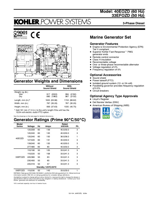
Model:40EOZD (60Hz)33EFOZD (50Hz)Generator FeaturesD Engine is Environmental Protection Agency (EPA)Tier II compliantD Superior Kohler Fast-Response t PMG generator endsD Remote control connector D Class H insulationD Reconnectable voltageD One-or three-phase reconnectable alternator D Voltage regulation of 2%D Frequency regulation of 5%Optional AccessoriesD Sound shieldD Power takeoff (PTO)D Isolated ground system (12-or 24-volt)DParalleling governor provides frequency regulation of 0.5%D Circuit breakersOptional Agency Type ApprovalsD Lloyd’s RegisterD Det Norske Veritas (DNV)D American Bureau of Shipping (ABS)Marine GeneratorSetGenerator Weights and DimensionsWithout Sound ShieldWithSound Shield Weight,kg (lb.)Wet Dry 917(2022)890(1962)994(2192)967(2132)Length,mm (in.)*1625(63.96)1743(68.62)Width,mm (in.)767(30.20)767(30.20)Height,mm (in.)956(37.63)1035(40.75)*Add 181mm (7.14in.)to the unit’s length if the unit has the 12/24-volt electric clutch PTO option.See the drawings on the last page for detailed dimensions.Generator Ratings (Prime 90_C/50_C)Model SeriesVoltage Hz Amps Rated kW/kVA Ph 40EOZD120/2086013940.0/50.03120/2406012040.0/50.03120/2406015036.0/36.01127/2206013140.0/50.03139/2406012040.0/50.03277/480606040.0/50.0333EFOZD110/1905012533.0/41.33110/2205010833.0/41.33220/380506333.0/41.33230/400506033.0/41.33240/416505733.0/41.33Standby 125_C/25_C33EFOZD115/2305014333.0/33.01RATINGS:Ratings per ISO 3046,ISO 8528-1,and Kohler ISO rating guideline 2.14.Obtain technical information bulletin (TIB-101)on ratings guidelines for complete ratings definitions.Availability is subject to change without notice.Kohler Co.reserves the right to change the design or specifications without notice and without any obligation or liability whatsoever.Contact your local Kohler generator set distributor for availability.10%overload capacity one hour in twelve hours.Application DataEngineEngine Specifications60Hz50Hz Type Inline,4-cycle Number of cylinders4Firing order1-3-4-2 Aspiration Natural Displacement,L(cu.in.) 4.5(275)Bore and stroke,mm(in.)106x127(4.19x5.00) Compression ratio17.6:1 Combustion system Direct injection Rated rpm18001500 Maximum power at rated rpm,HP6254 Cylinder block material Cast iron Cylinder head material Cast ironPiston rings2compression/1oil Crankshaft material Forged steel Connecting rod material Forged steel Governor type MechanicalEngine ElectricalEngine Electrical System60Hz50Hz Battery,voltage12-or24-volt spec Battery,charging(12volt)65amp Battery,charging(24volt)40amp Battery,recommendation(minimum,12volt)640CCAStarter motor Gear-reduction typeCoolingCooling System60Hz50Hz Capacity,L(U.S.qt.)(approx.)12(13)Cooling type Heat exchanger Seawater pump type John Deere gear driven Seawater pump suction lift,maximum,m(ft.) 3.0(10.0)Heat rejected to cooling water at ratedkW,wet exhaust,kW(Btu/min.)42(2391)31.5(1793) Engine water pump flow,Lpm(gpm)125(32)116(30) Seawater pump flow,Lpm(gpm)84(22)70(18)FuelFuel System60Hz50Hz Fuel recommendation Diesel fuel specified toEN590or ASTM D975 Fuel shutoff solenoid ElectricFuel injection pump Stanadyne DB4,mechanical Fuel pump priming Manual Maximum recommended fuel lift,m(ft.) 3.0(10.0)LubricationLubricating System60Hz50HzOil pan capacity with filter,L(U.S.qt.)7.5(8)Type PressureOperation RequirementsAir Requirements60Hz50Hz Engine combustion air requirements,m3/min.(cfm) 3.6(127) 2.4(85) Max.air intake restriction,kPa(in.H2O) 6.25(25) 6.25(25) Cooling air required for generator set at50_C(122_F)ambient,m3/min.(cfm)18.3(600)15.2(500) Exhaust flow,m3/min.(cfm)10.4(367)7.0(237) Exhaust temp.,_C(_F)587(1089)565(1049) Max.allowed exhaust backpressure,kPa(in.H2O)7.5(30)7.5(30) Fuel Consumption60Hz50Hz Diesel,Lph(gph)at%load100%12.5(3.3)10.1(2.7)75%9.9(2.6)7.8(2.1)50%7.1(1.9) 5.5(1.5)25% 4.3(1.1) 3.4(0.9)Engine FeaturesD One-side serviceability of fuel system,lubrication system,and aircleanerD Low oil pressure cutoutD High water temperature cutoutD Loss of coolant cutoutD Overcrank cutoutD Belt guardD Optional oil pressure gauge,water temperature gauge,and batteryvoltage gaugeD Disposable oil filterD Extended oil drainD PTO options:12-or24-volt electric clutchController FeaturesD Rubber mounted to isolate vibrationD Safety shutdownsd Engine overheatingd Low oil pressured Overcrankd Low seawater pressureD Safety shutdown lampD Shutdown reset switchD Terminal strip connection for remote panel harnessD Hourmeter for scheduling maintenanceD4--20mA or0--5VDC voltage biasing inputD Start/stop switchController Options Decision-Maker t1Standard Controller See the Decision-Maker t1spec sheet for controller features. Decision-Maker t550ControllerSee the Decision-Maker t550spec sheet for controller features. Decision-Maker t3+ControllerFeaturesD Type:16-light microprocessor(NFPA110,level1)D Power source,with circuit protection:12-volt DCD Panel lamps(2)D Analog Meters:d AC meters,89mm(3.5in.)2%full-scale accuracy onvoltmeter and ammeter,0.5%full-scale accuracy onfrequency meterd DC meters,51mm(2in.),volts,engine water temperature,oil pressured Running time meterD Switches and Controls:d Alarm horn and silencing switchd Cyclic crankingd Engine cooldown timer,0minute(5minute selectable)d Front-mounted voltage-adjusting rheostat±5%d Lamp-test switchd Local emergency stop button switch(optional)d Meter-phase selector switch,7-positiond Overvoltage protection shutdownd Prime power moded Run/off-reset/auto switch(engine start),local/remote two-wire D Fault and Condition Lamps:d Auxiliary fault(red)d Auxiliary prealarm(yellow)*d Battery charger fault(red)*d Emergency stop(red)*d Generator switch not-in-auto(red)d High engine temperature safety shutdown(red)d Low battery voltage(red)*d Low coolant level shutdown(auxiliary)d Low fuel(red)*d Low oil pressure safety shutdown(red)d Low water temperature(red)*d Overcrank safety shutdown(red)d Overspeed safety shutdown(red)d Prealarm high engine temperature(yellow)*d Prealarm low oil pressure(yellow)*d System ready(green)*Requires an optional kit or a user-provided device for lamp to function.Alternator Specifications Alternator SpecificationsSpecificationsFast-Response tGenerator Manufacturer KohlerType4-pole,rotating-field Exciter type Brushless,permanent-magnet,Fast-Response t Number of leads12,reconnectable Voltage regulator Solid state,volts/Hz Insulation:NEMA MG1-1.66Material Class HTemperature rise90_CBearing:number,type1,sealedCoupling Flexible disc Amortisseur windings FullVoltage regulation,no load to full load2%One-step load acceptance per NFPA110Peak motor starting kVA—4P7B100%of rating175(60Hz),125(50Hz)Alternator FeaturesD The generator complies with NEMA,IEEE,and ANSI standardsfor temperature rise.D The alternator uses a permanent-magnet,Fast-Response texcitation system.D The alternator has a two-thirds pitch stator and skewed rotor.D The generator has a solid-state,volts-per-hertz voltage regulator.D The brushless,synchronous generator is broadrange andreconnectable.D The windings are vacuum-impregnated with fungus-resistantepoxy varnish.D The generator sustains short-circuit current up to300%of therated current for up to10seconds.Accessories/OptionsD Fluid-filled isolation mountsD Electric front clutch PTO(12-or24-volt)D Line circuit breakerD Decision-Maker t1standard controllerD Decision-Maker t3+controllerD Decision-Maker t550controllerD Sound shieldD Remote control panelD Siphon breakD Isolated ground system(12-or24-volt)D Remote connection/extension harnessD Safeguard breakerD Oil level indicator(high/low)D Low coolant level indicatorKOHLER CO.,Kohler,Wisconsin 53044USA Phone 920-565-3381,Fax 920-459-1646For the nearest sales and service outlet in the US and Canada,phone 1-800-544-2444。
Murata LQW03AW_00系列芯片电容器(芯片导纳)参考规格书说明书
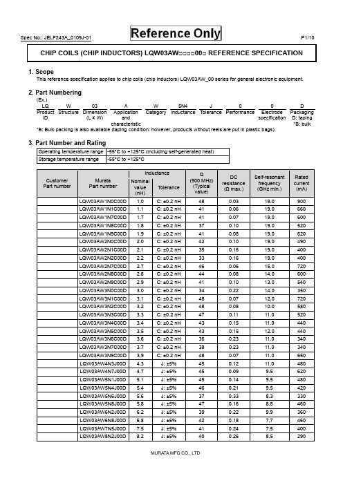
CHIP COILS (CHIP INDUCTORS) LQW03AW□□□□00□ REFERENCE SPECIFICATION1. ScopeThis reference specification applies to chip coils (chip inductors) LQW03AW_00 series for general electronic equipment.2. Part Numbering(Ex.)LQ W 03 A W 5N4 J 0 0 DProductID Structure Dimension(L × W)ApplicationandcharacteristicCategory Inductance Tolerance Performance ElectrodespecificationPackagingD: taping*B: bulk*B: Bulk packing is also available (taping condition: however, products without reels are put in plastic bags).3. Part Number and RatingOperating temperature range -55°C to +125°C (including self-generated heat)Storage temperature range -55°C to +125°CCustomer Part numberMurataPart numberInductance Q(900 MHz)(Typicalvalue)DCresistance(Ω max.)Self-resonantfrequency(GHz min.)Ratedcurrent(mA) Nominalvalue(nH)ToleranceLQW03AW1N0C00D1.0C:±0.2nH 48 0.03 19.0 900 LQW03AW1N1C00D1.1C:±0.2nH 41 0.06 19.0 660 LQW03AW1N7C00D1.7C:±0.2nH 41 0.07 19.0 600 LQW03AW1N8C00D1.8C:±0.2nH 37 0.10 19.0 520 LQW03AW1N9C00D1.9C:±0.2nH 41 0.08 19.0 620 LQW03AW2N0C00D2.0C:±0.2nH 42 0.10 19.0 490 LQW03AW2N1C00D2.1C:±0.2nH 35 0.16 19.0 400 LQW03AW2N2C00D2.2C:±0.2nH 33 0.16 19.0 400 LQW03AW2N7C00D2.7C:±0.2nH 46 0.06 15.0 720 LQW03AW2N8C00D2.8C:±0.2nH 44 0.08 14.0 600 LQW03AW2N9C00D2.9C:±0.2nH 41 0.10 13.0 540 LQW03AW3N0C00D3.0C:±0.2nH 34 0.22 14.0 350 LQW03AW3N1C00D3.1C:±0.2nH 48 0.07 12.0 720 LQW03AW3N2C00D3.2C:±0.2nH 48 0.08 10.0 580 LQW03AW3N3C00D3.3C:±0.2nH 47 0.11 11.0 520 LQW03AW3N4C00D3.4C:±0.2nH 43 0.15 11.0 440 LQW03AW3N5C00D3.5C:±0.2nH 43 0.15 12.0 440 LQW03AW3N6C00D3.6C:±0.2nH 36 0.23 11.0 340 LQW03AW3N7C00D3.7C:±0.2nH 38 0.23 11.0 340 LQW03AW3N9C00D3.9C:±0.2nH 48 0.07 11.0 650 LQW03AW4N3J00D4.3 J:±5% 45 0.12 11.0 480 LQW03AW4N7J00D4.7 J:±5% 45 0.09 9.5 620 LQW03AW5N1J00D5.1 J:±5% 45 0.14 9.5 480 LQW03AW5N4J00D5.4 J:±5% 46 0.21 9.5 420 LQW03AW5N6J00D5.6 J:±5% 37 0.33 8.3 330 LQW03AW5N8J00D5.8 J:±5% 47 0.16 8.8 460 LQW03AW6N2J00D6.2 J:±5% 39 0.22 9.9 360 LQW03AW6N8J00D6.8 J:±5% 42 0.18 7.7 460 LQW03AW7N5J00D7.5 J:±5% 41 0.24 7.5 400 LQW03AW8N2J00D8.2 J:±5% 40 0.26 8.5 290Customer Part numberMurataPart numberInductance Q(900 MHz)(Typicalvalue)DCresistance(Ω max.)Self-resonantfrequency(GHz min.)Ratedcurrent(mA)Nominalvalue(nH)ToleranceLQW03AW8N7J00D8.7J:±5% 39 0.42 7.5 290 LQW03AW9N1J00D9.1J:±5% 46 0.22 6.4 460 LQW03AW10NJ00D10.0J:±5% 37 0.46 7.2 250 LQW03AW11NJ00D11.0J:±5% 37 0.47 7.0 260 LQW03AW12NJ00D12.5J:±5% 39 0.54 6.0 280 LQW03AW13NJ00D13.0J:±5% 39 0.54 5.9 280 LQW03AW14NJ00D13.5J:±5% 37 0.53 6.0 240 LQW03AW15NJ00D15.5J:±5% 38 0.60 5.7 230 4. Testing ConditionsUnless otherwise specified Temperature: ordinary temperature (15°C to 35°C)Humidity: ordinary humidity [25% to 85% (RH)]In case of doubt Temperature: 20°C±2°CHumidity: 60% to 70% (RH)Atmospheric pressure: 86 kPa to 106 kPa5. Appearance and DimensionsUnit mass (typical value): 0.23 mg6. MarkingNo marking.7. Electrical PerformanceNo.ItemSpecificationTest method7.1 InductanceMeet chapter 3 ratings.Measuring equipment: Keysight E4991A or the equivalentMeasuring frequency: Inductance 250 MHz 1.0 nH to 3.9 nH 100 MHz 4.3 nH to 15.5 nH Measuring conditions:Measurement signal level: Approx. 0 dBm Measurement terminal distance: 0.3 mm Electrical length: 10.0 mmMeasuring fixture: Keysight 16197APosition the chip coil under test as shown in the measuring example below and connect it to the electrode by applying weight. Measurement example:Measuring method: see "Electrical performance: Measuring method for inductance/Q" in the chapter"16. Appendix".7.2 QMeet chapter 3 ratings.7.3 DC resistance Meet chapter 3 ratings. Measuring equipment: digital multimeter 7.4 Self-resonantfrequency Meet chapter 3 ratings.Measuring equipment: Keysight N5230A or theequivalent7.5 Rated currentProduct temperature rise: 20°C max.Apply the rated current specified in chapter 3.8. Mechanical PerformanceNo.ItemSpecificationTest method8.1 Bending testNo significant mechanical damage or no sign of electrode peeling off shall be observed. Test substrate: glass-epoxy substrate (100 mm × 40 mm × 0.8 mm) Pressurizing speed: 1 mm/sDeflection: 2 mm Holding time: 5 s8.2 VibrationAppearance shall have no significant mechanical damage.Oscillation frequency: 10 Hz to 55 Hz to 10 Hz, for approx. 1 minTotal amplitude: 1.5 mmTest time: 3 directions perpendicular to each other, 2 h for each direction (6 h in total)No.ItemSpecificationTest method8.3 Solderability90% or more of the outer electrode shall be covered with new solder seamlessly. Flux: immersed in ethanol solution [including anactivator with a chlorine conversion value of 0.06(wt)%]with a rosin content of 25(wt)% for 5 s to 10 s. Solder: Sn-3.0Ag-0.5Cu solderPre-heating: 150°C±10°C/60 s to 90 s Solder temperature: 240°C±5°C Immersion time: 4 s±1 s 8.4 Resistance tosoldering heatAppearance: No significant mechanical damage shall be observed.Inductance change rate: within ±5%Flux: immersed in ethanol solution [including anactivator with a chlorine conversion value of 0.06(wt)%] with a rosin content of 25(wt)% for 5 s to 10 s. Solder: Sn-3.0Ag-0.5Cu solderPre-heating: 150°C±10°C/60 s to 90 s Solder temperature: 270°C±5°C Immersion time: 5 s±1 sPost-treatment: left at a room condition for 24 h±2 h9. Environmental PerformanceThe product is soldered on a substrate for test. No. Item Specification Test method9.1 Heat resistanceAppearance: No significant mechanicaldamage shall be observed.Inductance change rate: within ±5%Q change rate: within ±20%Temperature: 125°C±2°CTest time: 1000 h (+48 h, -0 h)Post-treatment: left at a room condition for 24 h±2 h 9.2 Cold resistanceAppearance: No significant mechanical damage shall be observed.Inductance change rate: within ±5% Q change rate: within ±20%Temperature: -55°C±2°CTest time: 1000 h (+48 h, -0 h)Post-treatment: left at a room condition for 24 h±2 h9.3 HumidityAppearance: No significant mechanical damage shall be observed.Inductance change rate: within ±5% Q change rate: within ±20%Temperature: 70°C±2°CHumidity: 90% (RH) to 95% (RH) Test time: 1000 h (+48 h, -0 h)Post-treatment: left at a room condition for 24 h±2 h 9.4 Temperature cycle Appearance: No significant mechanicaldamage shall be observed.Inductance change rate: within ±5% Q change rate: within ±20%Single cycle conditions:Step 1: -55°C±2°C/30 min±3 minStep 2: ordinary temperature/10 min to 15 min Step 3: +125°C±2°C/30 min±3 minStep 4: ordinary temperature/10 min to 15 min Number of testing: 10 cyclesPost-treatment: left at a room condition for 24 h±2 h10. Specification of Packaging10.1 Appearance and dimensions of tape (8 mm width/paper tape)A (0.52)B (0.65) t 0.75 max.(in mm)10.2 Taping specificationsPacking quantity (Standard quantity) 10000 pcs/reelPacking method The products are placed in embossed cavities of a base tape and sealed by a cover tape.Feed hole position The feed holes on the base tape are on the right side when the cover tape is pulled toward the user. JointThe base tape and the cover tape are seamless.Number of missing productsNumber of missing products within 0.025% of the number per reel or 1 pc., whichever is greater, and are not continuous. The specified quantity per reel is kept.10.3 Break down force of tapeBreak down force of cover tape5 N min.10.4 Peeling off force of cover tapeSpeed of peeling off 300 mm/minPeeling off force0.1 N to 0.6 N (The lower limit is for typical value.)10.5 Dimensions of leader section, trailer section and reelA vacant section is provided in the leader (start) section and trailer (end) section of the tape for the product. The leader section is further provided with an area consisting only of the cover tape (or top tape). (See the diagram below.)10.6 Marking for reelCustomer part number, Murata part number, inspection number (*1), RoHS marking (*2), quantity, etc. *1 Expression of inspection No.: □□ ○○○○(1) (2) (3)(1) Factory code(2) Date First digit: year/last digit of yearSecond digit: month/Jan. to Sep.→1 to 9, Oct. to Dec.→O, N, D Third, Fourth digit: day (3) Serial No.*2 Expression of RoHS marking: ROHS- Y ( ) (1) (2)(1) RoHS regulation conformity(2) Murata classification number10.7 Marking on outer box (corrugated box)Customer name, purchasing order number, customer part number, Murata part number, RoHS marking (*2), quantity, etc.FCover tapetape165°to 180゜10.8 Specification of outer boxDimensions of outer box(mm) Standard reel quantity in outer box (reel)WDH186 186 935* Above outer box size is typical. It depends on a quantity of an order.11. Caution11.1 Restricted applicationsPlease contact us before using our products for the applications listed below which require especially high reliability for the prevention of defects which might directly cause damage to the third party's life, body or property. (1) Aircraft equipment (2) Aerospace equipment (3) Undersea equipment (4) Power plant controlequipment(5) Medical equipment (6) Transportation equipment (vehicles, trains, ships, etc.) (7) Traffic signal equipment (8) Disaster/crimeprevention equipment(9) Data-processing equipment (10) Applications of similar complexity and/or reliability requirements to the applications listed in the above11.2 Precautions on ratingAvoid using in exceeded the rated temperature range, rated voltage, or rated current.Usage when the ratings are exceeded could lead to wire breakage, burning, or other serious fault.11.3 Inrush currentIf an inrush current (or pulse current or rush current) that significantly exceeds the rated current is applied to the product, overheating could occur, resulting in wire breakage, burning, or other serious fault.11.4 Corrosive gasPlease refrain from use since contact with environments with corrosive gases (sulfur gas [hydrogen sulfide, sulfur dioxide, etc.], chlorine, ammonia, etc.) or oils (cutting oil, silicone oil, etc.) that have come into contact with the previously stated corrosive gas environment will result in deterioration of product quality or an open from deterioration due to corrosion of product electrode, etc. We will not bear any responsibility for use under these environments.12. Precautions for UseThis product is for use only with reflow soldering. It is designed to be mounted by soldering. If you want to use other mounting method, for example, using a conductive adhesive, please consult us beforehand.Also, if repeatedly subjected to temperature cycles or other thermal stress, due to the difference in the coefficient of thermal expansion with the mounting substrate, the solder (solder fillet part) in the mounting part may crack.The occurrence of cracks due to thermal stress is affected by the size of the land where mounted, the solder volume, and the heat dissipation of the mounting substrate. Carefully design it when a large change in ambient temperature is assumed.12.1 Land dimensionsThe following diagram shows the recommended land dimensions for reflow soldering.The land dimensions are designed in consideration of electrical characteristics and mountability. Use of other landdimensions may preclude achievement of performance. In some cases, it may result in poor solderability, including positional shift. If you use other land pattern, consider it adequately.a 0.23b 0.65c 0.4(in mm)WDLabelH12.2 Flux and solder usedFlux• Use a rosin-based flux that includes an activator with a chlorine conversion value of 0.06(wt)% to 0.1(wt)%. • Do not use a highly acidic flux with a halide content exceeding 0.2(wt)% (chlorine conversion value). • Do not use a water-soluble flux.Solder• Use Sn-3.0Ag-0.5Cu solder.• Standard thickness of solder paste: 80 μm to 100 μmIf you want to use a flux other than the above, please consult our technical department.12.3 Soldering conditions (reflow)• Pre-heating should be in such a way that the temperature difference between solder and product surface is limited to 150°C max.Cooling into solvent after soldering also should be in such a way that the temperature difference is limited to 100°C max. Insufficient pre-heating may cause cracks on the product, resulting in the deterioration of product quality. • Standard soldering profile and the limit soldering profile is as follows.The excessive limit soldering conditions may cause leaching of the electrode and/or resulting in the deterioration of product quality.Standard profile Limit profilePre-heating 150°C to 180°C/90 s±30 s 150°C to 180°C/90 s±30 s HeatingAbove 220°C/30 s to 60 sAbove 230°C/60 s max.Peak temperature 245°C±3°C 260°C/10 s Number of reflow cycles2 times2 times12.4 Reworking with soldering ironDo not perform reworking with a soldering iron on this product.12.5 Solder volumeSolder shall be used not to increase the volume too much.An increased solder volume increases mechanical stress on the product. Exceeding solder volume may cause the failure of mechanical or electrical performance.Limit ProfileStandard Profile90s±30s230℃260℃245℃±3℃220℃30s~60s60s max.180150Temp.(s)(℃)Time.12.6 Product's locationThe following shall be considered when designing and laying out PCBs.(1) PCB shall be designed so that products are not subject to mechanical stress due to warping the board. [Products direction]Products shall be located in the sideways direction (length: a < b) to the mechanical stress.(2) Components location on PCB separationIt is effective to implement the following measures, to reduce stress in separating the board.It is best to implement all of the following three measures; however, implement as many measures as possible to reduce stress.Contents of measures Stress level(1) Turn the mounting direction of the component parallel to theboard separation surface.A > D *1 (2) Add slits in the board separation part.A >B (3) Keep the mounting position of the component away from the board separation surface.A > C*1 A > D is valid when stress is added vertically to the perforation as with hand separation. If a cutting disc is used, stress will be diagonal to the PCB, therefore A > D is invalid.(3) Mounting components near screw holesWhen a component is mounted near a screw hole, it may be affected by the board deflection that occurs during the tightening of the screw.Mount the component in a position as far away from the screw holes as possible.12.7 Handling of substrateAfter mounting products on a substrate, do not apply any stress to the product caused by bending or twisting to the substrate when cropping the substrate, inserting and removing a connector from the substrate or tightening screw to the substrate. Excessive mechanical stress may cause cracking in the product.Bending Twisting〈Poor example 〉〈Good example〉ba12.8 CleaningThe product shall be cleaned under the following conditions.(1) The cleaning temperature shall be 60°C max. If isopropyl alcohol (IPA) is used, the cleaning temperature shall be 40°Cmax.(2) Perform ultrasonic cleaning under the following conditions. Exercise caution to prevent resonance phenomenon inmounted products and the PCB.Item RequirementPower 20 W/L max.Time 5 min max.Frequency 28 kHz to 40 kHz(3) CleanerAlcohol-based cleaner: IPAAqueous agent: PINE ALPHA ST-100S(4) There shall be no residual flux or residual cleaner. When using aqueous agent, rinse the product with deionized wateradequately and completely dry it so that no cleaner is left.* For other cleaning, consult our technical department.12.9 Storage and transportationStorage period Use the product within 12 months after delivery.If you do not use the product for more than 12 months, check solderability before using it.Storage conditions • The products shall be stored in a room not subject to rapid changes in temperature and humidity.The recommended temperature range is -10°C to +40°C. The recommended relative humidityrange is 15% to 85%.Keeping the product in corrosive gases, such as sulfur, chlorine gas or acid, oxidizes theelectrode, resulting in poor solderability or corrosion of the coil wire of the product.• Do not keep products in bulk packaging. Doing so may cause collision between the products orbetween the products and other products, resulting in core chipping or wire breakage.• Do not place the products directly on the floor; they should be placed on a palette so that they arenot affected by humidity or dust.• Avoid keeping the products in a place exposed to direct sunlight, heat or vibration.Transportation Excessive vibration and impact reduces the reliability of the products. Exercise caution whenhandling the products.12.10 Resin coatingThe inductance value may change due to high cure-stress of resin to be used for coating/molding products.A wire breakage issue may occur by mechanical stress caused by the resin, amount/cured shape of resin, or operatingcondition etc. Some resin contains some impurities or chloride possible to generate chlorine by hydrolysis under some operating condition may cause corrosion of wire of coil, leading to wire breakage.So, please pay your careful attention when you select resin in case of coating/molding the products with the resin.Prior to use the coating resin, please make sure no reliability issue is observed by evaluating products mounted on your board.12.11 Handling of product• Sharp material such as a pair of tweezers or other material such as bristles of cleaning brush, shall not be touched to the winding portion to prevent the breaking of wire.• Mechanical shock should not be applied to the products mounted on the board to prevent the breaking of the core.12.12 Handling with mounting equipment• With some types of mounting equipment, a support pin pushes up the product from the bottom of the base (paper) tape when the product is sucked with the pick-up nozzle.When using this type of equipment, detach the support pin to prevent the breaking of wire on the product.• In some cases, the laser recognition function of the mounting equipment may not recognize this product correctly.Please contact us when using laser recognition. (There is no problem with the permeation and reflection type.)13. Note(1) Please make sure that your product has been evaluated in view of your specifications with our product being mounted toyour product.(2) You are requested not to use our product deviating from the reference specifications.(3) The contents of this reference specification are subject to change without advance notice. Please approve our productspecifications or transact the approval sheet for product specifications before ordering.14. AppendixElectrical performance: Measuring method for inductance/Q (Q measurement is applicable only when the Q value is included in the rating table.)Perform measurement using the method described below. (Perform correction for the error deriving from the measuring terminal.)(1) Residual elements and stray elements of the measuring terminal can be expressed by the F parameter for the 2-poleterminal as shown in the figure below.(2) The product's impedance value (Zx) and measured impedance value (Zm) can be expressed as shown below, by usingthe respective current and voltage for input/output.Zm=V1I1Zx=V2I2(3) Thus, the relationship between the product's impedance value (Zx) and measured impedance value (Zm) is as follows.Zx=αZm-β1-ZmΓHere,α=D/A=1β=B/D=Zsm - (1 - Yom Zsm) ZssΓ=C/A=YomZsm: measured impedance of short chipZss: residual impedance of short chip (0.480 nH)Yom: measured admittance when measuring terminal is open (4) Calculate inductance Lx and Qx using the equations shown below.Lx=Im (Zx)2πfLx: inductance of chip coilQx: Q of chip coilf: measuring frequencyQx=Im (Zx) Re (Zx)。
罗克韦尔自动化-2080-um002_-zh-e.pdf-Micro830、Micro850 和 M

Micro830、Micro850 和 Micro870可编程控制器Micro810 控制器产品目录号 2080-LC10-12AWA、2080-LC10-12QWB、2080-LC10-12DWD、2080-LC10-12QBBMicro820 控制器产品目录号 2080-LC20-20AWB、2080-LC20-20AWBR、2080-LC20-20QWB、2080-LC20-20QWBR、2080-LC20-20QBB、2080-LC20-20QBBRMicro830 控制器产品目录号 2080-LC30-10QWB、2080-LC30-10QVB、2080-LC30-16AWB、2080-LC30-16QWB、2080-LC30-16QVB、2080-LC30-24QWB、2080-LC30-24QVB、2080-LC30-24QBB、2080-LC30-48AWB、2080-LC30-48QWB、2080-LC30-48QVB、2080-LC30-48QBBMicro850 控制器产品目录号 2080-LC50-24AWB、2080-L50E-24AWB、2080-LC50-24QWB、2080-L50E-24QWB、2080-LC50-24QVB、2080-L50E-24QVB、2080-LC50-24QBB、2080-L50E-24QBB、2080-LC50-48AWB、2080-L50E-48AWB、2080-LC50-48QWB、2080-L50E-48QWB、2080-LC50-48QWBK、2080-L50E-48QWBK、2080-LC50-48QVB、2080-L50E-48QVB、2080-LC50-48QBB、2080-L50E-48QBBMicro870 控制器产品目录号 2080-LC70-24AWB、2080-L70E-24AWB、2080-LC70-24QWB、2080-L70E-24QWB、2080-LC70-24QWBK、2080-L70E-24QWBK、2080-L70E-24QWBN、2080-LC70-24QBB、2080-L70E-24QBB、2080-LC70-24QBBK、2080-L70E-24QBBK、2080-L70E-24QBBN2罗克⻙尔⾃动化出版物2080-UM002M-ZH-E - 2022 年4 月Micro830、Micro850 和 Micro870 可编程控制器⽤⼾⼿册重要⽤⼾须知在安装、配置、操作或维护本产品之前,请阅读本文档以及“其他资源”章节所列的文档,了解关于安装、配置和操作该设备的信息。
星辰科技 SDOCK2U33EB 2.5 3.5 英寸 SATA HDD 双接口 USB 3.0 e

DE: Bedienungsanleitung - FR: Guide de l'utilisateur - ES: Guía del usuario - IT: Guida per l'uso - NL: Gebruiksaanwijzing - PT:Guia do usuário - SDOCK2U33EBUSB 3.0/eSATA Dual 2.5/3.5” SATA HDD Dock with UASP*actual product may vary from photosFCC Compliance StatementThis equipment has been tested and found to comply with the limits for a Class B digital device, pursuant to part 15 of the FCC Rules. These limits are designed to provide reasonable protection against harmful interference in a residential installation. This equipment generates, uses and can radiate radio frequency energy and, if not installed and used in accordance with the instructions, may cause harmful interference to radio communications. However, there is no guarantee that interference will not occur in a particular installation. If this equipment does cause harmful interference to radio or television reception, which can be determined by turning the equipment off and on, the user is encouraged to try to correct the interference by one or more of the following measures:• Reorient or relocate the receiving antenna.• Increase the separation between the equipment and receiver.• Connect the equipment into an outlet on a circuit different from that to which the receiver is connected.• Consult the dealer or an experienced radio/TV technician for help.Use of Trademarks, Registered Trademarks, and other Protected Names and Symbols This manual may make reference to trademarks, registered trademarks, and other protected names and/or symbols of third-party companies not related in any way to . Where they occur these references are for illustrative purposes only and do not represent an endorsement of a product or service by , or an endorsement of the product(s) to which this manual applies by the third-party company in question. Regardless of any direct acknowledgement elsewhere in the body of this document, hereby acknowledges that all trademarks, registered trademarks, service marks, and other protected names and/or symbols contained in this manual and related documents are the property of their respective holders.Table of ContentsProduct Overview (1)Front View (1)Rear View (1)Introduction (2)Packaging Contents (2)System Requirements (2)Installation (3)Docking Station Installation (3)Drive Installation (3)Drive Removal (4)Docking Station Operation (5)Drive Initialization (5)LED Indicator (6)Disconnecting the Hard Drive (6)Specifications (7)Technical Support (8)Warranty Information (8)Product OverviewFront ViewRear VieweSATA portPower adapter portPower buttonPower /Activity LEDsIntroductionPackaging Contents• 1 x USB 3.0/eSATA to Dual 2.5/3.5in SATA hard drive docking station• 1 x USB 3.0 Cable• 1 x eSATA cable• 1x Universal Power Adapter (NA/UK/EU)• 1x Instruction ManualSystem Requirements• Computer system with available USB or eSATA port• Up to two 2.5” or 3.5” SATA Hard Drives (HDD) or Solid State Drives (SSD)• Microsoft® Windows® 2000/XP/Server 2003/Vista/Server 2008 R2/7/8/8.1 (32/64-bit), Apple® Mac® OS 9.x/10, Chrome OS or Linux®InstallationWARNING! Hard drives and docking stations require careful handling. If you are not careful with your hard disk, lost data may result. Always handle your hard drive and docking station with caution. Be sure that you are properly grounded by wearing an anti-static strap when handling computer components or discharge yourself of any static electricity build-up by touching a large grounded metal surface (such as the computer case) for several seconds.Docking Station Installation1. Connect the Dock to an available power outlet, using the provided power adapter.2. Connect the Dock to your computer system, using the provided USB/eSATA cable.Drive Installation1. Carefully align and insert the2.5” or3.5” SATA drive(s) you wish to dock in the desired hard drive slot on the docking station, such that the SATA power and data connectors on the drive are properly aligned with the corresponding connectors inside the hard drive slot.2. Press the power button so the docking station is turned on.Note: The single power button operates both drive slots.3. Once the drives have been installed and the docking station has been powered on, the computer Operating System will automatically recognize the drive(s) and it will be accessible as though it were installed in the system internally.Note: If your computer fails to automatically recognize your drive it is likely your drive has not been initialized or formatted correctly. (See Drive Initialization in Software operation for further instructions.)Drive RemovalWARNING! Ensure your hard drive(s) has been disconnected from your computer operating system prior to attempting drive removal. Failure to properly disconnect your drive may result in lost data or drive damage. (See Disconnecting the Hard Drive in Docking Station Operation for further instructions.)1. Turn off the docking station by pressing the power button.2. Press the eject button that corresponds with the drive you wish to remove.3. Carefully grasp the ejected drive and lift it upwards until the bottom of the drive has completely risen above the hard drive slot.4. Safely and carefully store your drive in a secure location. (See your hard drive manual for proper storage instructions.)Note: We recommend ensuring the docking station is powered off before any drive is physically inserted or removed from the docking station. If two drives are docked simultaneously, and one drive is removed while the docking station is still powered on the other drive will momentarily disconnect from your computer which could cause drive damage or loss of data if other drive is still mounted.Docking Station OperationDrive InitializationPrior to using your installed drive, it will need to be initialized and formatted to the operating system requirements in order for your computer system to recognize it.1. From the main Windows desktop, right-click on “My Computer” (“Computer” in Vista/ 7 / 8/ 8.1), then select Manage. In the new Computer Management window, select Disk Management from the left window panel.2. A dialog window will automatically appear, asking you to initialize the drive. Depending on the version of Windows, it will give you the option of either creating an “MBR” or “GPT” disk.Note: GPT (GUID partition) is required for drives larger that 2TB but is not compatible with some older operating systems, while MBR is supported by newer and older operating systems.3. Once initialized, locate the Disk that says it is “Unallocated” (check the listed hard drive capacity to confirm it’s the correct hard drive) and then right-click in the section that says “Unallocated” and select “New Partition”.4. Follow the on screen prompts to initialize the drive in the format of your choice. LED IndicatorThe docking station offers an LED indicator for each drive, to enable you to monitor drive activity. When the docking station is powered on, the LED will illuminate. While the hard drive is being accessed, the LED will blink. Do not remove your drive from the docking station while the LED is flashing, as it could damage to your drive, resulting in data loss.Disconnecting the Hard DriveWindows1. Select the “Safely remove Hardware and Eject Media” icon, located in the task bar.2. Select the storage device from the list that appears.3. Wait for the message indicating that it is now safe to remove the device.Note: Removing the connected drive prior to receiving notification that it is safe to do so, could result in losing or corrupting data stored on the drive. Once the Safe to Remove Hardware message appears, please remove the drive from the docking station. (See Drive Removal.)Mac OS XTo safely disconnect the attached drive from the host computer, close any windows listing the contents of the removable drive. Once all windows are closed, click on the USB storage icon on the desktop, and drag it to the Trash Can icon on the desktop. Allow 5 seconds before physically removing the drive from the docking station.SpecificationsTechnical Support’s lifetime technical support is an integral part of our commitment to provide industry-leading solutions. If you ever need help with your product, visit /support and access our comprehensive selection of online tools, documentation, and downloads.For the latest drivers/software, please visit /downloads Warranty InformationThis product is backed by a two year warranty.In addition, warrants its products against defects in materials and workmanship for the periods noted, following the initial date of purchase. During this period, the products may be returned for repair, or replacement with equivalent products at our discretion. The warranty covers parts and labor costs only. does not warrant its products from defects or damages arising from misuse, abuse, alteration, or normal wear and tear.Limitation of LiabilityIn no event shall the liability of Ltd. and USA LLP (or their officers, directors, employees or agents) for any damages (whether direct or indirect, special, punitive, incidental, consequential, or otherwise), loss of profits, loss of business, or any pecuniary loss, arising out of or related to the use of the product exceed the actual price paid for the product. Some states do not allow the exclusion or limitation of incidental or consequential damages. If such laws apply, the limitations or exclusions contained in this statement may not apply to you.Instruction Manual8Hard-to-find made easy. At , that isn’t a slogan. It’s a promise. is your one-stop source for every connectivity part you need. From the latest technology to legacy products — and all the parts that bridge the old and new — we can help you find the parts that connect your solutions.We make it easy to locate the parts, and we quickly deliver them wherever they need to go. Just talk to one of our tech advisors or visit our website. You’ll be connected to the products you need in no time.Visit for complete information on all products and to access exclusive resources and time-saving tools. is an ISO 9001 Registered manufacturer of connectivity and technology parts. was founded in 1985 and has operations in the United States, Canada, the United Kingdom and Taiwan servicing a worldwide market.。
金笛M1806-ME 4G全网通版短信收发设备说明书
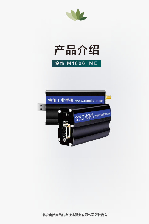
产品介绍金笛M1806-M E Array北京春笛网络信息技术服务有限公司版权所有公司介绍产品零缺陷,售后零服务。
不需要服务的产品才是更好的产品。
缺图01金笛是一家集硬件、软件研发、生产、销售一体的高科技企业,注册资金2000万元,产品行销海内外,业内享有极高的美誉度。
MU-106M1806-NC5M1806-ME MG301-FT MC323RS232MC323MG301M1206B-FTMG35-FTM1806-NC5M1806-ME M1806N-NC5MG35-N M1806N-ME MG301-N小一体机MN1604大一体机MN1408RJ45M1206BMG35产品概述03把方便留给客户,把麻烦留给我们。
能简单才不简单。
提供高可靠的短信软硬件,立志把可靠性做到极致。
产品经过十多年的技术积累和积淀,不断迭代升级,日趋完善。
产品选型图02金笛M1806-ME是一款4G全网通版短信收发设备,分为串口款和USB口两款。
金笛M1806-ME支持移动/联通/电信4G网络向下兼容3G/2G网络采用工业级4G模块串口款USB口款小巧精致95g2秒/条ESD保护高效传输稳定可靠采用高品质4G模块稳定性千锤百炼超级稳定接口自由选择串口或者USB口内嵌看门狗功能内嵌看门狗功能,确保设备24小时稳定运行、不宕机。
设计的目的,就是一切自动化、智能化。
连接简单,多系统兼容适用于所有主要的操作系统Windows全系列Linux发送速度快4G短信猫的优势是工业级M2M应用的不二选择2秒/条是普通2G短信猫的3倍信号好频段多兼容性好外壳采用铝合金材质,防刮防指纹,坚固耐用磨砂工艺,高端时尚,质感十足金笛M1806N-ME和M1806-ME的区别是前者是网口,后者是USB或者串口。
M1806N-MEM1806-ME对比防伪标签设计激光防伪金笛正品质量保证天线接头设计采用纯铜接头材质信号更强更稳定卡槽设计抽屉式卡托设计完美防尘强劲ESD保护超宽温度范围金笛M1806-ME有着超宽温度范围(-40°C ~+85°C),核心模块采用强劲的ESD保护,直接放电空气±10KV,接触±5KV,充分的FLASH 保护机制和多重防呆机制,保证设备可以长期稳定运行。
- 1、下载文档前请自行甄别文档内容的完整性,平台不提供额外的编辑、内容补充、找答案等附加服务。
- 2、"仅部分预览"的文档,不可在线预览部分如存在完整性等问题,可反馈申请退款(可完整预览的文档不适用该条件!)。
- 3、如文档侵犯您的权益,请联系客服反馈,我们会尽快为您处理(人工客服工作时间:9:00-18:30)。
机械专业论文参考选题
覆盖件切断工艺分析及模具设计
椭圆形拉深件工艺分析及模具设计
基于MATLAB的曲柄滑块机构的运动仿真与分析
基于MATLAB的曲柄摇杆机构的运动仿真与分析
基于MATLAB的双曲柄机构的运动仿真与分析
基于MATLAB的双摇杆机构的运动仿真与分析
基于UG的曲柄滑块机构的运动仿真与分析
基于UG的曲柄摇杆机构的运动仿真与分析
基于UG的双曲柄机构的运动仿真与分析
基于UG的双摇杆机构的运动仿真与分析
并联机械手运动仿真软件——实体仿真模型建立
并联机械手运动仿真软件——运算模块设计
并联机械手运动仿真软件——动态仿真模块设计
并联机械手运动仿真软件——框架设计
开放式教学机器人单关节控制系统硬件分析及软件探索
《电工学》CAI课件开发
两坐标数控工作台运动控制的NURBS插补器
车床微进给刀架设计
工业机器人控制系统研究
两坐标数控工作台运动控制的样条插值算法及应用
专用车床主轴箱部件设计
汽车头枕调节执行器设计
汽车头枕调节执行器设计
数控车程序加工仿真
数控铣程序加工仿真
四轴运动开发平台控制系统研究
普通车床主轴箱部件设计
谐波传动性能研究
柔轮径向变形对啮合侧隙的影响
齿轮标准压力角对啮合侧隙的影响
径向谐波传动研究
端面谐波传动研究
封闭谐波传动研究
MM7140机床结构改进设计研究
个人电脑显示器保健架机构运动学设计与分析研究
基于PLC的立体仿形机床刀架控制系统设计研究
精密镗削刀具补偿机构设计研究
天然气开关阀漏气实验装置设计
主动振动采油机理研究
自动清理鞋底器设计
二自由度汽车悬挂系统LQ控制研究
助学型多媒体CAI课件制作
工程中的隔振降噪研究
双曲轴合模机构结构设计
四自由度汽车悬挂系统主动控制研究
CK6136型数控车床后置处理器的开发
RBT-2SZ01_100L直角坐标教学机器人的教学实验研究和设计
RBT-6T/S01S教学机器人的教学实验研究和设计
RBT-4T/S01四轴运动控制开发平台的教学实验研究和设计
九阳豆浆机降噪技术的研发
铝塑分离技术的研究
XK0824型数控铣床后置处理器的开发
节电节水型太阳能热水器防冻器的研发
潜艇降噪技术的研发(潜艇噪音、降噪技术)
贵州黔西煤矿设备安全调查(煤矿设备安全)。