F1760电力用户快速使用指南
林肯电力(Lincoln Electric)LN-15线电馈器IM734说明书

OPERATOR’SMANUALCopyright © 2002 Lincoln Global Inc.LN-15 WIRE FEEDERIM734July, 2002For use with machines having Code Number:10865Safety Depends on YouLincoln arc welding and cut t ing equipment is designed and built with safety in mind. However, your overall safet y can be increased by proper inst allat ion ... and t hought ful opera-t ion on your par t .DO NOT INSTALL, OPERATE OR REPAIR THIS EQUIPMENT WITHOUT READING THIS MANUAL AND THE SAFETY PRECAUTIONS CONTAINED THROUGHOUT.And,most import ant ly, t hink before you act and be careful.This manual covers equipment which is nolonger in production by The Lincoln Electric Co. Speci cations and availability of optional features may have changed.Mar ‘95Mar. ‘93for selecting a QUALITY product by Lincoln Electric. We want you to take pride in operating this Lincoln E lectric Company product ••• as much pride as we have in bringing this product to you!Read this Operators Manual completely before attempting to use this equipment. Save this manual and keep it handy for quick reference. Pay particular attention to the safety instructions we have provided for your protection.The level of seriousness to be applied to each is explained below:vvGUNS AND CABLES ASSEMBLIESFIGURE A.1Table A.2 Trigger Connector J1 (5 Pin)8 Pin Control Cable Receptacle5 Pin Trigger ConnectorWELDING CABLE (ELECTODE)WELDING CABLE (WORK)1. Turn the reel or spool until the free end of the elec-trode is accessible.5. Remove the inner wire guide.Insert the new inner wire guide, groove side out,over the two locating pins in the feed plate.Install a drive roll on each hub assembly and lockby rotating the triangular drive roll retaining mecha-nism.Install the outer wire guide by aligning it with thepins and tightening the knurled thumbscrews.9. Close the idle arm and engage the idle roll pressurearm. Adjust the pressure appropriately.• Do not attach the work clip to the roll cage or bottom skids. The work clip is energized any time the output of the welding power source is “ON ”, even when the feeder is not welding.• Do not touch electrically live part or electrode with skin or wet clothing.• Insulate yourself from work and ground.• Always wear dry insulating gloves.• The serviceability of a product or structure uti-lizing the LN-15 wire feeder is and must be the sole responsibility of the builder/user. Many variables beyond the control of The Lincoln Electric Company affect the results obtained in using the LN-15 wire feeder. These variables include, but are not limited to, welding proce-dure, plate chemistry and temperature, weld-ment design, fabrication methods and service requirements. The available range of the LN-15wire feeder may not be suitable for all applica-tions, and the builder/user is and must be sole-ly responsible for welding settings.--------------------------------------------------------------------- FUMES AND GASSES can be dangerous.Keep your head out of fumes. Use ventilation or exhaust to remove fumes from breathing zone.WELDING SPARKS can cause fire or explosion.Keep flammable material away.RAYS can burn.Wear eye, ear and body protec----------------------------------------------------------------------SEE ADDITIONAL WARNING INFORMATION UNDER ARC WELDING SAFETY PRECAUTIONS AND IN THE FRONT OF THIS OPERATING MAN-UAL.----------------------------------------------------------------------WIRE FEEDER POSITIVE OUTPUT NEGATIVE OUTPUTINPUT POWER DIRECT CURRENTOPEN CIRCUIT VOLTAGE INPUT VOLTAGE OUTPUT VOLTAGE INPUT CURRENTOUTPUT CURRENT PROTECTIVE GROUND WARNING OR CAUTIONU 0U 1U 2I 1I 2TABLE B.1FIGURE B.112 34 56Press the GAS PURGE switch again to save theFEEDGAS PURGEFEEDGAS PURGEConstant Current Power SourceCurrent WireFeederWFSCTWD Welding Cable(Electrode)LN-15GUN AND CABLEASSEMBLYFIGURE B.4 CC WIRE SPEED SETTINGb. Referring to the graph located above the Mode switch (also shown in Figure B.4):1.Select the horizontal line representing the DE-SIRED IN/MIN. for the welding procedure. (Seeexample arrow line for 375 in/min.)2.Select the diagonal line representing the ARCVOLTS to be used for the welding procedure. (Seeexample arrow line for 29 volts.)3.Determine the vertical line representing the CCWIRE SPEED SETTING where the above two linescross. (See example arrow line for 450.)c. Adjust the WFS display to the value determined inStep (3) above (450 for example used).MAKING A WELD•Connect the work cable to the metal to be welded. The work cable must make good electrical contact to the work. The work must also be grounded as stated in "Arc Welding Safety Precautions."• Connect the LN-15 electrode cable to the power source for the polarity and process to be used. Check that the appropriate power source settings are made for the procedure to be used. (Refer to the power source operating and connection instruc-tions.)• Place the LN-15 conveniently near the work area in a safe location to minimize exposure to weld spatter and to avoid sharp bends in the gun cable.• Connect the control cable to the power source..•Be sure the proper contact tip, liner and nozzle for the wire size being used, is in the gun and cable assembly.• Turn on the welding power source, connect the shielding gas supply hose (if used), and open valve to shielding gas supply.• Set equipment to desired welding procedure.• Cut the electrode within approximately .40" (10mm) of the end of the contact tip for solid wire and within .75" (19mm) of the extension guide for cored wire.• Position the electrode over the joint. The end of the electrode should be slightly off the work.• Lower welding helmet, close the gun trigger and begin welding. Hold the gun so the contact tip to work distance gives the correct electrical stickout as required for the procedure being used.• To stop welding, release the gun trigger and the pull the gun away from the work.FACTORY INSTALLED EQUIPMENT•K1500-2 Gun Receiver Bushing.OPTIONAL EQUIPMENT• Control Cable Extensions•Adapter Cable for Control Cable to Terminal Strip Power Sources• Gun Receiver Bushings• Control CableELECTRIC SHOCK can kill.•Do not operate with coversremoved.•Turn off power source beforeinstalling or servicing.•Do not touch electrically hotparts.• Turn the input power to the welding power source off at the fuse box before working in the terminal strip.•Only qualified personnel should install, use or service this equipment.ROUTINE MAINTENANCERoutine maintenance consists of periodically blowing out the machine, using a low pressure airstream, to remove accumulated dust and dirt from inside the feeder.PERIODIC MAINTENANCE•Replace the drive rolls and inner wire guide when they are worn.• Replace the pig tail if the insulation is cut, abraded or damaged.CALIBRATION SPECIFICATIONAll calibration is factory set on the LN-15.To verify the wire feed speed:• Assemble a .045 (1.2mm) drive roll kit into the LN-15.• Load a spool of .045 (1.2mm) electrode and thread the electrode through the wire drive.• Adjust the wire feed speed to 300 in/min (7.62m/min).• Press the COLD INCH switch and measure the actual wire feed speed with a calibrated wire feed speed tachometer.• The measured wire feed speed should be within 2% of the set value.To verify the voltage display:•Set the welding power source and LN-15 to a CV procedure that gives steady "spray" transfer in the arc.•While a weld is being made, measure the voltage from the feedplate to work.• The displayed voltage on the LN-15 should be with-in 2% of the measured value.This Troubleshooting Guide is provided to help you locate and repair possible machine malfunctions.Simply follow the three-step procedure listed below.Step 1.LOCATE PROBLEM (SYMPTOM).Look under the column labeled “PROBLEM (SYMP-TOMS)”. This column describes possible symptoms that the machine may exhibit. Find the listing that best describes the symptom that the machine isexhibiting.Step 2.POSSIBLE CAUSE.The second column labeled “POSSIBLE CAUSE ” lists the obvious external possibilities that may contribute to the machine symptom.Step 3.RECOMMENDED COURSE OF ACTIONThis column provides a course of action for the Possible Cause, generally it states to contact your local Lincoln Authorized Field Service Facility.If you do not understand or are unable to perform the Recommended Course of Action safely, contact your local Lincoln Authorized Field Service Facility.HOW TO USE TROUBLESHOOTING GUIDEService and Repair should only be performed by Lincoln Electric Factory Trained Personnel.Unauthorized repairs performed on this equipment may result in danger to the technician and machine operator and will invalidate your factory warranty. For your safety and to avoid Electrical Shock, please observe all safety notes and precautions detailed throughout this manual.__________________________________________________________________________Now Available...12th EditionThe Procedure Handbook of Arc WeldingWith over 500,000 copies of previous editions published since 1933, the Procedure Handbook is considered by many to be the “Bible ” of the arc welding industry.This printing will go fast so don ’t delay. Place your order now using the coupon below.The hardbound book contains over 750 pages of welding information, techniques and procedures. Much of this material has never been included in any other book.A must for all welders, supervisors, engineers and designers. Many welding instructors will want to use the book as a reference for all students by taking advantage of the low quantity discount prices which include shipping by 4th class parcel post.$15.00postage paid U.S.A. MainlandHow To Read Shop DrawingsThe book contains the latest information and application data on the American Welding Society Standard Welding Symbols. Detailed discussion tells how engineers and draftsmen use the “short-cut ” language of symbols to pass on assembly and welding information to shop personnel.Practical exercises and examples develop the reader ’s ability to visualize mechanically drawn objects as they will appear in their assembled form.187 pages with more than 100 illustrations. Size 8-1/2” x 11”Durable, cloth-covered board binding.$4.50postage paid U.S.A. MainlandNew Lessons in Arc WeldingLessons, simply written, cover manipulatory techniques;machine and electrode characteristics; related subjects,such as distortion; and supplemental information on arc welding applications, speeds and costs. Practice materials,exercises, questions and answers are suggested for each lesson.528 pages, well illustrated, 6” x 9” size, bound in simulated,gold embossed leather.$5.00postage paid U.S.A. MainlandNeed Welding Training?The Lincoln Electric Company operates the oldest and most respected Arc Welding School in the United States at its corporate headquarters in Cleveland, Ohio. Over 100,000stu-dents have graduated. Tuition is low and the training is “hands on ”For details write:Lincoln Welding School 22801 St. Clair Ave.Cleveland, Ohio 44117-1199.and ask for bulletin ED-80 or call 216-383-2259 and ask for the Welding School Registrar.Lincoln Welding SchoolBASIC COURSE $700.005 weeks of fundamentalsThere is a 10%discount on all orders of $50.00 or more for shipment at one time to one location.Orders of $50 or less before discount or orders outside of North America must be prepaid with charge, check or money order in U.S. Funds Only.Prices include shipment by 4th Class Book Rate for U.S.A. Mainland Only.Please allow up to 4 weeks for delivery.UPS Shipping for North America Only.All prepaid orders that request UPS shipment please add:$5.00For order value up to $49.99$10.00For order value between $50.00 & $99.99$15.00For order value between $100.00 & $149.00For North America invoiced orders over $50.00 & credit card orders, if UPS is requested, it will be invoiced or charged to you at cost.Outside U.S.A. Mainland order must be prepaid in U.S. Funds. Please add $2.00 per book for surface mail or $15.00 per book for air parcel post shipment.METHOD OF PAYMENT:(Sorry, No C.O.D. Orders)CHECK ONE:Name:_______________________________________________Please Invoice (only if order is over $50.00)Address:_______________________________________________Check or Money Order Enclosed, U.S. Funds only _______________________________________________Credit Card - Telephone:_______________________________________________Signature as it appears on Charge Card:Account No.Exp Date|_|_||_|_|______________________Month YearUSE THIS FORM TO ORDER:Order from:BOOK DIVISION, The Lincoln Electric Company, 22801 St. Clair Avenue, Cleveland, Ohio 44117-1199BOOKS OR FREE INFORMATIVE CATALOGS Telephone: 216-383-2211 or, for fastest service, FAX this completed form to: 216-361-5901.Lincoln Welding School Titles:Price Code QuantityCost(ED-80)New Lessons in Arc Welding $5.00L Seminar Information Procedure Handbook “Twelfth Edition ”$15.00PH (ED-45)How to Read Shop Drawings $4.50H Educational Video Information Incentive Management $5.00IM (ED-93) A New Approach to Industrial Economics $5.00NA James F. Lincoln Arc Welding The American Century of John C. Lincoln $5.00AC Foundation Book Information Welding Preheat Calculator $3.00WC-8(JFLF-515)Pipe Welding Charts $4.50ED-89SUB TOTALAdditional Shipping Costs if anyTOTAL COSTJapaneseChineseKoreanArabicREAD AND UNDERSTAND THE MANUFACTURER’S INSTRUCTION FOR THIS EQUIPMENT AND THE CONSUMABLES TO BE USED AND FOLLOW YOUR EMPLOYER’S SAFETY PRACTICES.SE RECOMIENDA LEER Y ENTENDER LAS INSTRUCCIONES DEL FABRICANTE PARA EL USO DE ESTE EQUIPO Y LOS CONSUMIBLES QUE VA A UTILIZAR, SIGA LAS MEDIDAS DE SEGURIDAD DE SU SUPERVISOR.LISEZ ET COMPRENEZ LES INSTRUCTIONS DU FABRICANT EN CE QUI REGARDE CET EQUIPMENT ET LES PRODUITS A ETRE EMPLOYES ET SUIVEZ LES PROCEDURES DE SECURITE DE VOTRE EMPLOYEUR.LESEN SIE UND BEFOLGEN SIE DIE BETRIEBSANLEITUNG DER ANLAGE UND DEN ELEKTRODENEINSATZ DES HER-STELLERS. DIE UNFALLVERHÜTUNGSVORSCHRIFTEN DES ARBEITGEBERS SIND EBENFALLS ZU BEACHTEN.JapaneseChineseKoreanArabicLEIA E COMPREENDA AS INSTRUÇÕES DO FABRICANTE PARA ESTE EQUIPAMENTO E AS PARTES DE USO, E SIGA AS PRÁTICAS DE SEGURANÇA DO EMPREGADOR.••• Sales and Service through Subsidiaries and Distributors Worldwide •Cleveland, Ohio 44117-1199 U.S.A. TEL: 216.481.8100 FAX: 216.486.1751 WEB SITE: 。
三相能耗计 Telstar CT 快速启动指南说明书
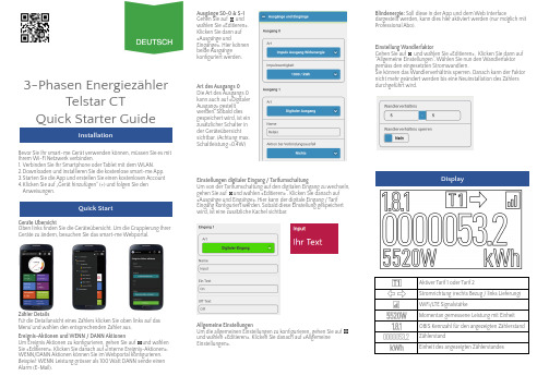
3-Phasen EnergiezählerTelstar CTQuick Starter GuideInstallationBevor Sie Ihr smart-me Gerät verwenden können, müssen Sie es mit Ihrem Wi-Fi Netzwerk verbinden.1.Verbinden Sie Ihr Smartphone oder Tablet mit dem WLAN.2.Downloaden und installieren Sie die kostenlose smart-me App.3.Starten Sie die App und erstellen Sie einen kostenlosen Account4.Klicken Sie auf …Gerät hinzufügen“ (+) und folgen Sie den Anweisungen.Quick StartGera t e U b ersichtOben links finden Sie die Geräteübersicht. Um die Gruppierung IhrerGeräte zu ändern, besuchen Sie das smart-me Webportal.Zahler DetailsFurdie Detailansicht eines Zahlers klicken Sie oben links auf das Menuund wah len den entsprechenden Zahler aus.Ereignis-Aktionen und WENN / DANN AktionenUm Ereignis Aktionen zu konfigurieren, gehen Sie auf und wa h len Sie «Editieren». Klicken Sie danach auf «Interne Ereignis-Aktionen».WENN/DANN Aktionen können Sie im Webportal konfigurieren.Beispiel:WENN Leistung grösser als 100 Watt DANN sende einen Alarm (E-Mail).Ausgänge S0-0 & S-1Gehen Sie auf und wa h len Sie «Editieren».Klicken Sie dann auf «Ausga n ge undEinga n ge». Hier ko n nen beide Ausga n ge konfiguriert werden.Art des Ausgangs 0Die Art des Ausgangs 0kann auch auf «Digitaler Ausgang» gestellt werden. Sobald dies gespeichert wird, ist ein zusa t zlicher Schalter in der Geräteübersicht sichtbar. (Achtung max.Schaltleistung <0.4W)Einstellungen digitaler Eingang / TarifumschaltungUm von der Tarifumschaltung auf den digitalen Eingang zu wechseln,gehen Sie auf und wa h len «Editieren» . Klicken Sie danach auf «Ausga n ge und Einga n ge». Hier kann der digitale Eingang / Tarif Eingang konfiguriert werden. Sobald diese Einstellung gespeichert wird, ist eine zusa t zliche Kachel sichtbar.Allgemeine EinstellungenUm die allgemeinen Einstellungen zu konfigurieren, gehen Sie auf und wa h len «Editieren». Klicken Sie danach auf «Allgemeine Einstellungen».Blindenergie:Soll diese in der App und dem Web Interfacedargestellt werden, kann dies hier aktiviert werden (nur mo g lich mit Professional Abo).Einstellung WandlerfaktorGehen Sie aufund wa h len Sie «Editieren». Klicken Sie dann auf “Allgemeine Einstellungen”. Wählen Sie nun den Wandlerfaktor gemäss den eingesetzten Stromwandlern.Sie können das Wandlerverhältnis sperren. Danach kann der Faktor nicht mehr geändert werden bis eine Neuinstallation des Zählers durchgeführt wird.DisplayAktiver Tarif 1 oder Tarif 2Stromrichtung (rechts Bezug / links Lieferung)WiFi/LTE Signalsta r keMomentan gemessene Leistung mit EinheitOBIS Kennzahl für den angezeigten Zählerstand ZählerstandEinheit des angezeigten ZählerstandesDisplayanzeige AblaufDer Za h ler hat ein rollendes Display.Die unten beschriebenen Punkte werden nacheinander angezeigt und wiederholt.1)Za h lerstand (OBIS Code gefolgt von Za h lerstand)1.8.1(A+) Wirkenergie Bezug Tarif 11.8.2(A+) Wirkenergie Bezug Tarif 22.8.1(A-) Wirkenergie Lieferung Tarif 12.8.2(A-) Wirkenergie Lieferung Tarif 21.8.0:5A (A+) Wirkenergie Total Bezug 5A Basis 2.8.0:5A (A-) Wirkenergie Total Lieferung 5A Basis 5.8.0(Q1) Induktive Blindenergie Bezug total 6.8.0(Q2) Kapazitive Blindenergie Bezug total 7.8.0(Q3) Induktive Blindenergie Lieferung total 8.8.0(Q4) Kapazitive Blindenergie Lieferung total2)Wandlerfaktor (OBIS Code gefolgt von Informationen)0.4.2 Wandlerfaktor (inkl. S0 Impulse / kWh)3)Firmware (OBIS Code gefolgt von Informationen)C.1.6Ch: 2218Firmware Checksumme 0.2.0V 1.1Firmware Version4)Fehleranzeige (OBIS Code gefolgt von Fehlermeldungen)C.60.9Fraud Flag (möglicher Betrugsversuch erkannt)PhL: 1nur Phase L1 angeschlossen PhL: 2nur Phase L2 angeschlossen PhL: 3nur Phase L3 angeschlossen PhL: 23Phase L1 nicht angeschlossen PhL: 13Phase L2 nicht angeschlossen PhL: 12Phase L3 nicht angeschlossenKorrekte Phasenreihenfolge:Zahlen leuchten statisch Falsche Phasenreihenfolge:Zahlen blinkenTechnische DatenBetriebsspannung3 x 230/400 VAC Strombereich I min -I ref (I max)0.01-1(6)AGenauigkeitsklasse B (1%)Betriebstemperatur −25 bis +70 °C Lagertemperatur −40 bis +85 °C LuftfeuchtigkeitJahresmittel 75%,kurzzeitig 95%,nicht kondensierendProdukt Zertifizierung CE, MID 2014/32/EU, RED Messgeräte Kategorie CAT IIISchutzart Klemmen: IP20Gehäuse: IP51Umweltklassen Mechanisch: M1Elektrisch: E2Zählerart4-Quadrantenzähler(Wirk-und Blindenergie,Bezug und Lieferung)Impulsausgang S0-0Opto Power MOSFET, P MAX = 0.4 W 12 - 48VDC / 12 - 230 VACImpulswertigkeit S0-01’000 oder 10’000 Impulse/kWh Leistungsausgang S-1Relais, P MAX = 1’500 Wmax. 48VDC / max. 230 VAC Tarifeingang E112 - 48VDC / 12 - 230 VACTechnische Irrtümer und Änderungen vorbehaltenSicherheitshinweiseDie Sicherheitshinweise sind unter allen Umsta n den einzuhalten:●Das Gera t ist fu r die Verwendung in Geba u den vorgesehen.●Das Gera t ist fu r den Betrieb an einem trockenen, staubfreien Ort ohne direkte Sonneneinstrahlung vorgesehen.●Ha u figes An- und Ausschalten kann die Lebensdauer elektrischer Gera t e verku r zen. Richten Sie nur dann eine automatische Schaltung mit ha u figen An- und Ausschaltvorga n gen ein, wenn dieangeschlossenen Gera t e dafu r ausgelegt sind. Fu r entsprechende Scha d en an angeschlossenen Gera t en wird nicht gehaftet.●Bei der Installation oder beim Wechseln des Gera t es mu s sen die Leiter, die an das Gera t angeschlossen werden, spannungsfrei sein.●Das Beru h ren unter Spannung stehender Teile ist lebensgefa h rlich!Deshalb sind die entsprechenden Vorsicherungen zu entfernen und so aufzubewahren, dass andere Personen diese nicht unbemerkt wiedereinsetzen ko n nen.●Die Installation des Gera t es darf nur von fachkundigem und entsprechend geschultem Personal erfolgen.●Die ortsu b lichen Sicherheits- und Werkvorschriften sind einzuhalten.●Der Energiezähler muss in einem Schrank mit der Schutzart IP51 oder besser installiert werden●Isolierung der Netzanschlussklemmen: Verstärkt ●Isolierung von S1, S0-0 und E1 Klemmenanschlüsse:Wenn eine Klemme mit Spannungen über SELV verwendet wird, ist eine verstärkte Isolierung für alle Klemmen erforderlich.AnschlussschemaT1Taste für die InstallationT2SpezialfunktionenKurz : Wird T2 >2s gedrückt, schaltet die grüne LED-Lampe ein / aus. Wenn diese aktiviert ist, zeigt diese den Verbindungszustand anGrün leuchtend: verbunden mit smart-me CloudGrün blinkend: Verbindungsaufbau oder keine Verbindung Lang : Wird T2 >8s gedrückt, wird die Anzeige der Leistung zwischen Wirk- & Blindleistung umgeschaltet. Ausserdem wechselt die Eichimpuls-LED zwischen Wirkenergie und Blindenergie.Sehr lang : Wird T2 >14s gedrückt, wird der S0-0Impulsausgang zwischen Wirkleistung und Blindleistung umgeschaltet.ACHTUNG:Diese Einstellung ändert nur die Anzeige auf dem Display,nicht in der smart-me Cloud (App und Webseite).Soll die Blindenergie in der Cloud angezeigt werden,muss dies in den allgemeinen Einstellungen gemacht werden.E1Tarifeingang, potentialfreiTarif 1:0V (oder nicht angeschlossen)Tarif 2:12 -48VDC / 12 - 230VAC einstellbar als digitaler EingangS0-0S0 Impulsausgang, potentialfreiPower MOSFET mit P MAX = 0.4 W einstellbar als digitaler AusgangS-1Leistungsausgang, potentialfreiRelais mit P MAX = 1’500 WQUICK INSTALLATION GUIDE3-Phasen EnergiezählerTelstar CTDEUTSCH23.07.2021LETTENSTRASSE 9 | 6343 ROTKREUZ | SWITZERLAND********************|+41(0)415110970Bei generellen Fragen sind weitere Informationen auf unserer Webseite sowieauf der Wiki-Plattform zu finden:smart-me wiki:。
华立N型三相电子式多功能电能表使用说明书

有功正反向电能计量功能。 4.1.2有功正向电量可编程设置为有功正向、有功反向电量的任意加减
组合。无功正、反向(容感性)电量可编程设置为无功四象限电量 的任意加减组合。 4.2 需量记录功能 记录有功正反向、无功正反向总最大需量、分时最大需量及其发生 时间。需量计算方式可选择区间式或滑差式,需量周期在1~60分钟 之内可设,滑差时间在1~15分钟之内可设。需量周期与滑差时间设
能
+-+ -+-+-+-
端 子
PN 辅助 电源
(
(
秒多 Ⅰ Ⅰ Ⅱ Ⅱ Ⅲ Ⅲ Ⅳ Ⅳ A B A B
信号功能口 远 动 脉 冲 输 出 485Ⅱ 485Ⅰ
(
P-GND AP+ RP+
(
扩 展
测有 无
试
功 测
功 测
地试 试
电
1 2 3 4 5 6 7 8 9 10 11
源
端
子A B C N
电流互感式
互感式:0.002In(1.0) 无功0.003In (2.0) 直接式:0.004In(1.0) 无功0.005In (2.0) 3.6 潜动:具有防潜动逻辑设计。 3.7 重量:2.6kg。 3.8 外形:257.8×171×87 (见图1)。 本仪表的综合指标符合DL/T 614-1997《多功能电能表》标准 的要求。 通信规约符合DL/T 645-1997《多功能电能表通信规约》 的要求。可扩展其他通讯规约。
-3-
PDF 文件使用 "pdfFactory Pro" 试用版本创建 炣
电脑设定

電腦設定(F10)公用程式指南商用桌上型電腦文件編號:361206-AB22004年9月本指南說明如何使用電腦設定(Computer Setup)。
本工具可於安裝新硬體時用於重新設定和修改電腦預設設定,並供維護之用。
© Copyright 2004 Hewlett-Packard Development Company, L.P.此處所含的資訊如有更改,恕不另行通知。
Microsoft和Windows是Microsoft Corporation在美國和其他國家/地區的商標。
HP產品與服務的保固僅列於隨產品及服務所附的明確保固聲明中。
本文件的任何部份都不可構成任何額外的擔保。
HP不負責本文件在技術上或編輯上的錯誤或疏失。
本文件包含的專屬資訊受到著作權法所保護。
未經Hewlett-PackardCompany書面同意,不得複印、複製本文件的任何部份,或將本文件的任何部份翻譯成其他語言。
Å警告事項:這種方式的文字表示如果不依照所指示的方法來操作,可能會導致人身傷害或喪失生命。
Ä注意事項:這種方式的文字表示如果不依照所指示的方法來操作,可能會導致設備損壞或資訊遺失。
電腦設定(F10)公用程式指南商用桌上型電腦第二版(2004年9月)第一版(2004年5月)文件編號:361206-AB2目錄電腦設定(F10)公用程式電腦設定(F10)公用程式 . . . . . . . . . . . . . . . . . . . . . . . . . . . . . . . . . . . . . . . . . . . . . . . . 1使用電腦設定(F10)公用程式 . . . . . . . . . . . . . . . . . . . . . . . . . . . . . . . . . . . . . . . . . 3檔案(File). . . . . . . . . . . . . . . . . . . . . . . . . . . . . . . . . . . . . . . . . . . . . . . . . . . . . . . . . . 4系統資訊(System Information) . . . . . . . . . . . . . . . . . . . . . . . . . . . . . . . . . . . . . 4關於(About) . . . . . . . . . . . . . . . . . . . . . . . . . . . . . . . . . . . . . . . . . . . . . . . . . . . . 4設定時間和日期(Set Time and Date) . . . . . . . . . . . . . . . . . . . . . . . . . . . . . . . . 4複製設定(Replicated Setup). . . . . . . . . . . . . . . . . . . . . . . . . . . . . . . . . . . . . . . . 4預設設定(Default Setup) . . . . . . . . . . . . . . . . . . . . . . . . . . . . . . . . . . . . . . . . . . 5套用預設值並離開(Apply Defaults and Exit). . . . . . . . . . . . . . . . . . . . . . . . . . 5忽略變更並離開(Ignore Changes and Exit). . . . . . . . . . . . . . . . . . . . . . . . . . . . 5儲存變更後離開(Save Changes and Exit). . . . . . . . . . . . . . . . . . . . . . . . . . . . . 5儲存(Storage). . . . . . . . . . . . . . . . . . . . . . . . . . . . . . . . . . . . . . . . . . . . . . . . . . . . . . . 5裝置組態(Device Configuration). . . . . . . . . . . . . . . . . . . . . . . . . . . . . . . . . . . . 5儲存體選項(Storage Options) . . . . . . . . . . . . . . . . . . . . . . . . . . . . . . . . . . . . . . 7DPS自動測試(DPS Self-Test). . . . . . . . . . . . . . . . . . . . . . . . . . . . . . . . . . . . . . 9開機順序(Boot Order) . . . . . . . . . . . . . . . . . . . . . . . . . . . . . . . . . . . . . . . . . . . . 9安全性(Security). . . . . . . . . . . . . . . . . . . . . . . . . . . . . . . . . . . . . . . . . . . . . . . . . . . 10設定密碼(Setup Password). . . . . . . . . . . . . . . . . . . . . . . . . . . . . . . . . . . . . . . . 10開機密碼(Power-On Password). . . . . . . . . . . . . . . . . . . . . . . . . . . . . . . . . . . . 10密碼選項(Password Options). . . . . . . . . . . . . . . . . . . . . . . . . . . . . . . . . . . . . . 10預先開機授權(Pre-Boot Authorization). . . . . . . . . . . . . . . . . . . . . . . . . . . . . . 10智慧型外殼(Smart Cover) . . . . . . . . . . . . . . . . . . . . . . . . . . . . . . . . . . . . . . . . 10嵌入式安全性(Embedded Security). . . . . . . . . . . . . . . . . . . . . . . . . . . . . . . . . 11電腦設定(F10)公用程式指南 iii目錄裝置安全性(Device Security). . . . . . . . . . . . . . . . . . . . . . . . . . . . . . . . . . . . . . 11網路服務開機(Network Service Boot) . . . . . . . . . . . . . . . . . . . . . . . . . . . . . . 11系統(System IDs) . . . . . . . . . . . . . . . . . . . . . . . . . . . . . . . . . . . . . . . . . . . . . . . 11磁碟機/光碟機鎖安全性(DriveLock Security)功能 . . . . . . . . . . . . . . . . . . . 12資料執行保護(Data Execution Prevention)功能 . . . . . . . . . . . . . . . . . . . . . . 12主要開機記錄安全性(Master Boot Record Security). . . . . . . . . . . . . . . . . . . 13儲存主要開機記錄(Save Master Boot Record). . . . . . . . . . . . . . . . . . . . . . . . 13還原主要開機記錄(Restore Master Boot Record). . . . . . . . . . . . . . . . . . . . . . 13電源 . . . . . . . . . . . . . . . . . . . . . . . . . . . . . . . . . . . . . . . . . . . . . . . . . . . . . . . . . . . . . 14 OS電源管理 . . . . . . . . . . . . . . . . . . . . . . . . . . . . . . . . . . . . . . . . . . . . . . . . . . . 14硬體電源管理 . . . . . . . . . . . . . . . . . . . . . . . . . . . . . . . . . . . . . . . . . . . . . . . . . . 14溫度 . . . . . . . . . . . . . . . . . . . . . . . . . . . . . . . . . . . . . . . . . . . . . . . . . . . . . . . . . . 14進階(Advanced)*. . . . . . . . . . . . . . . . . . . . . . . . . . . . . . . . . . . . . . . . . . . . . . . . . . . 15開機選項(Power-On Options) . . . . . . . . . . . . . . . . . . . . . . . . . . . . . . . . . . . . . 15BIOS開機(BIOS Power-On) . . . . . . . . . . . . . . . . . . . . . . . . . . . . . . . . . . . . . . 17內建裝置(Onboard Devices) . . . . . . . . . . . . . . . . . . . . . . . . . . . . . . . . . . . . . . 17PCI裝置(PCI Devices). . . . . . . . . . . . . . . . . . . . . . . . . . . . . . . . . . . . . . . . . . . 17匯流排選項(Bus Options) . . . . . . . . . . . . . . . . . . . . . . . . . . . . . . . . . . . . . . . . 18裝置選項(Device Options). . . . . . . . . . . . . . . . . . . . . . . . . . . . . . . . . . . . . . . . 18PCI VGA組態(PCI VGA Configuration) . . . . . . . . . . . . . . . . . . . . . . . . . . . . 19還原組態設定. . . . . . . . . . . . . . . . . . . . . . . . . . . . . . . . . . . . . . . . . . . . . . . . . . . . . . . . . 20方法一:Flash ROM CMOS儲存與還原特色─使用電源開關覆蓋 . . . . . . . . 20方法二:儲存至可抽換式媒體及從可抽換式媒體中復原 . . . . . . . . . . . . . . . . . 21iv 電腦設定(F10)公用程式指南電腦設定(F10)公用程式電腦設定(F10)公用程式使用電腦設定(F10)公用程式來完成下列工作:■變更原廠預設設定。
F1760功能及使用介绍

控制 LED 指示灯
©2010 Fluke Co.
25
仪器和PC的通讯连接
第一步 最后:
将设置好的测试任务发送到仪器,只需点击 初始化按钮即可
第二步
初始化
成功连接后显示信息
©2010 Fluke Co.
26
实时模式:确认线路连接和设置
1、连接并设置好仪器后,打开实时模式
©2010 Fluke Co.
第二步:选择记录的数据 EN50160 :根据标准对各项参数要求进行测量和监测。1008/周,10分钟数据。 天:日间隔记录。从00:00:00小时开始。 自由时间间隔:用户自定义记录间隔 10分钟:
事件: 谐波
RMS
示波器 脉动控制信号 瞬变
©2010 Fluke Co. 28
数据分析
谐波。
选择变量
滑动参考
选择该选项,将获得 IEC 61000-4-30标准第3.26和5.4.4 条规定的滑动参考电压,用于检测电压骤降和骤升事件。
©2010 Fluke Co. 17
记录模式
注意:无论触发信号设置与否,EN
50160统计值、1天记录值、自由间隔、 10分钟间隔记录值以及事件都会始终被 记录, 至于其他功能,只有当触发信号 动作时才会被记录。 实例:以平均20 ms的时间间隔持续记 录rms值: 将“延时”和“预触发”时间都设为4秒 ,然后将记录时间选择为10 s。
©2010 Fluke Co.
4
1、仪器的介绍
1.1主要的应用
供电部门 • 供配电系统、电力用户的电网电能质量评估 • 供配电系统、电力用户的电网电能质量问题排除 用电单位,例如电力电子/汽车制造业 • 在用户引入线处监测供电电源的质量 • 揭示设备故障的根源,进行事后补救或预测性维护
电力一体化电源系统操作说明-大连旅顺电力电子

、查询逆变器处于旁路供电状态。
、断开旁路检修开关。
、投上交流输入开关,投上直流输入开关。
4、正常运行时UPS电源屏上交流输出电压表显示的范围为220V左右。
5、UPS开关机时尽量断开输出负荷,以免启动电流过大造成设备损坏。
通信电源屏运行维护、操作说明及注意事项
巡视内容(正常运行时)
7、“合闸延时”用于调整合闸时间。
※ATS备有手动转换把手,控制器故障时可使用此把手转换电源,在控制器正常工作在自动状态时严禁使用此把手操作。
监控器功能说明:
监控器设置参数设定以及历史记录控件。
其中参数设定用于交流电源报警上下限值以及传感器变比设置。需要调整于交流电源报警上下限值时在屏幕上点击此控件进入设置界面设置。
直流部分运行维护、操作说明及注意事项
巡视内容(正常运行时)
操作说明
参数设定及查看信息
注意事项
直流屏:
(1)高频开关电源模块:共3个指示灯,从左至右依次为:
电源指示灯,正常时为绿色常亮;
故障指示灯,正常时灭,故障时红色常亮;
过温指示灯,正常时灭。模块温度过高时红色常亮。
(2)模块输入开关:正常闭合。
(3)模块输出开关:正常闭合。
按键功能说明:
1、“自动”按钮用于ATS电动/手动工作模式转换。
2、“常用”投入按钮用于投入常用电源(手动方式下)。
3、“备用”投入按钮用于投入备用电源(手动方式下)。
4、“再扣”投入按钮用于使ATS常备用电源进入双分状态(手动方式下)。
5、“分闸延时”用于调整分闸时间。
6、“欠压调节”用于调整欠电压切换值。
电力一体化电源系统操作说明
编制:刘亮
多功能表操作说明

多功能表操作说明Acuvim390、330、327操作说明:1.查看电流、电压参数:V/A键,实现查看和翻屏功能2.查看功率参数:,实现查看系统有功功率P(KW)、无功功率Q(KVar)、视在功率S (KVA)3.查看电度:,实现查看系统有功电能Ep(KWh)、无功电能Eq(Kvarh)、视在电能Es(KVAh),其中常规看的电度为:系统有功电能Acuvim188操作说明:1.查看电流、电压、功率参数:V/A键,实现查看和翻屏功能2.查看电度:F键,实现查看系统有功电能Ep(KWh),其中常规看的电度为:系统有功电能仪表常见问题排查(确保接线正确情况下):1.电流测量不准情况:检测CT设置参数是否跟实际CT额定参数一致2.电压测量不准情况:检测pT设置参数是否跟实际pT额定参数一致3.电度测量不准情况:首先检测电流、电压测量参数是否正确,否则调整相应参数设置然后检查实际接线与系统设置接线方式是否正确,否则调整相应参数设置系统参数设置:Acuvim390、330、327设置:同时按F和V/A键,进入密码登陆界面,出厂默认密码为0000,如下图:按V/A键翻至仪表接线方式设定页。
“仪表接线方式”可设定为“3Ln”、“3LL”、“2LL”和“1Ln”。
相关内容请参考用户使用手册。
如下图:接线方式设定为3Ln。
使用“↑”键或者“↓”键进行接线方式切换。
按“V/A”键确认并进入下一屏设定页。
按V/A键进入系统参数设置,然后使用V/A键翻屏,翻到第四屏(PT设置界面),设置PT一次侧额定电压值,如下图按V/A键翻到如下界面,设置PT二次侧额定电压值(电压直接接入情况下,设定值与一次侧相同)按V/A键翻到如下界面,设置CT一次侧额定电流值,设定值应与现场CT一侧额定值一致按V/A键翻到如下界面,设置CT二次侧额定电流值,仪表出厂前根据客户要求设定5A或1A的固定值,其值不可更改AO模拟量的参数设置:在系统参数设置模式下,同时按F和按键,进入如下界面:模拟量AO1跟随量的设定界面:(根据仪表型号不同,其具体功能也不同,选定恰当的变送跟随量,如下表)按V/A键进入下图设置界面,为满足不同用户的需求,Acuivm 300 扩展AO提供变送范围选择。
集合式电力电容器说明书

集合式电力电容器说明书无锡全心电力电容器有限公司WUXI TRASING POWER CAPACITOR CO., LTD.1 概述1.1该集合式并联电容器主要用于10kV、35kV工频电力系统进行无功补偿。
以提高电网功率因数,减少线损,改善电压质量,充分发挥发电、供电设备的效率。
由于该产品采用集合式结构,因而占地面积小,安装维护方便,可靠性高,运行费用省,特别是适用于大型变电站户外集中补偿及城市电网改造。
1.2该产品目前有BFMH、BAMH等2个系列。
1.2.1 该产品型号的代表意义如下:B□□H□-□-□W户外式相数额定容量(千乏)额定电压(千伏)集合式介质代号(M表示全膜介质)浸渍剂代号(F表示苯基二甲苯基乙烷,A表示苄基甲苯)并联电容器1.2.2 示例:BAMH11/√3-8000-3W表示:浸渍苄基甲苯,全膜介质的集合式并联电容器,额定电压为11/√3kV,额定容量为8000kvar,三相,户外式。
1.3使用环境条件1.3.1安装地点海拔高度不超过1000米。
注:用于海拔高于1000米地区的电容器,订货时请特别注明。
1.3.2 使用环境温度a. 用苯基二甲苯基乙烷浸渍的产品:-25℃~+45℃;b. 用苄基甲苯浸渍的产品:-40℃~+45℃。
1.3.3抗震强度:水平方向0.25g,垂直方向0.125g。
1.3.4 周围不含有对金属有严重腐蚀气体或蒸汽,无导电尘埃,无剧烈的机械振动。
2主要性能指标2.1集合式并联电容器的主要参数和外形尺寸见附表1(10KV),图1-4;附表2(35),图9-12。
电容器的成套布置方式灵活多样,故仅提供部分典型布置形式以供参考,见图5-8和图13-15。
图中场地尺寸均有裕度,在保证安全距离的情况下,用户可以做适当的调整,也可根据自己的情况选择其他的布置方式。
2.2稳态过电压电容器的连续运行电压为1.00Un,且能在如表1所规定的稳定过电压下运行相应的时间。
- 1、下载文档前请自行甄别文档内容的完整性,平台不提供额外的编辑、内容补充、找答案等附加服务。
- 2、"仅部分预览"的文档,不可在线预览部分如存在完整性等问题,可反馈申请退款(可完整预览的文档不适用该条件!)。
- 3、如文档侵犯您的权益,请联系客服反馈,我们会尽快为您处理(人工客服工作时间:9:00-18:30)。
©2008 Fluke Co.
检测电压暂降。通过同时记录电压和电流值,可为判断是否因系统负载变 动导致电压暂降提供分析数据,或者用来判断压降是否由配电电网的其他 支路所引起。
18
测量方式1
1 – 到现场
3 – 将仪器带回办公室,下载 数据并分析
2 – 设置记录仪并连接仪器,检查 LED 指示灯,启动测量
变比、存储器的分配、可自定义算法 • 10 MHz,6000 Vpk 波形捕获能力。不会漏掉发生时间很短的瞬时现象 • 2 GB 数据存储空间,而且通过存储器管理功能存储时间一目了然! • 智能附件,仪器自动检测到附件的类型及标定数据,即插即用 • 坚固的现场应用设计,安全耐用!
©2008 Fluke Co.
F1760专家级电能质量评估工具
快速使用指南
目录
1、仪器的介绍 2、应用软件的安装及仪器的连接 3、仪器的设置 4、中文分析软件的使用 5、中文报表软件的使用 6、使用中常见问题
©2008 Fluke Co.
2
1、仪器的介绍 1.1主要的应用
供电部门 • 供配电系统、用户的电能质量评估 • 供配电系统、用户的电能质量问题排障
滑动参考 选择该选项,将获得 IEC 61000-4-30标准第3.26和5.4.4 条规定的滑动参考电压,用于检测电压骤降和骤升事件。
©2008 Fluke Co.
15
记录模式
©2008 Fluke Co.
16
触发器设置
触发器设置界面
红色指示灯: 该触发信号未定 义阈值
绿色指示灯: 该触发信号已 定义阈值
1 – 在办公室设置好记录仪 2 – 记录仪进行测量
备注:下载数据过程中 不会中断或影响测量
3 – 下载数据并分析
©2008 Fluke Co.
21
连接仪器
以太网
TCP/IP/DHCP 点-点 或通过 网络连接至PQ
Analyze
GPS
时间同步接收机, 套件中内置
USB 2.0
电源
主开关
主开关能防止误动作。
详见随附的报表软件光盘中的使用手册
©2008 Fluke Co.
8
USB驱动安装注意事项
选择安装USB驱动软件,注意选择: USB Virtual Network,见上图
通过USB连接仪器时,见上图,注意选择: USB Virtual Network Adapter #2
©2008 Fluke Co.
用电部门,电力电子/汽车制造业 • 在用户引入线处监测供电电源的质量 • 揭示设备故障的根源,进行事后补救或预测性维护
谐波治理及无功补偿专家 • 治理前对供电质量进行检测,评估,出具治理方案 • 治理后对治理效果进行验证,出具效果报告
©2008 Fluke Co.
3
1、仪器的介绍 1.2系统组成
通讯线缆:以太网、 RS232、USB
4、 F1760软件的使用 4.2数据导出
第一步:打开存储的测量数据,选择 自定义时间间隔的数据
第二步:选择选项—设置导出
第三步:设置导出设置,相应的也要选择自定义时间间隔。其余不用更改
©2008 Fluke Co.
26
4、 F1760软件的使用 4.2数据导出
第一步:选择需要导出的数据区间,两条红 色线之间的数据将被导出
• 检测峰值电压、电流或功率。 如果功率到达设定峰值,则提 醒关闭大容量负载。
备注: 更多的典型应用请查阅软件 使用说明书
• 该触发类型非常合适各种干扰分析和故障排查,因为绝大多数电能质量问题都 会导致电信号波形突然发生变化。 通过记录的波形数据,我们通常可以找出失 真的原因: 电容器组切换、换相失真、电网振荡以及中压系统接地故障通常都 会引起波形的显著变化。
刷新率可调。利用该功能可检查仪器设置、快速概览
• 包括标记功能 • 上/下偏差
• 仪器能自动检测到是否连接和连接的是哪种电压和电流传感器
©2008 Fluke Co.
7
2、软件的安装 2.1 分析软件的安装
• 将仪器随附的软件光盘放入光驱,等待自动安装或手动双击 setup.exe按照提示步骤进行安装
©2008 Fluke Co.
19
测量方式 2
1 – 在办公室设置好记录仪
4 – 将记录仪带回办公室, 下载数据并分析
2 – 到现场
©2008 Fluke Co.
3 – 连接好记录仪, 检查 LED 指示灯并 启动
20
测量方式 3
记录仪永久安装于现场,通过以太网或调 制解调器(尚不可用)连接至网络
31
9
报表软件的安装
报表软件文件夹中有详细的软件安 装说明文档
©2008 Fluke Co.
10
仪器的连接-单相
单相测试
不同的测量分类(CAT)
F1760电源和测量类型
©2008 Fluke Co.
11
仪器的连接及设置-三相四线
连接方法:三功率计法,含或不含中 性导体,
设置方法:以电压10KV,电流600A为例 1、硬件设置
©2008 Fluke Co.
功率等
29
常见故障及问题
©2008 Fluke Co.
30
PC无法和仪器通讯?
请按以下步骤确认本地连接的状态
第一步:打开本地连接状态, 点击属性
第二步:选中Internet协议 (TCP/IP),点击属性
第三步:确认常规选项里 均选择了自动获取
©2008 Fluke Co.
1、连接并设置好仪器后,打开实时模式
实时模式
2、实时模式 • 示波器显示功能,可进行线路连接和设置的检查 • 察看运行中发生的事件 • 瞬变
©2008 Fluke Co.
24
4、F1760软件的使用 4.1下载测试数据
第一步:传输—下载测量数据
第二步:复制记录的数据
©2008 Fluke Co.
25
©2008 Fluke Co.
2、额定值设置
12
仪器的连接及设置-三相三线
连接方法: 两瓦法 (Aron) ,直接
连接
设置方法:以电压10KV,电流600A为例 1、硬件设置
通过PT,CT连接
©2008 Fluke Co.
2、额定值设置
13
3、仪器的设置
启动分析软件PQ Analyze 选择文件
5
1、仪器的介绍 1.4主要技术指标
电源
UPS 数据存储器 采样频率 谐波/间谐波 闪变
AC:83 V~264 V,45~65 Hz DC:100 V~375 V 最大 54 VA 镍氢(NiMH)电池组,7.2 V,2.7 Ah,含电池管理功能 2 GB 闪存,用于固件和数据存储 10.24 kHz,采样率同步于电源频率 1~50次,符合 IEC 61000-4-7:2002标准:200 ms 符合 EN 61000-4-15:2003标准: 10 分钟(Pst),2 小时(Plt)
打开
备注: CBEMA :Computer & Business Equipment Manufacturers Association 计算机和商业设备制造制造协会 ANSI :美国国家标准化组织
©2008 Fluke Co.
说明
选择接线方法,针对每个 通道,定义量程和变比
设置标称值和限值 调节允许误差,按照 CBEMA 或 ANSI 对事件进行分析 设置开始及停止时间 按照各个测试功能需要的测试 时间分配内存
©2008 Fluke Co.
6
1、仪器的介绍-1.5测量功能
统计评估 事件列表 连续记录 触发记录
控制信号 在线模式
按照 EN50160 和 DISDIP 图表,例如 ITIC、CBEMA、ANSI,进行电能质量统计
骤降、骤升、中断和触发事件 可以保存 RMS 值、瞬变和快速瞬变 连续记录平均值、最小值和最大值: 1天、10 分钟、自由间隔,例如 15 分钟、2 小时 RMS 值:10 ms(1/2周期)、20 ms(1 周期)、200 ms(10/12 个周期)或 3 s( 150/180 个周期)。 示波器:全部 8 个通都的采样率为 10.24 kHz 快速瞬变:对于通道 1 ~ 4,采样率从100 kHz 都10 MHz可调 相线和中性导体,电压和电流
第二步:选择测量—ASCII记录报告 发生器
©2008 Fluke Co.
27
5、 报表软件的使用 5.1界面介绍
基本信息 输入
电压等级 及变比
PQ评估 限值
调整因子
©2008 Fluke Co.
数据导入
国标限值
PQ评估 结果
报表导 出键
28
5、 报表软件的使用 5.2导出报表
电压质量
通过率
电流质量
CF 卡插槽*1)
*1) 固件尚不支持。
©2008 Fluke Co.
RS232
*1)
4 个电压 输入
4 个电流输入 /4 个电压输入
22
仪器和PC的通讯连接
第一步
最后: 将设置好的测试任务发送到仪器,只 需点击初始化按钮即可
第二步
初始化
成功连接后显示信息
©2008 Fluke Co.
23
实时模式:确认线路连接和设置
如何激活触发功能? 在信号值设置框上击右键即可激活 每个设置功能界面有详细的解释,请查阅软件
说明书第6章
注意:有时某一事件可能不止满足一种触发条件, 我们建议不要激活过多触发类型, 只要选择最为适合事件记录的触发即可。
©2008 Fluke Co.
Байду номын сангаас17