双闭环直流调速系统外文翻译
外文翻译--直流电动机调速控制
外文翻译--直流电动机调速控制The different speed control systems require a variety of brake systems。
with high starting and braking torque。
quick response。
and a wide range of adjustment degrees for the DC drive system。
Electric braking mode can also be used。
The speed control of a DC motor depends on the ___ zero speed。
either U=0 or Φ=∞。
but the ___。
___ to ce speed。
To increase speed。
U Φ can be increased or decreased.Keywords: ___。
feedback。
______-state n.In many speed control systems。
such as those found in rolling mills and mine winders。
it is often ___ the load to a halt and reverse it frequently。
The rate at which the speed decreases in response to a ced speed demand depends on the amount of stored energy and the braking system employed。
While a small speed control system can use mechanical braking。
this is not ___ and cost of removing the generated heat.To address this issue。
文献翻译—基于PLC直流电动机双闭环调速系统
APLCdm I ( em T ) d I ( e T ) dm I(DDC) DDC 90 PLC DDCPLC DDC PLC PLC11ASR ACR, GT TA TG ASR ACR GT ASR u*n uACR *i u ACR d I I I22U gn U fn U gi U fi U k I d U gi U gi , U gi U gi , PI U gi= U fi U i= U gi- U fi= 0 U gi , PWM , H3.1, PIU gn , U gim U fn U fn< U gn U fn> U gn U ,3.2U gn U gi U kU gn U f n= 0 U n= U gn- U f n U gim U km I d Id I f z( ) Id mI dm , I d I dm ,U gn U f n U n U gim I dm , U f n< U gn U n< 0 U gi U k Ud I dI d I f z Id I f z3 , ,PLC4.1 PLC(Programmable Controller)(Programmable Logic Controller) PLC PC (Personal Computer) PLC,PLC 19664.2 PLCPLCPLC PLC +10%(+15%) PLC(CPU)(CPU) PLC PLC I/O PLC I/O I/O I/O PLC PLC CPU CPU CPU1 PLC2 PLCRS485 Profibus-DP4.3 PLCPLC PLC CPUPLC I/O I/OPLC ( ) RAM I/OI/OI/O RAMI/O I/O I/O I/OPLC CPU I/O PLC4.4 PLCPLC PLC PLC CPU “ ” “ ” “ ”“ ” PLC 1 0 Xn“ ” CPU CPU Yn“ ” PLC PLC PLC PLC“ ”PLCPLC PLC DDC44 PLC PLC PLC FX2 PLC5.1PLC DDC FX2 ——5 6 M8000 D3 D1 D2 “n”56D3 ( D2 ) M8026 ON D3 55.2DDC A/D PLCPLC 10ms 10ms FX2 PLC “ ” 10ms PLC 77N(r/min) FX2 X0S1 X0 S2 ( ms ) 10ms S2 K10 D D5 10ms D5 PLCN D5 Array n——t—— S25.3TA 0 5V DDC A/D PLC I/O A/D VFCU i NS 31 VFC1 3ms 2ms PLC X1 K2 D8 885.4plc 200 300 plc SIEMENS MODICON A-B OMYON GE PLC PLC PLC 2000 PLC 15 20 90% 25 35 12% 2005 PLC 25 35 45PLC 2000 automation research corp PLC PLC 2000 76 2005 76PC PLC PLC PLC PLC 32 I/O PLC SOFT PLC PLC PC-BASEDETHERNET PLC PLC ETHERNET PLC PC PLCPLC Analog Digital A/D D/A PLC A/D D/A PLC I/O PLC ; : PLC PID PLC PID PLC PID PID PLC PLC PLC PLCPLC PLC PLC“ ”BBased on PLC dc motor double closed loopspeed regulation systemDC motor speed control system has a wide application in the systems of metallurgical industry. Such as the reversible rolling mill steel rolling plants, machine repair plant beds as the need to create gantry often reversing speed control system running, As short as possible dc motor starting, braking time is an important factor in increasing productivity. DC motor speed control system in the maximum current dm I (maximum torque em T ) limited conditions, hopes to use to allow the motor overload.Ideally: remain in the current transition process d I (torque e T ) is the maximumallowed. Drag the system as much as possible while enabling the acceleration starting with the greatest reach the steady state speed after letting the current immediately decreased, so that once the load torque equilibrium, which turn into steady state. In fact, the role of the main circuit inductance, the current is not mutated. Under the conditions of the permit in order to achieve the fastest start, the key is to get a maximum value of dm I , can maintain a constant current process, while the best startin the end, to keep the speed constant. Since only the speed involved in the regulation of inputs, therefore, the introduction of the speed and current dual-loop speed control system.And direct digital control (DDC) system is accused of using a computer circuit test parameters and test results compared with the given value, then press the predetermined control law, such as proportional, integral law of operation, the last issue of control signal, through the interface to control the actuator control of industrial objects. Early computer systems the main use of DDC SBC, and now mosthave been used microcontroller. 90 to market the new PLC logic control not only the powerful features, but also has strong data processing capabilities, it can be used for dual loop control of DC drive system of the DDC.PLC control for DC drive system, it not only the analog signal processing system to achieve DDC control logic capable of handling the large number of interface signals, so a machine, fully tap the PLC resource. And PLC systems to develop simple, easy programming, anti-interference ability, high reliability, suitable for work in industrial environments, as long as we reasonably designed to reduce costs, it will be welcomed by the field technicians.First, the speed, the current composition of Double Closed Loop System Speed and current dual-loop speed control system shown in Figure 1.Figure 1 Speed and the current double closed loop speed regulation system From a structural point of view is a double closed-loop system as the inner loop current controller to adjust speed as the outer ring speed and current dual-loop control system. System consists of speed controller ASR, current regulator ACR, trigger system GT, current sensor TA, tachometer generator TG and other components. Which, in order to speed and current feedback are two works, the speed controller ASR output as the input current regulator ACR, then the output current regulator to control the trigger system GT. The role of ASR system: the speed u to follow a given voltage, steady-state static error; from the interference of the role ofchanges in the load; The output limits determine the maximum current amplitude. The role of the system ACR: from the grid voltage fluctuation interference effect. maximum starting current at startup; In the speed regulation process, the current to follow its reference voltage. In fact, the important role of the system ACR is to keep the DC motor armature current in the dynamic process does not exceed the allowable value, the overshoot as possible. As a typical anti-I-system disturbance recovery time is short ten, so the current correction as a typical I-type systems. Also based on the requirements of steady-state non-static, no static error to achieve speed, making speed control system has good anti-interference ability of ten, so the speed loop calibration system into a typical type .Second, the current motor servo system IntroductionThe system uses dual-loop speed control mode, the current loop and speed loop with a common complete system of regulation, its composition is shown in Figure 2.Figure 2 DC motor servo system of the diagramMap: U gn speed reference signal to, U fn the speed feedback signal, U gi for the current reference signal, U fi for the current feedback signal, U k is given PWM current loop signal. System, current feedback using the Hall current sensor, speed is a tachometer generator negative feedback components. Both the double-loop speedcontrol system provides the feedback signal. The role of inner current loop is the motor armature current Id submit to its given value U gi, U gi unchanged when It manifested as constant current regulation, when the U gi changes, it showed with the dynamic regulation. If U gi unchanged, the current loop PI regulator is bound in the U gi = U fi, which U i = U gi - U fi = 0, to achieve No difference adjustment. speed and general single outer loop speed control system is not fundamentally different, the difference is the speed regulator output U gi, where the back does not directly promote the amplifier, but as to the current loop value. two together constitute the cascade control system, through the PWM pulse width modulator to produce square wave pulse control signal, the amplification drive circuit, to control the H-switch amplifier, enabling the motor control. This system can not only control speed, but also control of current, full use of the motor overload, access to fast dynamic response.Third, the double-loop DC Motor Control Unit works3.1 pairs of closed-loop system, the static and dynamic qualityFrom the static characteristics point of view, the current static characteristics of negative feedback have to soften the trend, but there are speed feedback loop on the outside package, the current negative feedback loop for the speed is equivalent to a disturbance, as long as the speed loop magnification is large enough, and there is no saturation, the current negative feedback disturbance can be suppressed. not to mention the speed loop PI regulator is used, the entire system is no static error of the speed control system. In other words, when the speed loop is not saturated, the current negative Static characteristics of the feedback that may have been completely downhill speed regulator integral role in elimination. Once the speed regulator saturation, velocity loop is useless, only works under the current loop, then, system performance, constant current control system, static characteristics show a steep decline.From the dynamic response process, the sudden transient U gn given signal, the speed of negative feedback is very small, approximately zero, the speed regulator is saturated very quickly, limiting the output voltage of the constant U gim, through the current regulator, the motor quickly, starting, and while the feedback voltage U fnincreased speed, but because of the speed loop integral action, as long as or U fn <U gn, the speed loop output amplitude remained unchanged in the limit, until the speed overshoot, that is U fn > U gn, the input offset voltage U becomes negative, the speed loop exit saturation. Therefore, in the whole process increases the speed, the speed has been in a saturated ring, which is equivalent to the speed loop is open-loop state, the system only in the constant current loop under the maximum current value of start. until the overshoot, the speed loop really play a role in the stabilization of speed. Thus, clever use of the speed regulator saturation nonlinearity, in the role of a period of time it partition, the system is basically the starting process in the performance of constant adjustment.In short, the dual loop system in the sudden transition of a given signal the performance of the process control system for the constant value of the current, stable operation in a stable and close to the static error-free performance in speed control system, speed and current played the role of the two regulators get a good static and dynamic quality.3.2 pairs of closed-loop speed control unit worksIn a given voltage U gn sudden starting the process, the speed regulator output voltage is U gi, the current regulator output is U k, the whole process of starting the transition can be divided into three stages.The first stage is the current upswing. In a given voltage U gn sudden, due to mechanical and electrical inertia of the larger motor, the motor had a chance to turn, speed negative feedback voltage U f n = 0, then, U n = U gn - U f n great so that the output of speed controller for the sudden increase in U gim, current regulator output U km, the rapid increase in armature current Id, when the increased Id If z (load current), the motor began to turn, then, armature current rapidly increased to the maximum I dm..The second phase is the phase constant increases the speed. From the current maximum I dm began to rise, to rise to a given value of speed until it is played.The main stage of the process moving. At this stage, the speed loop has been saturated, the speed can not afford the negative feedback regulation, the equivalent of open-loop state, the system performance under the current loop for the constantcurrent regulator, which remains constant current Id value I dm, the motor produces maximum torque, speed increases the speed.The third stage is the speed regulation stage. Speed loop play a role at this stage. The beginning of speed has risen to the given value, speed ring tone and speed for a given voltage U gn negative feedback voltage U f n equilibrium, zero input bias U n. but the output is the integral action is maintained in the limited amplitude U gim, so the motor is still under the maximum current I dm accelerated to speed overshoot, overshoot after, U f n<U gn, U n <0, the speed of adjustment ring exit saturation, the output voltage amplitude of U gi was down from the limit, U k and U d also will come down, so I d have to come down. but I d still greater than the load current If z, speed at the beginning of a period of time continue rise to the Id If z, the motor began to slow down under the load resistance until the stable operation.Sudden increase in dual-loop system given the working process of the signal waveform shown in Figure 3, Figure , , on behalf of the above three stages.Figure 3 double closed loop system with a given signal at the starting up process waveformfigureFourth, PLC Introduction4.1, PLC's basic conceptPLC (Programmable Controller) is a member of the family computer, industrial control applications for the design and manufacture. Early called the programmable logic controller PLC (Programmable Logic Controller), referred to as the PLC, it is mainly used to replace the logic control relays. As technology advances, the device's functionality has been greatly exceeded the scope of logic control, therefore, such a device today called programmable logic controller, referred to as the PC. However, in order to avoid personal computer (Personal Computer) in the short confusion, it will be simple programmable logic controller PLC, plc since 1966, the U.S., Japan, Germany, programmable controllers and excellent quality, and powerful.4.2, PLC's basic structurePLC is essentially a computer dedicated to industrial control, and its micro-computerhardware is basically the same basic components as follows:a, power supplyPLC's power in the whole system plays a very important role. If you do not have a good, reliable power system is not working, so the PLC manufacturers design and manufacture of power very seriously. General AC voltage fluctuations of +10% (+15%) range, you can not take other measures to PLC to connect directly to the AC lineb. the central processing unit (CPU)Central processing unit (CPU) is the central PLC control. It is given by the function of PLC system program from the programmer receives and stores the user program and data type; check the power supply, memory, I / O and timer alert status, and to diagnose syntax errors in the user program. When the PLC into run-time, first it scans the scene to receive the status of various input devices and data, respectively, into I / O image area, and then one by one from the user program reads the user program memory, after a shell and press provisions of the Directive the result of logic or arithmetic operations into the I / O image area or data register. And all of the user program is finished, and finally I / O image area of the state or the output of the output register data to the appropriate output device, and so on to run until stopped.To further improve the reliability of PLC, PLC is also large in recent years constitutes a redundant dual-CPU system, or by three voting systems CPU. Thus, even if a CPU fails, the whole system can still work properly.c, MemoryMemory storage system software called the system program memory.Memory storage of application software known as the user program memory. d, input and output interface circuit1, the live input interface circuit by the optical coupling circuit and the computer input interface circuit, the role of PLC and field control of an interface for input channels.2, field output interface circuit by the output data registers, interrupt request strobe circuit and integrated circuit, the role of PLC output interface circuit throughthe on-site implementation of parts of the output to the field corresponding control signal.e, function moduleSuch as counting, positioning modulesf, communication moduleSuch as Ethernet, RS485, Profibus-DP communication module4.3, PLC worksa. Scanning technologyWhen the PLC put into operation, its work process is generally divided into three stages, namely the input sample, the user program execution and output refresh three stages. Completion of the three phases is called a scan cycle. During the entire operation, PLC's CPU scan speed of a certain repeat the above three stages.1. Input sampling stageOf the input sampling phase of the input sampling stage, PLC to scan the input in order to read all the states and data, and deposit them with the I / O image area was in the corresponding unit. After the input sample, transferred to the user program execution and output refresh stage. In both phases, even if the input state and data changes, I / O image area in the state and the corresponding data elements will not change. Therefore, if the input is a pulse signal, the pulse width must be greater than a scan cycle, to ensure that in any case, the input can be read.2. the user program execution stageStage in the user program execution, PLC is always in the order by top-down scan the user program (ladder). When the scan each ladder, the ladder is always the first scan by the contact form on the left of the control line, according to the first left and right, the first following the order of the control circuit by the contact form logical operations , then the logical result of the operation, refresh the logic of the coil in the system RAM memory state of the corresponding bit; or refresh the output coil in the I / O image area in the state of the corresponding bit; or to determine whether the implementation of the ladder instructions provided for special functions.That is,the user program execution, only the entry point in the I / O image area ofthe state and the data will not change, while the other output point and the soft device I / O image area or system RAM storage area state and data are likely to change, and ranked in the top of the ladder, the program execution results came in below those who will use these coils work or data of the ladder; the contrary, the ladder came in below its be refreshed or data logic state of the coil to the next scan cycle can only be on the top row of the procedures in their work.In the course of program execution immediately if you use I / O commands, you can directly access the I / O points. That the use of I / O instruction, then the value of the input process image register is not updated, the program directly from the I / O module value, the output process image register will be updated immediately, which is an immediate input some differences.3. Output refresh periodWhen the scan after the end of user program, PLC to enter the output refresh stage. During this time, CPU in accordance with the I / O image area corresponding to the state and refresh all of the output data latch circuit, and then the output circuit driving the corresponding peripherals. At this time, is the PLC's real output.4.4 PLC internal operation modeAlthough used by the PLC ladder program is often used to many relays, timers and counters and other names, but the PLC is not an entity that has the internal hardware, but to do the memory and programming logic control programmatically edit, and output by the components to connect an external mechanical device to do physical control. Therefore, the controller can greatly reduce the required hardware space. PLC ladder program execution actually works is the first progressive ladder code to scan and read into the CPU in the control of the operation of the final implementation. Throughout the scanning process includes three steps, "input status check", "program execution", "Output status updates" as follows:Step one "input status check": PLC first checks the input devices are connected to the points switch or sensor state (1 or 0 for open or closed), and its status is written in memory location corresponding to Xn. Step II "program execution": the ladder to take the program into the CPU in the operation line by line, if the program is runningin the need to enter the contact state, CPU check out directly from memory. The operation result is output coil into the memory location corresponding to withhold response to the output terminal Yn. Step Three "Output status update": the output of Step II status updates to the Ministry of PLC output contacts, and return to step one. These three steps known as the PLC of the scan cycle, the time required to complete the reaction time as PLC, PLC input signal is smaller than this time if the reaction time, the possibility of a misunderstanding. After each program execution before the next program execution, the output and input status will be updated once, so this mode of operation as an output, said input "end of the regeneration program." Fourth, PLC Double Loop DC Speed Control System StructureDouble Loop DC Speed Control System is the most typical DC drive systems, PLC control system to achieve the multi-loop systems for the control of others for reference. With the PLC to achieve the double loop DDC DC speed control system shown in Figure 4.Figure 4 Double Loop DC Speed Control system structurePLC can be seen from Figure 4 from the external input current feedback and speed feedback signal, the output trigger pulse signal, and the remaining work would be completed within the PLC, the digital method of a given software is set internally in the PLC. Below the FX2 series PLC as an example.5.1 speed for a given linkSpeed reference signal is the speed control system of the master control signal,analog potentiometer adjustment system used is given; in the form of the DDC system,PLC, you can use the function as FX2 - tilt command to complete.For example, as shown in Figure 5 to achieve the soft-start figures given, the ladder can be used in Figure 6. Switched on when the M8000, D3 data changes gradually from D1 to the final value of D2, the time required for the "n" a scan cycle.Figure 6When the output end D3 (to D2 value), because the M8026 is ON, then output the final value of the tilt can hold. Thus, D3 as shown in Figure5 obtained for a given variation, and the design ladder can be stopped and other changes of the soft figures given.5.2 speed test linkOne method commonly used in speed detection is to use the speed gun is converted to a voltage generator, and feedback. DDC system, the voltage must be A / D converter to the input PLC, the second method is to use feedback from the spindle pulse generator as the speed detection device, which can be converted into a speed frequency signal, a way to input pulse PLC, through the counter Timing counts can be measured by the motor spindle speed. This system uses the method II.In the current double closed loop speed control system, according to the actual situation of project speed loop sampling period generally take 10ms, 10ms timer count for this method can be used to measure speed. In the FX2 series PLC, has a "speed detection" function instruction, which can be measured within 10ms pulses, and the given data register within the PLC for speed control. Speed ladder instruction detection function shown in Figure 7.Figure 7Speed control system speed detection encoder mounted on the spindle motor to the speed N (r / min) rotation speed near the switch into high-speed pulse signal sent to the FX2 No. X0 input terminal count.The Ladder [S1. ] Specifies the pulse count for the X0 input terminal; [S2. ] Specifies the count time (ms units), the speed loop sampling period selected as 10ms, so [S2. ] For the K10; [D. ] Specifies the count results repository, where D5 store count within 10ms, the value of data register D5 can be accessed within the PLC in operation.Speed N and [D5] the relationship ofn--Coding plate per week to the corresponding number of pulsest-- S2 Specified counting time5.3 The current detection partDouble-loop speed control system used in the current detection method is to use current transformer secondary side rectifier transformer TA to AC current transformation into a 0 ~ 5V AC voltage, the diode rectifier and RC filter into a DC voltage, analog system directly the voltage as the current feedback voltage; SCM DDC system composed of the voltage through the A / D converter input SCM system, PLC system, of course, available analog I / O modules for A / D conversion. Since only need to convert the analog way, to reduce costs, where the voltage with frequency converter VFC current feedback voltage into the corresponding frequency pulse signal, by measuring the number of pulses per unit time, calculated the size of the feedback voltage Ui. Here's 31 series use NS VFC typical device.Works on the current loop sampling period is 1 ~ 3ms, where the sampling period is selected 2ms, the current feedback voltage has been converted into a pulse frequency signal detection methods can be used to achieve similar speed current feedback detection, the current pulse into the PLC, X1-side high-speed counting, counting time selected K2, D8 stored current feedback voltage proportional to the pulse density, ladder shown in Figur 8.Figure 85.4. ConclusionCurrently, the world plc about 200 manufacturers, producing 300 kinds of products. Plc domestic market is still foreign products, such as siemens, modicon, ab, omron, Mitsubishi, ge products. After years of development, the domestic manufacturers are about thirty plc, but did not form a large-scale production capacity and brand-name products, it can be said plc has not yet formed in the manufacturing industry in China. Plc applications in China is very active, the application of the industry is very broad. Experts estimate that in 2000 the domestic market sales plc 15 20 million units (of which imports accounted for about 90%), 25 35 billion yuan, the annual growth rate of about 12%. Is expected to demand the 2005 National plc reached 25 million units, about 35 45 billion yuan.PLC market also reflects the world manufacturing situation, after 2000 fell significantly. But, according to the true automation corp forecast, despite the global economic downturn, PLC market will recovery, estimates that global market in 2000 for PLC 76 billion dollars, by the end of 2005 will return to 76 million us dollars, and continue to slightly increase.Miniaturization, network, the PC is changed and openness is the main direction of future development of PLC. In the early, based on PLC automatic PLC bulky and expensive. But in recent years, miniature PLC (less than 32 I/O) has emerged, the price of a few hundred euros. With SOFT PLC (SOFT PLC) control configuration software's further improvement and development, installation is SOFT PLC configuration software and PC - BASED control market share will gradually be increased.Currently, process control field is one of the biggest development trend of ETHERNET technology expands, PLC is no exception. Now more and more PLC supplier ETHERNET interface began to offer. Can believe, PLC will continue to open control system based on the direction of industrial PC transferred, especially thecontrol system.Currently, PLC at home and abroad has been widely used in steel, petroleum, chemical, electric power, building materials, machinery manufacturing, automobile, textile, transportation, environmental protection and cultural entertainment and other industries, the use can be summarized into the following categories:The logic control switch: This is the PLC the most basic and wide range of applications, which replaces the traditional relay circuit, logic control, sequential control, both for the control of a single piece of equipment can also be used for multi-group control and automation lines. Such as injection molding machines, printing presses, staples machinery, machine tool, grinding, packaging production lines, plating lines, etc.; analog volume control: in the industrial production process, there are many continuous changes in volume, such as temperature, pressure, flow, level and speed, are all analog. In order to deal with analog programmable controller, you must realize analog (Analog) and digital (Digital) between the A / D conversion and D / A conversion. PLC manufacturers are supporting the production of A / D and D / A converter module, the programmable controller used for analog control; Motion Control: PLC can be used in a circular motion or linear motion control. Configuration from the control mechanism, the early switch directly to I / O module connection position sensors and actuators, is now generally use a dedicated motion control module. For example a stepper motor or servo motor driven single-axis or multi-axis position control module. The world's major PLC manufacturers of the products almost every motion control functions, widely used in various machinery, machine tools, robots, elevators and so on; Process Control: Process control refers to the temperature, pressure, flow and other analog closed-loop control . As an industrial control computer, PLC to the preparation of a variety of control algorithms program to complete the closed loop control. PID closed loop control system adjustment is generally a lot about the adjustment method used. PLC has a PID and medium-sized module, is also present many small PLC module with this feature. PID deal with the general PID is running special subroutines. Process control in metallurgy, chemical industry, heat treatment, boiler control and so on have a very wide range of。
双闭环直流调速系统ACR设计
双闭环直流调速系统ACR设计双闭环直流调速系统(ACR)是一种使用两个反馈环来控制直流电机转速的系统。
其中一个环,被称为速度环(内环),用来控制电机的速度;另一个环,被称为电流环(外环),用来控制电机的电流。
ACR系统能够提供更精确的转速控制,同时能够保护电机免受过流和过载的损坏。
ACR系统的设计首先需要确定控制器的参数。
其中,内环控制器的参数包括比例增益(Kp)和积分时间(Ti);外环控制器的参数包括比例增益(Kp)和积分时间(Ti)。
这些参数需要根据实际系统的需求来选择,可以通过试验和调整来获得最佳参数。
在内环控制器中,比例增益决定了速度误差与输出调节器输入信号之间的比例关系,即输出调节器的输出值与速度误差的乘积。
积分时间决定了对速度误差的积分时间长度,即速度误差累计值。
在外环控制器中,比例增益决定了电流误差与输出调节器输入信号之间的比例关系,即输出调节器的输出值与电流误差的乘积。
积分时间决定了对电流误差的积分时间长度,即电流误差累计值。
ACR系统的设计还需要确定速度传感器和电流传感器的类型和位置。
速度传感器用于测量电机的转速,可以选择编码器、霍尔传感器等;电流传感器用于测量电机的电流,可以选择霍尔传感器、感应电流传感器等。
这些传感器需要合理安装在电机上,以确保准确测量电机的转速和电流。
在系统工作时,ACR系统通过测量电机的转速和电流,并与设定值进行比较,计算得到速度误差和电流误差。
然后,内环控制器根据速度误差来产生控制信号,控制电机的速度接近设定值;外环控制器根据电流误差来产生控制信号,控制电机的电流接近设定值。
这些控制信号通过功率放大器输出到电机,实现对电机速度和电流的控制。
ACR系统的设计需要考虑诸多因素,如电机的负载特性、速度和电流的响应时间、系统的稳定性等。
通过合理选择控制器的参数和传感器的类型和位置,采取适当的控制策略,可以实现高精度、高效率的直流电机调速系统。
双闭环直流调速系统ppt课件

△U因Uout的迅速增长而急剧下降,Ucp衰减很快。Uci仍使Uc增长,但△U衰减 过快, △U下降至零时Uc未达限幅值精U选cpmpt。此时调节器不饱和,Uc=Uci<Ucm1。7
结论
• PI调节器一旦饱和,只有当△U 极性变反,才有可能使 调节器退出饱和而进人线性工作状态。因此,只要调节 器饱和,系统的输出Uout就必然超调。
• 此后,电动机开始在负载的阻力下减 速,Id<IdL,直到稳定。
• ASR、ACR都不饱和,同时起调节作
用。ASR处于主导地位,它使转速迅
速趋于给定值,并使系统稳定;ACR
的作用是使Id尽快地跟随ASR的输出
由静止状态开始启动时,转速和电流
Ui变化,是一个电流随动子系统。
随时间变化的波形
精选ppt
• 电机的反电动势E也按线性增长, 对电流调节系统来说,E是一个线 性渐增的扰动量,为了克服它的 扰动,Udo和Uc也必须基本上按 线性增长,才能保持恒定。ACR 采用PI调节器,Id应略低于Idm。
• ASR饱和,转速环相当于开环。
• ACR不能饱和,保证电流环的恒
由静止状态开始启动时,转速和电流
• 若被控对象W(s)中含有积分环节,则不论调节器是否饱 和,系统输出Uout也一定会超调。由于W(s)中含有积分 环节,若Uc不等于零,则Uout将一直积累下去,只有当 Uc=0时,Uout才可能达稳态值。△U改变极性,才能把调 节器输出Uc拉回到零,因此,即使调节器不饱和,系统 输出Uout也会超调。
– 在外环转速的调节过程中,它的作用是使电流紧紧跟随其给定电压 变化。
– 对电网电压的波动起及时抗扰的作用。
– 在转速动态过程中,保证获得电机允许的最大电流,从而加快动态 过程。
直流调速系统设计与仿真外文翻译
Double Loop DC Speed Control System Description工学部专业自动化班级学号姓名指导教师负责教师沈阳航空航天大学北方科技学院2010年6月Double Loop DC Speed Control System DescriptionⅠ.system analysis and synthesis1.Analysis(1)In the speed and current dual closed-loop speed control system, in order to change the motor speed, what parameters should be regulating? Change speed regulator Kn magnification work? Power electronic converter to change the magnification factor Ks work? Change the speed of the feedback coefficient of work? To change the motor's stall current system should adjust the parameters of what?A: To change the motor speed, change speed regulator Kn magnification and power electronic converters will not work magnification factor Ks, stable when n = Un = Un *, so the only change in the value of a given coefficient of Un * and feedback before. To change the motor's stall current, only need to change the same value given Uim * and feedback coefficient, because the stability, Uim * = Idm, can be drawn from the type(2) Speed, the current double closed-loop speed control system when the steady-state operation, the two regulator input voltage and output voltage deviation is the number?A: The speed and current dual closed-loop speed control system when the steady-state operation, the two regulators are the input bias voltage is zero, by the formula n = Un = Un *, n = n; Uim * = Idm, Idm = Idl.(3) In the speed and current dual closed-loop speed control system, the two regulators are PI regulator. When the system is running with rated load, the speed feedback line suddenly disconnected, the system re-enter the steady-state, the current regulator is the input bias voltage to zero? Why?A: When the system is running with rated load, the speed feedback line suddenly disconnected, then Un = 0, = Un *- Un = Un *, so that Ui to reach Uim, 0, rate of increase in n, when the system after re-entering the steady-state , that is, Id = Idl, then, = Uim *- Idl 0, are no longer changes, changes in rotational speed n is no longer, but at this time than the rotational speed n at the time of the feedback line speed to break big.(4) Why is the speed with integral control system is not static poor?A: Speed regulator integral system, to achieve non-static error is due to the characteristics of integral control regulator, that is, the accumulation of points and the role of memory.(5) Double-loop speed control system (PI), load changes, Idl> Idm, asked bicyclol speed control system ASR and ACR how-conditioning, the result?A: When the load changes, Idl> Idm, speed decreased rapidly, the current Id soon to Idm, and of limited amplitude, rapid rate of ASR saturation, ACR has been limiting conditions, to form a blocking phenomenon, long-running will damage the system.2. SystemSpeed regulator and current regulator in the Double Loop DC Motor Control System can be summarized as follows:(1). The role of speed regulatorSpeed regulator is a speed control system of the dominant regulator, which allows speed n will soon change with a given voltage Un * changes in steady-state speed error can be reduced, if the PI regulator can achieve the non-static error.1) The effect of load changes in the role of anti-disturbance.2) The output amplitude of the decision limit the maximum allowable motor current.(2) The role of current regulator1) As a regulator of the inner ring, outer ring at the speed of the adjustment process, it makes the current closely followed the given voltage Ui * (that is, the outer ring modulator output) changes.2) Fluctuations in voltage from the role of disturbance rejection in time.3) The speed of the dynamic process of ensuring that the maximum allowable motor current, thereby speeding up the dynamic process.4) When the motor overload or stall when the armature current limit of the maximum, automatic protection from the role of acceleration. Once the fault disappears, the system automatically return to normal. Yesterday, the role of the reliable operation is very important.Ⅱdouble-loop speed control system common faults analysis1.Introduction of a system(1). Double-loop speed control system components in Figure 1.1 Current loop: from the current regulator LT, trigger CF (input transformation for the CSR), silicon-controlled rectifier bridge, motor armature and current loop transform LB component. the speed of outer ring: the speed regulator from ST, current loop, such as link inertia, motor and load moment of inertia and the speed of transformationcomponents SB. in the double-loop speed control system, the speed of the decision loop of the running characteristics of the whole system and stability, and play a leading role, and to change the current ring plays the role of the internal structure of the system is dependent, but since it is as a whole to participate in the closed-loop speed to the speed of a direct impact on the work of the closed-loop, it must first good debugging current loop, and then testing the speed of outer ring, so that the whole system has good dynamic performance.(2). Double-loop speed control system of the typical working condition1) Start (or the speed):ST in the start-up process has been saturated, so that the speed of this loop in the equivalent open-loop state. System only in the constant current loop under the regulation to ensure the motor at a constant current of the maximum allowable under the start-up.Figure 1 double-loop speed control system structure2) slow down (or stop):ST at this time to reach the output amplitude of the reverse limit. Main circuit current by the bridge is reduced to zero after the inverter. LT and CSR output will soon reach the maximum reverse. CF pulse output to reach βmin, current loop for open-loop. motor torque under deceleration until the motor speed close to the given new value, current loop and speed loop one after another into the closed-loop work, motor in the new value of a given run .3) Grid voltage fluctuation: This motor because of the larger moment of inertia, which caused the first change in armature current, ST output also did not change the effect of current loop, LT rapidly changing the output so that angle α be adjusted quickly, so the impact on the speed .4)Small changes in load: in the operation, load changes, will cause the motor speed deviation from the given value. speed up the recovery process and the aforementioned speed (or deceleration) is similar to the process.2. Common Fault Analysis and Processing(1) The normal supply voltage, thyristor rectifier output waveform arrhythmia caused by this phenomenon is due to trigger sawtooth slope caused inconsistency. Sawtooth slope adjust potentiometer, the output waveform uniformity could be achieved. in the adjustment process to strike a balance between Qi, this point should be paid attention to the actual debugging.(2) DC Motor Analysis of mechanical properties of soft thyristor DC motor system, when the current intermittent mechanical properties when the first no-load speed is characterized by high ideals, and the second is characterized by mechanical properties of soft . The so-called mechanical features soft, that is, small changes in load will cause great changes in speed. oscilloscope to observe when using the bridge rectifier output waveform, one may find that missing relative. at this time need to check whether the trigger has pulse output, fast whether the fuse melting, whether the breakdown or thyristor circuit, synchronous transformer is damaged, whether the lack of power. to identify the problems, can be resolved.(3) The speed of the speed of instability caused by many factors of instability:1) Electric guns are not firmly fixed or with the host of different axis .2) The parameters of the speed regulator inappropriate. Respond to the dynamic parameters to adjust (change the ratio of integral parameters ) .3) Of a speed control system there are(or bad)4) May be caused as a result of interference. should be found to interfere with the reasons for taking anti-jamming measures.(4) A little to the set rated motor speed is higher than that should first check whether it is normal for the external control system, such as outside the normal control system, it may be given points, speed regulator, current regulator, such as caused by link failure. Should be cut off the main circuit power supply, only the control system to the electricity, not a given in the case, testing each of the key points (such as the current regulator, voltage regulator, etc. of the potential. and then given together with the former to one by one after each of the key points to check the potential changes, you can find out the fault lies.(5) Bridge rectifier output voltage is not high stressed1) the speed regulator and current regulator limiter too small, should be liberalizedin accordance with appropriate amplitude threshold .2) than the speed feedback signal, in that they can reduce the rate of appropriate feedback signals.(6) To the timing system still in the absence of low-speed operation (that is, the phenomenon of emergence of reptiles) This is because the system of "zero drift" caused by. When the input signal is zero, the output voltage by the input amplification stage of the offset potentiometer decisions can be offset by adjusting the potential allows α = 90 °, at this time to zero output voltage rectification system, the electrical will not crawl.(7) With a given system can not runShould first check whether it is normal for the external control system, such as outside the normal control system, it may be given points, speed regulator, current regulator, such as caused by link failure. Shall be cut off main circuit power supply, only the control system to the electricity, not Add the given circumstances, the key points of each test (such as the current regulator, voltage regulator, etc.) of the potential. and then combined with a given, after the previous one by one to each of the key points to check the potential changes, that is, where to find fault.(8) Lack of control accuracy in the distributor for a given run-time external control often requires precision sufficient parking in order to work properly. If poor precision parking, you can adjust the speed of the appropriate regulator of the PI link, generally by reducing the the ratio of the integral part of efforts to get satisfactory results.(9) Reversible system oscillation1) open-loop system in the state (the main circuit disconnect) the oscillation can be changed at this time given the previous inspection to the key points of the potential changes. If a given unchanged, but the potential is still a point of change, here is the crux of .2) system in the state when the closed-loop oscillation, in which case in order to ensure the safety of the electrical load should be replaced by the general resistance of the load, if there is no suitable resistance box which can be used in place of the two electric sub-series. inspection methods and similar open-loop, focusing on the link to check is: given points, level detection, operation control, such as the speed regulator. oscillations are often caused as a result of operational amplifiers, such as damage to electroniccomponents , system parameters caused by improper, according to the specific circumstances, properly addressed.双闭环直流调速系统的说明一、系统分析与综合1.系统分析(1)在转速、电流双闭环调速系统中,若要改变电动机的转速,应调节什么参数?改变转速调节器的放大倍数Kn行不行?改变电力电子变换器的放大系数Ks 行不行?改变转速反馈系数∂行不行?若要改变电动机的堵转电流,应调节系统中的什么参数?答:若要改变电动机的转速,改变转速调节器的放大倍数Kn和电力电子变换器的放大系数Ks都不行,稳定时∂n=Un=Un*,所以只有改变给定值Un*和反馈系数∂才行。
单片机双闭环直流调速系统外文
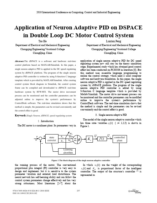
Application of Neuron Adaptive PID on DSPACE in Double Loop DC Motor Control SystemTao HeDepartment of Electrical and Mechanical Engneering Chongqing Engineering V ocational CollegeChongQing, ChinaLuntian PengDepartment of Electrical and Mechanical Engneering Chongqing Engineering V ocational CollegeChongQing, ChinaAbstract:The dSPACE is a software and hardware real-time control platform based on MATLAB/Simulink. In this paper, a single neuron adaptive PID is applied in the DC speed regulating system by dSPACE platform. The program of the single neuron adaptive PID controller is written by using S-function C language template which is provided by MATLAB/Simulink. After creating control system block diagram in Simulink, the control system frame can be compiled and downloaded to dSPACE real-time hardware system by RTW/RTI. The motor drive movement process can be monitored and the controller parameters can be adjusted online to improve the system’s performance by ControlDesk software. The real-time simulation shows that the method is simple, the parameters can be revised conveniently and the control effect is good.Keywords:Single Neuron, dSP ACE, speed regulating systemĉ. IntroductionThe DC motor is a nonlinear plant. Its parameters vary in the running process of the motor. The conventional proportional plus integral (PI) controller is very easy to design and implement, but it is sensitive to the system parameter variation and external load disturbance. The neural network has self-learning ability and can follow the control system parameters change effectively and has very strong robustness. Most literatures [1-7] about the application of single neuron adaptive PID for DC speed regulating system now still stay on the theory simulation stage. Experimental study which has obtained good control effect has been conducted on PC80386 in literature [8]. But this method uses assemble language programming to realize the control strategy, which need a solid computer software and hardware foundation. In this paper, the single neuron adaptive PID is applied in the DC speed regulating system by dSPACE platform. The program of the single neuron adaptive PID controller is edited by using S-function C language template which is provided by Matlab/Simulink. The motor drive movement process can be monitored and the controller parameters can be modified online to improve the system’s performance by ControlDesk software. The real-time simulation shows that the method is simple and the parameters can be revised conveniently and the control effect is good.Ċ. Single neuron adaptive PIDThe model of the single neuron adaptive controller which has three state variables ( i= 1,2,3) is shown in Figure 1.)(kx iIn which are the weight of the corresponding and is proportional factor of the intelligent controller. The output of the structure’s controller)(kw i)(kx i u K[6] is represented asFigure 1 The block diagram of the single neuron adaptive controller2010 International Conference on Computing, Control and Industrial Engineering»»¼º««¬ª ¦31/)()(i i i ugW k w k x K f U , (1)where W is the Euclidean norm of the weight which is written as follows:2/1232221)]()()([||||k w k w k w W .The weight may be determined through the learning study rule which is expressed as follows: )()()1(k r k w k w i i i i K , (2)where i K is learning rate parameters, have different forms. According to DC speed regulating system characteristic, combining surveillance’s Widrow-Hoff rule with non- surveillance’s Hebb rule, is taken with the following form )(k r i )(k r i [3]:. (3))()()()(k x k u k e k r i g i In Figure 1, the state variables are chosen as follows:(4)¦ ki i e Tk x 11)()( (5))()(2k e k x Tk e k e k x )1()()(3, (6)where T is sampling period and is the k th time sampling deviation value. To guarantee the convergence of the single neuron adaptive learning algorithm and the control system robust, combining with formula (1)ˈthe following equation is chosen as:)(k e ¦31*)()()(j j i i k w k w k w . ˄7˅According eqns.1and 7, one can obtain . (8))()()(3*k x k w K k u i i u ¦1i )()(max11)(k u k u g ee U k u (9)Substituting eqn. 8 into eqn. 1:Eqns. 4-9 constitute the single neuron adaptive PID control strategy. Single neuron adaptive PID maintains not only the single neuron’s advantage but also the traditional PID controller’s characteristic. The PID mathematical formula’s difference equation is)]1()([)()()1()()(1)([)(11¦¦k e k e K j e K k e K Tk e k e T T j e T k e k k u kj D IP kj dip (10˅where is proportional coefficient, is integral coefficient and is differential coefficient.P K I K D K Expanding eqn. 8 and comparing with eqn. 10, the following formula can be obtained ¦ 31)()()(j j i uP k w k w K k K ˄11˅¦ 31)()()(j j i uI k w Tk w K k K ˄12˅¦31)()()(j j i uD k w Tk w K k K . ˄13˅From eqn. 11 to eqn. 13, the proportional, the integraland the differential coefficient is not a fixed value, but change with the weight change. This shows that single neuron adaptive PID has auto-adaptive characteristic.T on Figure 2 The diagram of single neuron adaptive PID for DC speed regulating systemċ. Experimental researchesThe control block diagrams of single neuron adaptive PID for DC speed regulating system is shown in Figure 2.It is clear that the system has two controllers. In order to enhance the system robustness and reduce the speed overshoot, single neuron adaptive PID is used as speed regulator. The conventional PI regulator is adopted as the current regulator (ACR) to satisfy the system rapid response request. In this experiment the motor used is a DJ15 separately excited DC motor. The technical data are rated current : 1.2AN I rated running speed : 1600r/minN n rated voltage : 220V rated capacity : 185W excitation current <0.13AN U N P fN I excitation voltage : 220V .f U Through measuring and calculating, the following results can be obtainedarmature total resistance : 30.06¡ R armature total inductance : 532mH L flywheel inertia : 0.514N·m 2GD 2amplification factor of thyristor device :15 s K From these data the constants are determined as: electromotive force constant r V C e min/.121.0:torque coefficient A m N C m /.156.1:electromagnetism time-constant s T l 018.0:mechanical and electric time-constant s T m 25.0:current feedback coefficient AV /8.4:E speed feedback coefficient min//0035.0:r V D In this paper, dSPACE single board system DS1103 is used. The system has 20 groups A/D and 8 groups D/Achannel and can be connected with the computer by computer motherboard’s ISA slot. So signal connection may be carried conveniently. Figure 3 has given the hardware architecture diagram which includes the sPACE hardware platform, industrial control computer, the current and speed examination device, the rectifier device and the direct current motor and so on. All of them industrial control computer is the floor tool, the dSPACE hardware installs on its ISA slot and dSPACE software andMathWorks corporation’s MATLAB/Simulink also installs on the industrial control computer. In order to realize the single neuron adaptive PID controller, C language is used to edit the S-function. The demand contents are added into the C language template provided by MATLAB/Simulink. After compiling the S-function by using the command “mex” provided by MATLAB/Simulink, the same name S-function with a file type of “dll” is produced. Thus the S-function may use the standard module to express. TheSimulink control system diagram of DC speed regulatingsystem using the single neuron adaptive PID is shown in Figure 4.The module chart can be compiled and downloaded toFigure 4 The Simulink control system module diagram system diagramFigure 3 The architecture diagrams of dSPACE simulation platform for double loop DC speed regulator systemc u r r e n t /Atime/ss p e e d /r /m i nFigure 5 The current response curvedSPACE hardware by the expanded “RTW” of dSPACE. Using the integrated automatic experiment software ControlDesk can conveniently obtain the current and speed response curve as shown in Figure 5 and 6 respectively.Figure 5 expresses the current response curve when the motor starts with light-load and the load is added in t =9.3s. In the experiment, because of lower starting, the time of current maintaining the maximum value is very short. After the speed turns stable, the current also stabilizes basically. Figure 6 is the speed response curve. From the simulated result shown, the single neuron control system can confront the influence of parameter variations and external disturbance effectively and the speed overshoot is small when motor starting. This is mainly because the single neuron PID controller has differential action which can withdraw saturation in advance. According to Figure 6 the following control index can be obtained: overshoot of speed response ,speed maximum dynamic descent time ,s t m 38.0 speed recovery time .s t v 27.3 Č. ConclusionIn this paper, the single neuron adaptive PID is applied in the DC speed regulating system by dSPACE platform. The program of the single neuron adaptive PID controller is compiled by using S-function C language template which is provided by Matlab/Simulink. After creating control system structure in Simulink and compiling, the motor drive movement process can be monitored and the controller parameters can be adjusted online to improve the system’s performance with ControlDesk software. Thereal-time simulation shows that the method is simple and the parameters can be revised conveniently. The experiment results indicate that this control system can reduce the speed overshoot and the control effect is good.R EFERENCES[1]Wang Jing, Chen Hui (1999). “Application of Diagonal RecurrentNeural Network in Direct Current Dual Closed Loop Speed System”. Electric Drive , No. 4, pp. 25-28.[2]Xiang Yunwei (1999). “Self-adaptive Control Based on NeuralNetworks and PID for Direct Current Governor System”. Mechanical & Electrical Engineer Magazine , V ol. 16, No. 6, pp. 37 - 39.[3]Spool J T, MaggioreM, Ordonez R, et al. “Stable and Adaptive Controland Estimation for Nonlinear Systems: Neural and Fuzzy Approximator Techniques ”. Wiley Interscience, USA, 2002.[4]Ge S S. “Stable Adaptive Neural Network Contro l”. Kluwer AcademicPublishers, Dutch ,2002.[5]Lewis F L, Jagannathan S, Yesildirek A. “Neural Network Control ofRobot Manipulators and Nonlinear Systems ”. Taylor&Francis, Philaphia, 2003.[6]Liang Yu,Wang Dunsheng, Chen Jiaxing, et al (2007). “SimulationResearch of DC Adjusting Speed System Based on Neuron PID”. Coal Mine Machinery , V ol. 28, No. 6, pp. 53-55.[7]Yan Wei, Wang Tucai, Sun Xitong(2007). “Research on ControlStrategy of BLDCM Based on Single-neutron Adaptive PID Controllers”. Micro motors Servo Technique , V ol. 40, No. 8, pp.34-37. [8]Wang Xiaodong, Chen Boshi, Xia Chengguang (1996). “Realization ofintelligent adaptive control based on single neuron for DC drive system”. Electric Drive for Locomotive , V ol. 5, No. 10, pp. 12-15.Figure 6 The speed response curvetime/s。
外文翻译---双闭环直流调速系统的说明
外文翻译---双闭环直流调速系统的说明of motor used.2.SynthesisThe double loop DC speed control system consists of two closed loops: a speed loop and a current loop。
The speed loop is___ the motor speed。
while the current loop is ___ the motor current。
The system can be adjusted by changing the value of the feedback coefficient and the given value of the speed and current。
It is ___ factor of the power electronic ___.Ⅱ。
System components and their nsThe double loop DC speed control system is composed of several components。
including the motor。
the power electronic converter。
the speed sensor。
the current sensor。
the speed regulator。
and the current regulator。
Each component has a specific n in the system.The motor is the main component of the system and is ___ the DC voltage into an AC voltage to power the motor。
The speed sensor and current sensor are used to measure the motor speed and current。
双闭环直流调速系统的设计与仿真毕业设计论文
本科毕业设计(论文)题目:双闭环直流调速系统的设计与仿真研究Graduation Design (Thesis)Design and Simulation of Double Loop DC Motor Control SystemByWu JieSupervised byAssociate Prof. Zhang zhenyanDepartment of Automation EngineeringNanjing Institute of TechnologyMay, 2014摘要为了提高运动控制系统在实际工程中的应用效率,本文介绍了直流调速系统的工程设计方法[1],利用 MATLAB软件,对直流调速系统进行数学建模和系统仿真的研究。
所给出的仿真方法,可以灵活地调节系统的参数,从而获得理想的设计结果,并对设计出的系统进行分析。
建立调节器工程设计方法所遵循的原则是:1)概念清楚、易懂。
2)计算公式简明、好记。
3)不仅给出参数计算公式,而且指明参数调节方向。
4)能考虑饱和非线性控制的情况,同时给出简单的计算公式。
5)适合于各种可以简化成典型系统的反馈控制系统[2]。
由于这个课题相对简单,我在里面加入了相关性的内容以丰富本课题的广度和深度。
在本设计中,我加入了三种简单的单闭环直流调速系统,并且通过对它们进行仿真分析,比较找出了它们的不足之处,从而更明显地体现了双闭环直流调速系统的优越性。
并且通过对两种典型的双闭环直流调速系统进行仿真分析,从而更好地理解和运用双闭环直流调速系统[3]。
关键词:直流电动机;双闭环调速;MATLAB;仿真;直流调速系统;直流脉宽调制;工程设计方法ABSTRACTIn order to raise application efficiency of the motion control system in actual project ,this article discussed the engineering design methods of the speed-governing system of DC motor. The mathematical modeling and system simulation of direct current governor system are researched by means of MATLAB platform . The simulation method can adjust the system controller parameters flexibly, so as to achieve the ideal design results, and the design of the system are analyzed.A controller design method is the principles of:(1)The concept of clear, easy to understand.(2)Simple formula, easy to remember.(3)Not only gives the parameter calculation formula, and indicates the parameter adjustment direction.(4)Can consider the saturation nonlinear control, and gives a simple formula.(5)Suitable for all kinds of feedback control systems can be simplified into a typical system.Because this subject is relatively simple, I joined the correlation content inside to enrich the breadth and depth of the subject. In this design, I added three simple single loop DC speed regulation system, and then analyze them, compared to find their deficiencies, and thus more clearly showed the superiority of double closed loop DC speed regulating system. And through the simulation analysis of two kinds of typical double loop DC speed control system, so as to better understand and use the double loop DC speed control system.Keywords: DC motor, double closed loop,MATLAB,Simulation,V-M,PWM-M,The engineering design method目录摘要 (I)ABSTRACT (II)第一章绪论 (1)1.1 课题研究背景 (1)1.2 直流调速系统国内外研究现状 (1)1.3 研究双闭环直流调速系统的意义 (2)1.4 论文的主要研究内容 (2)第二章仿真软件以及相关硬件简介 (3)2.1 MATLAB/Simulink仿真平台 (3)2.2 仿真的数值算法 (3)2.3 工程设计法 (4)2.4 直流电动机 (4)第三章简单闭环调速系统的设计与仿真 (5)3.1 单闭环有静差转速负反馈调速系统的设计与仿真 (5)3.2 单闭环无静差转速负反馈调速系统的设计与仿真 (11)3.3 带电流截止负反馈的转速反馈系统的设计与仿真 (13)3.4 简单闭环调速系统的优缺点比较 (15)第四章转速、电流双闭环直流调速系统的设计与仿真 (17)4.1 转速、电流双闭环调速系统的设计与仿真 (17)4.2 V-M直流调速系统的设计与仿真 (19)4.3 PWM-M直流调速系统的设计与仿真 (26)第五章总结与展望 (34)致谢 (35)参考文献 (36)第一章绪论1.1 课题研究背景在现代化的工业生产过程中,许多生产机械要求在一定的范围内进行速度的平滑调节,并且要求有良好的稳态、动态性能[4]。
- 1、下载文档前请自行甄别文档内容的完整性,平台不提供额外的编辑、内容补充、找答案等附加服务。
- 2、"仅部分预览"的文档,不可在线预览部分如存在完整性等问题,可反馈申请退款(可完整预览的文档不适用该条件!)。
- 3、如文档侵犯您的权益,请联系客服反馈,我们会尽快为您处理(人工客服工作时间:9:00-18:30)。
对直流电机的速度闭环控制系统的设计
钟国梁
机械与汽车工程学院华南理工大学
中国,广州510640
电子邮件:zhgl2chl@
机械与汽车工程学院
华南理工大学
中国,广州510640
江梁中
电子邮件:jianglzh88@
该研究是由广州市科技攻关项目赞助(No.2004A10403006)。
(赞助信息)
摘要
本文介绍了直流电机的速度控制原理,阐述了速度控制PIC16F877单片机作为主控元件,利用捕捉模块的特点,比较模块和在PIC16F877单片机模数转换模块将触发电路,并给出了程序流程图。
系统具有许多优点,包括简单的结构,与主电路同步,稳定的移相和足够的移相范围,10000步控制的角度,对电动机的无级平滑控制,陡脉冲前沿,足够的振幅值,设定脉冲宽度,良好的稳定性和抗干扰性,并且成本低廉,这速度控制具有很好的实用价值,系统可以容易地实现。
关键词:单片机,直流电机的速度控制,控制电路,PI控制算法
1.简介
电力电子技术的迅速发展使直流电机的转速控制逐步从模拟转向数字,目前,广泛采用晶闸管直流调速传动系统设备(如可控硅晶闸管,SCR )在电力拖动控制系统对电机供电已经取代了笨重的F-D 发电机电动机系统,尤其是单片机技术的应用使速度控制直流电机技术进入一个新阶段。
在直流调速系统中,有许多各种各样的控制电路。
单片机具有高性能,体积小,速度快,优点很多,价格便宜和可靠的稳定性,广泛的应用和强劲的流通,它可以提高控制能力和履行的要求实时控制(快速反应)。
控制电路采用模拟或数字电路可以实现单片机。
在本文中,我们将介绍一种基于单片机PIC16F877单片机的直流电机速度控制系统的分类。
2.直流电机的调速原理
在图1中,电枢电压a U ,电枢电流a I ,电枢回路总电阻a R ,电机
常数a C 和励磁磁通Φ,根据KVL 方程,电机的转速为
Φ
-=a a a a C R I U n a
pN C 60= a a a a U R I U ≈-
)1(63.0)(84.0)1()1()()1()(10--+-=--+-=k e k e k T k e a k e a k T k T d d d
d i l T T Tf Kp
a T T Kp a +==+
=10)1(
图1 直流电机调速原理图
这里,p 是极对数,N 是圈数,a 为电机电枢支路数,电机常数是a pN C a 60=,这意味着当电机被证实,该值是固定的。
但是当a a a R I U -,只有绕组电阻a R ,所以a a R I 非常小。
所以很明显,当我们改变电枢电
压,转速n 随之变化。
3.系统的组成和工作原理
3.1系统硬件模块框架
系统的硬件模块框图如图2所示。
图2 系统硬件模块框图
3.2系统工作原理
该系统主要由主开关,电机励磁电路,晶闸管调速控制电路(包括转速表电路),整流滤波电路,平波电抗器放电电路,能耗制动电路,整个系统采用闭环PI调节器控制的实现。
当主开关闭合,这单相交流获得小的脉冲持续电流通过晶闸管调速控制电路的控制,和整流桥,为电机的滤波及平波电抗器,并在同一时间,通过整流励磁电路,交流使电机获得激励去开始工作。
在调节触发电路的速度设置电位器RP1由PIC16F877减少时,AN1输入电压下降使输出控制的角度,和晶闸管随流角,和主电路提高输出电压,和电机转速增加,增大和测速电路的输出电压,和电机稳定运行在设定的速度范围通过PI调节器的功能。
4.在系统各部分电路的设计
4.1主电路的设计
对电路中的各种成分的参数设置,如图3所示。
按下启动按钮开关SW,使接触器KM和KM回路,常开触点闭合,其常闭触点打开,并启动按钮自锁,主电路连接,与晶闸管调速电路通过改变双向晶闸管的控制角控制的交流输出,并通过桥梁得到直流整流和滤波,同时,电机通过整流励磁电路获得激励开始工作。
图3 主电路图设计
限制直流脉动,在电路中连接平波电抗器,和电阻R3提供放电回路平波电抗器在主电路突然断了。
加快制动,能耗制动是采用的设备,和制动部分由电阻R4和主电路接触器的常闭触点。
电动机的励磁是由单一的整流电路供电,并防止无法控制的高速事故通过电机的励磁损耗引起的,在激励电路中,串联电流继电器KA,和动作电流可以通过调节电位器RP。
4.2晶闸管触发电路的设计
图4 晶闸管触发电路设计
在主电路中的A点和B点的电压变为20V通过变压器,然后整流,约100小时半的信号发生在这两个点,并与NPN三极管通过信号分压R6和R7的放大,在三极管集电极产生过零脉冲,并捕获零通道脉冲上升沿的CCP1模块和注意发生第一时间,赶过零脉冲下降的边缘,和两者之间的时间差为零的脉冲宽度,和值的一半是中点的脉冲,通过捕捉模式,我们可以准确地获得实际的过零点的交流,并在同时,我们可以利用ADC的模拟/数字转换模块将PIC16F877引脚的模拟电压RA1 / AN1所设定的晶闸管控制的角度值(设定电机的转速值),改变设定值电位器RP1和相应地改变设置的晶闸管控制角的值,并输出值转速表电路由销RA1/AN1 PIC16F877的输入,和值作为速度反馈值通过A/D转换。
在单片机系统的振荡频率为4MHz,并根据特征PIC16F877订货周期,晶闸管控制角的分辨率是四分之一单片机振荡
的倒数1μ的频率,即,在电力10ms 的半波时间,控制角可以达到10000的步骤,完全实现电动机的无级平滑控制。
4.3测速电路设计
转速表电路由光学编码盘吸积与电机转子和电脉冲放大整形电路。
电脉冲频率固定的比例与电动机的转速,和通过放大整形,由光学码盘输出电脉冲从引脚RC0 /T1CK1输入PIC16F877作为标准的TTL 电平,由计数TMR1计数器计算转速,并比较与预设转速和转速得到差值,与PIC16F877单片机实现PI 操作这种差异的价值得到增加的控制,并将晶闸管的控制角来改变有效CCP2电机的两个端口的电压,从而控制转速。
5.软件设计
获得的晶闸管控制角较小的超调,我们设计的速度闭环控制系统作为典型的I 系统,即PI 调节器,这是用来调节晶闸管的控制角的时间d T ,其控制算法是
)1(63.0)(84.0)1()1()()1()(10--+-=--+-=k e k e k T k e a k e a k T k T d d d
)1(0i
l T T Kp a += 这里Kp a =1,p K 是比例系数,l T 是积分时间常数,i T 是采样周期。
考虑到系统中的电动机的电动机常数时间0.12s ,偏差不能被淘汰几种采样周期,所以我们选择采样周期2ms 的测速系统。
在系统软件设计模块主要包括CCP1上升捕获模块,CCP1降捕获模块,控制角度设定值的A/D 转换模块,转速表电路脉冲定时计数模
块,PI 调节器模块和CCP2比较输出模块的程序流程图,如图5和图6所示。
图5 PI 调节器模块框图
假设我们获得过零时间T ,与晶闸管控制角的时间d T ,因此,比
较值是发送到CCP2寄存器CCP2H:L 是d T T Tf +=,而当比较是一致的,
在该引脚输出高电平CCP2使晶闸管的连接,和修改CCP2H :L 的值再
根据需要的触发脉冲宽度值维持高电平输出触发脉冲一定时间后,再回到低的水平,所以双向晶闸管的触发脉冲输出已完成。
图6 CCP2比较输出模块
6.结论
速度控制系统以PIC16F877单片机为双向晶闸管触发电路的设计的文章具有许多特点是结构简单,运行可靠,调节范围宽,良好的电流的连续性和在中小型快速响应大小的直流电机速度控制系统,和旋
转速度环采用PI控制算法,能有效地抑制超调的转速,所以它是采用一种可行的设计单片机速度控制系统的运行曲线,如图7所示。
图7 速度控制系统运行曲线
工具书类
康华光、邹守彬(2000)电子技术基础:数字部分(第四版)。
北京:高等教育出版社
李学海(2002)PIC单片机实用教程。
北京:航空航天出版社北京大学
苏建(2002)对光伏水泵系统及其控制的研究。
合肥的博士学位论文科技大学张沈(1996)无刷直流电动机的原理和应用。
北京:机械工业出版社。