TLP平台安装实例
安装指南:kinetix tlp 电机电缆 2090-in048_-zh-p.pdf说明书
安装指南自制 Kinetix TLP 电机电缆目录号 2090-KTPC-MA-AA、2090-KTPC-MA-AE、2090-KTFB-MA-AA、2090-KTFB-MA-AE、2090-KTBK-MB-AA、2090-KTBK-MB-AE、2090-KTFB-MF-AA、2090-KTFB-MF-AE、2090-KTPC-MC-AA、2090-KTPC-MC-AE、2090-KTPC-MD-AA、2090-KTPC-MD-AE、2090-KTPC-ME-AA 和 2090-KTPC-ME-AE关于 Kinetix TLP 电机和电缆的组合以及 Kinetix TLP 电机电源和反馈电缆的规格,请参阅 Kinetix Motion Accessories Specifications Technical Data,出版号:KNX-TD004。
变更摘要本⼿册中包含新增和更新信息,如下表所述。
准备事宜拆除货品内外的所有包装材料。
拆除包装后,对照订购单确认产品目录号是否正确,并目视检查各连接器是否有损坏。
如有任何运输损坏,请立即通知承运商。
主题⻚码准备事宜1接线连接器2矩形连接器3军用型连接器8目录号说明13其他资源13主题⻚码为 Kinetix 5100 和 Kinetix 5300 伺服驱动器添加了电机/电源和制动器电缆散头引线剥⽪长度。
9添加了 Kinetix TLP 伺服电机的 400 V 级目录号。
13注意:为避免电击危险,确保屏蔽电源电缆至少有一个点接地。
为防止电能积聚,工厂提供的电源电缆使用下列接地技术之一:•整体屏蔽层搭接在连接器壳体上。
•露出一段整体屏蔽层,以便进⾏接地连接。
•整体屏蔽层连接到接地线。
如果存在裸露的电缆编织层或接地线,则将其连接到电源电缆夹、壳体或驱动器上其他相应的框架接地点。
重要事项选择散装电缆时必须考虑以下因素。
•电源电缆的额定电压必须高于所有工作条件下的系统电压。
海洋油井平台概述

各类海洋油井平台概述海洋石油钻采设备是海上油气田钻井与采油所用的工具和装备,它的种类繁多包罗万象,但归纳起来大体可以分为四类:1.海洋石油钻井平台;2.海洋石油采油平台;3.水上钻井机械设备;4.水下钻井机械设备。
本文主要介绍前两类,即:海洋石油钻井平台及海洋石油采油平台。
主要分为移动式平台和固定式平台两大类。
其中按结构又可分为:(1)移动式平台:坐底式平台、自升式平台、钻井船、半潜式平台(SEMI)、张力腿式平台(TLP)、牵索塔式平台、浮式生产处理系统(FPSO)、筒状平台(SPAR)。
(2)固定式平台:导管架式平台、混凝土重力式平台、深水顺应塔式平台。
移动式平台坐底式钻井平台坐底式钻井平台又叫钻驳或插桩钻驳,适用于河流和海湾等30米以下的浅水域。
坐底式平台有两个船体,上船体又叫工作甲板,安置生活舱室和设备,通过尾郡开口借助悬臂结构钻井;下部是沉垫,其主要功能是压载以及海底支撑作用,用作钻井的基础。
两个船体间由支撑结构相连。
这种钻井装置在到达作业地点后往沉垫内注水,使其着底。
因此从稳性和结构方面看,作业水深不但有限,而且也受到海底基础(平坦及坚实程度)的制约。
所以这种平台发展缓慢。
然而我国渤海沿岸的胜利油田、大港油田和辽河油田等向海中延伸的浅海海域,潮差大而海底坡度小,对于开发这类浅海区域的石油资源,坐底式平台仍有较大的发展前途。
目前已有几座坐底式平台用于极区,它可加压载坐于海底,然后在平台中央填砂石以防止平台滑移,完成钻井后可排出压载起浮,并移至另一井位。
自升式钻井平台自升式钻井平台被设计成为驳船的模样,具有可以升降的可延伸到海底的桩腿。
虽然有些设计能使其在海深500英尺(152米)的海域工作,但通常用于海深400英尺(122米)的地方,适合于近海。
其移位时平台降至水面,桩腿升起,平台就像驳船,可由拖轮把它拖移到目的地。
到达钻井目的地后,工作时桩腿下放插入海底,平台及平台上所有的钻井设备及其他器械被抬起到离开海面的安全工作高度,并对桩腿进行预压,以保证平台遇到风暴时桩腿不致下陷。
张力腿平台

张力腿平台发展与简介导管架平台和重力平台由于其自重和工程造价随水深大幅度地增加, 已经不适应深水域油气开发, 所以本世纪60 年代提出了顺应式平台的概念, 并在近20年的平台设计中得到了广泛的发展应用。
顺应式结构的典型实例是张力腿平台(Tension LegPlatform 简称为TLP)。
张力腿平台最重要的特点是平台的竖向运动很小, 水平方向的运动是顺应式的, 结构惯性力主要是水平方向的回弹力。
张力腿平台的结构造价一般不会随水深增加而大幅度地增大。
近二十年来, 经过张力腿平台设计生产的实践,证明张力腿平台具有良好的运动性能, 是深水海域油气生产适宜的平台形式。
张力腿平台结构张力腿平台(简称TLP)适用于较深水域(300~1500m)、且可采油气储量较大的油田。
TLP 一般由上部模块(Topside)、甲板、船体(下沉箱)、张力钢索及锚系、底基等几部分组成。
其船体(下沉箱)可以是三、四或多组沉箱,下设3~6组或多组张力钢索,垂直与海底锚定。
平台及其下部沉箱受海水浮力,使张力钢索始终处于张紧状态,故在钻井或采油作业时,TLP几乎没有升沉运动和平移运动。
其微小的升沉和平移运动(平移运动仅为水深的1.5% ~2%),在钻井和完井时主要由水中和井内相对细长的钻具及专用短行程补偿器补偿张力腿平台技术特点张力腿式钻井平台是利用绷紧状态下的锚索产生的拉力与平台的剩余浮力相平衡的钻井平台或生产平台。
张力腿式钻井平台也是采用锚泊定位的,但与一般半潜式平台不同。
其所用锚索绷紧成直线,不是悬垂曲线,钢索的下端与水底不是相切的,而是几乎垂直的。
用的是桩锚(即打入水底的桩为锚)或重力式锚(重块)等,不是一般容易起放的抓锚。
张力腿式平台的重力小于浮力,所相差的力量可依靠锚索向下的拉力来补偿,而且此拉力应大于由波浪产生的力,使锚索上经常有向下的拉力,起着绷紧平台的作用。
作用于张力腿式钻井平台上的各种力并不是稳定不变的。
在重力方面会因载荷与压载水的改变而变化;浮力方面会因波浪峰谷的变化而增减;扰动力方面因风浪的扰动会在垂向与水平方向产生周期变化,所以张力腿的设计,必须周密考虑不同的载荷与海况。
深水浮式平台的类型
深水浮式平台的类型深海有着强大的油气资源储备。
不断涌现的各种新型采油平台技术促进着深海采油技术的高速发展,这些技术概括起来可分为四大类:张力腿式平台(TLP),单筒式平台(SPAR),半潜式平台(SEMI)和浮(船)式生产平台(FPSO)。
在每一大类中,又有很多不同的技术概念。
下面就不同型式的平台使用和特点分别做介绍。
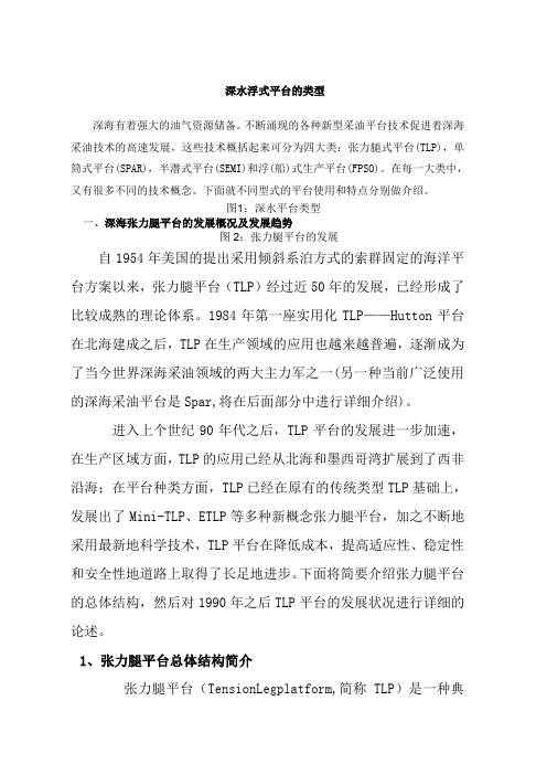
图1:深水平台类型一、深海张力腿平台的发展概况及发展趋势图2:张力腿平台的发展自1954年美国的提出采用倾斜系泊方式的索群固定的海洋平台方案以来,张力腿平台(TLP)经过近50年的发展,已经形成了比较成熟的理论体系。
1984年第一座实用化TLP——Hutton平台在北海建成之后,TLP在生产领域的应用也越来越普遍,逐渐成为了当今世界深海采油领域的两大主力军之一(另一种当前广泛使用的深海采油平台是Spar,将在后面部分中进行详细介绍)。
进入上个世纪90年代之后,TLP平台的发展进一步加速,在生产区域方面,TLP的应用已经从北海和墨西哥湾扩展到了西非沿海;在平台种类方面,TLP已经在原有的传统类型TLP基础上,发展出了Mini-TLP、ETLP等多种新概念张力腿平台,加之不断地采用最新地科学技术,TLP平台在降低成本,提高适应性、稳定性和安全性地道路上取得了长足地进步。
下面将简要介绍张力腿平台的总体结构,然后对1990年之后TLP平台的发展状况进行详细的论述。
1、张力腿平台总体结构简介张力腿平台(TensionLegplatform,简称TLP)是一种典型的顺应式平台,通过数条张力腿与海底相连。
张力腿平台的张力筋腱中具有很大的预张力,这种预张力是由平台本体的剩余浮力提供的。
在这种以预张力形式出现的剩余浮力作用下,张力腿时刻处于受预拉的绷紧状态,从而使得平台本体在平面外的运动(横摇、纵摇、垂荡)近于刚性,而平面内的运动(横荡、纵荡、首摇)则显示出柔性,环境载荷可以通过平面内运动的惯性力而不是结构内力来平衡。
张力腿平台简介
张力腿平台简介一.第一代张力腿平台总述第一代张力腿平台,即传统类型的张力腿平台,应用时间长、分布范围广、平台数量多、设计理论成熟,在张力腿平台发展的历史中占有很重要的地位。
从1984年至今,世界上建成投入生产的传统类型张力腿平台共有11座,尚未发生过倾覆、沉没等重大事故,拥有优良的工作记录,由此坚定了业界对TLP这种新兴海洋平台结构的信心。
在其发展的20年时间里,世界各国的研究者和工程技术人员积累了丰富的设计应用经验和技术数据,为以后张力腿平台的发展打下了坚实的基础。
在已建成的11座传统类型的张力腿平台中,Shell石油公司在1994—2001年7年间连续建造的5座张力腿平台具有一定的代表性,分别为Auger、Mars、Ram、Ursa和Brutus。
通过第一代张力腿平台的生产实践,进一步证明了张力腿平台在深海域半刚性半柔性的优良运动性能和经济性,但是同时亦发现传统的张力腿平台结构形式仍存在着一定的不足。
①在水深超过1200m的极深水水域,随着张力筋腱长度的增加,出现了张力腿自重过大的问题,并且由于张力筋腱在深水中的受力情况发生改变,因此影响了平台的定位性能。
②在降低造价、改善受力情况和运动性能的方面,传统类型张力腿平台的本体结构仍需要进一步改进。
③差频载荷是一个缓慢变化的力,它将和同样缓慢变化的张力腿平台平面内的运动发生共振。
另外,风的激振力也在这个差频范围内,必然会加剧这种慢漂运动。
④波浪的高频分量和高频水动力会引起张力腿平台平面外的共振,通常称为Springing和Ringing。
张力腿平台结构这两个问题随着水深的增加而加剧,对结构的安全性有很大的影响。
⑤传统的张力腿平台是通过海底基础固定入位的,随着水深的增加,海底基础的设计、施工变得十分复杂。
因此,张力腿平台所具有的经济、安全和良好的动力特性在更深水域中均不能得到充分的发挥,传统类型的张力腿平台结构已经不能很好地适应更深的水域。
各国学者对张力腿平台结构形式的不断改进完善非常重视,因此,混合式张力腿平台及悬式张力腿平台等新型的张力腿平台便应运而生二.张力腿平台的工作原理及性能张力腿平台设计最主要的思想是使平台半顺应半刚性。
张力腿平台

MOSES TLP的主体由四 根细长角柱和一个水下浮式 基座构成。平台的浮力主要 由水下浮式基座提供。
ETLP
9
按采油树位置分类
湿树平台 采油树位于海底。减少了平台上体的负载,不需要建造体 积庞大的平台主体,因而降低了平台的总体造价,湿树平台的 生产储备能力具有很大的弹性,新增的设备和海底油井容易加 装到现有的生产系统中,对油田的远期开发比较方便。
5
建造与安装过程
张力腿平台通常是将平台主体和上体分开建造,然后在海上进行合拢。
SeaStar TLP的整个安装过程可以分为4个独立的阶段进行。每个阶段耗时 都较短,并且当每个安装阶段结束后.己完成安装的平台部分都处于风暴 安全状态.可以最大程度地缩短平台处于不稳定状态中的时间,降低了作 业风险。
7
第一代张力腿平台
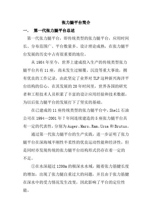
Heidrun TLP建成于1995年,位 于北海距挪威海岸175km的海域,工 作水深345m。 Heidrun TLP是世界上第一座也 是惟一的一座混凝土张力腿平台。因为 其主体构造采用了混凝土结构,所以主 体排水量远远超过其他钢制张力腿平台, 达到了288000t左右。 从1984年至今,世界上建成投入 生产的传统类型张力腿平台共有11座, 尚未发生过倾覆、沉没等重大事故,拥 有优良的工作记录,由此坚定了业界对 TLP这种新兴海洋平台结构的信心。
张力腿平台通过自身的结构形式,产生远大于结构自重的 浮力,剩余部分称为剩余浮力。这部分剩余浮力与预张力 平衡。
半顺应半刚性:
预张力使张力腿时刻处于受张拉的绷紧状态,从而使平台 平面外的运动(横摇、纵摇和垂荡)较小,近似于刚性。 张力腿平台本体主要是直立浮筒结构,一般浮筒所受波浪 力的水平方向分力较垂直方向分力大,因而通过张力腿在 平面内的柔性,实现平台平面内的运动(纵荡、横荡和首 摇),即为顺应式。
spar平台
小平台是生产和生活的中心,一般分为二层或三层的模块结构,甲板形状为矩形。
各个甲板之间用立柱和斜撑结构连接固定。
平台主体顶部装有立柱基座,与主体的垂直防水壁形成一个整体,平台上体的主支撑立柱直接与立柱基座对接,并贯入主体内部以便达到较好的固定效果。
生产和生活设施基本上按照传统平台的甲板布局方式布置,根据设计要求,可在顶层甲板上安装重型或轻型钻塔,以完成平台钻探、完井和修井作业。
主体:1.Classic spar:是一个在水中垂直悬浮的圆柱体,整体直径较大,主体尺度一般都在100m以上,重心位于水线面以下很深的位置。
庞大的主体内部采用垂直隔水舱壁和水平甲板分隔成多层多舱结构,并具有各自的功能。
分为:硬舱、中段和软舱。
硬舱:主体顶甲板至可变压载舱底部之间的部分称为硬舱。
z硬舱位于主体的上部,是整个spar平台系统的主要浮力来源。
这部分中的舱室分为固定浮舱和可变压载舱。
z在靠近水线面处的浮舱外层还布置有双层防水壁结构,在平台撞击损坏时能够起到保护浮舱的屏障作用。
中段(midsection):可变压载舱底部至临时浮舱顶甲板之间的部分称为中段。
其功能是刚性连接spar平台主体硬舱和软舱,并且保护中央井中的立管系统不受海流力的影响。
z中段部分最主要的两个结构是外壳体和内壳体,外壳体位于主体的最外侧,负责保护主体内的舱室,贯穿整个中段部分,这就是平台的储油舱。
z另外,spar平台的系泊索与平台主体的连接点也位于中段,中段的主体外侧装有定滑轮结构的导缆器。
软舱(soft tanks)Spar平台主体在中段以下的部分称为软舱。
Spar平台的压载大部分由软舱提供。
软舱中的舱室分为固定压载舱和临时浮舱。
Truss spar桁架结构:z是一个类似于导管架(jacket)结构的空间钢架,同传统Spar的金属圆柱中部结构相比,可以节省50%的刚才。
z通常由无内倾立腿,水平撑杆,斜杆和垂荡板(Heave plate)组成。
桁架中的管状部件在整个Spar的使用过程中均产生浮力。
Extron TLP Pro 1022T 安装指南说明书

I M P O R T A NT:m f o rt h el l a t i o n .c oTLP Pro 1022T • Setup GuideOverviewThe TLP Pro 1022T is a 10-inch tabletop capacitive touchscreen with 1024x600 resolution and 18-bit color depth. It offers flexible mounting options and fully customizable interfaces. This guide provides instructions for experienced installers to mount and install a TLP Pro 1022T touchpanel. For complete instructions, see the TLP Pro 1022 Series User Guide, at . Setup ChecklistGet ReadyDownload and install the latest version of the following software:GUI Designer — for designing layouts for Extron TouchLink® Pro touchpanels and third party touch interfaces.Global Configurator® Professional or Global Configurator Plus — for setting up and configuring the control processor and touchpanel.Toolbelt — provides device discovery, device information, firmware updates, and configuration of network settings, system utilities, and user management for TouchLink Pro devices.All three software programs are available from .Obtain the following network information from your network administrator:DHCP status (on or off). If DHCP is off, you must also obtain:IP address Subnet mask GatewayUser name — this can be either admin or user.Password — by default this is extron (for either admin or user).Make a note of the touchpanel MAC address.Mount and Cable All DevicesMount the units. There are several mounting options for TouchLink Pro touchpanels (see Mounting on the following page).Connect the touchpanel to a Power over Ethernet injector.Connect the power injector to the LAN and power it on.Set up the Touchpanels for Network CommunicationConnect the PC that you are using for setup, the control processor, and touchpanel to the same Ethernet subnetwork.Use the Setup Menu (see page 4) or Toolbelt to set the DHCP status and, if necessary, the IP address, subnet mask, gateway, and related settings for the touchpanel.Configure the TouchpanelsThe GUI Designer Help File, the Global Configurator Help File, and the Toolbelt Help File provide step-by-step instructions and more detailed information. The Global Configurator Help File includes an introduction to the software and sections on how to starta project and configuration.1TLP Pro 1022T • Setup Guide (Continued)MountingThe TLP Pro 1022T comes with a stand that allows it to be placed on any suitable flat surface. See for a range of available optional mounting kits. The kits must be purchased separately. Follow the installation instructions provided with the kit.Removing the Base and Back CoversTo attach cables and to mount the TLP Pro 1022T with the SMA-1 or a VESA mounting kit, you must remove the base and back covers:1. Remove the base cover using the provided Extron removal tool.There is a notch at the back edge of the cover (see figure 1, 2).2. When the base cover is removed, a pull tab can be seen (seefigure 2). Use this to remove the back cover.Kensington® Security LockFor added security, attach a Kensington Security Lock (not provided) to the metal-reinforced slot on the rear edge of the base (see figure 1,1). Follow the instructions that are provided by the manufacturer toinstall the lock.Securing the Touchpanel to a Table1. Under the table top, mark the location of two mounting holes,3.07 inches (78 mm) apart (see figure 3, A).2. Drill two holes through the table top from underneath.3. Attach the touchpanel, using two #8 machine screws through thetable top from underneath into the two holes in the base.SMA-1 Swivel Mount AdapterThe TLP Pro 1022T can be mounted with the optional Extron SMA-1 swivel mount adapter, which allows it to be mounted permanently and swivel up to 180° in either direction.1. Remove the base and back covers as described in Removing theBase and Back Covers, above.2. Remove the screw holding the locking plate at the bottom of thebase (see figure 3, B). This releases the weight, which can beremoved from the top of the base, leaving the mounting hole thatwill fit over the conduit of the SMA-1.3. Attach the conduit, insulation disk, and swivel disk and configurethe set screws to allow for the degree of swivel that is required(see the SMA-1 Swivel Mount Adapter Kit User Guide, available at).4. Place the mounting hole in the base over the SMA-1 conduit.5. Secure the unit with the backing plate and locking nut asdescribed in the SMA-1 Swivel Mount Adapter Kit User Guide. VESA Mounting1. Remove the back cover, as described in Removing the Base andBack Covers, above.2. Remove the four screws holding the touchpanel to its base. Thereare two screws in each base attachment hinge (see figure 5, F).3. Use a D-type VESA mounting kit with 75 x 75 mm mountingpattern. Follow the instructions provided with the kit.12Figure 1. Rear of TLP Pro 1022T BasePull Tab(to RemoveBack Cover)Figure 2. TLP Pro 1022T with Base Cover RemovedAB Figure 3. TLP Pro 1022T Base2Front Panel FeaturesFigure 4. TLP Pro 1022T Front PanelA Communication LED — shows the configuration and connection status of the touchpanel:z Unlit during normal operation (the touchpanel is configured and connected to an IP Link Pro control processor).z Blinks red if the touchpanel has been configured but is not connected to an IP Link Pro control processor.z Continuously lit red if the touchpanel has not been configured.The indicator can be toggled between enabled and disabled, using the Setup Menu (see the following page).B Status lights — one LED light bar, above the screen, which can be programmed to provide system feedback.z Light red or greenz Blink or light continuouslyz For information about programming this light, see the Global Configurator Help File.C Light sensor — monitors ambient light level and adjusts screen brightness.D Capacitive touchscreen — 10.1-inch screen with 1024x600 resolution.E Speakers — two speakers, located below the screen, one on each side of the panel, provide audible feedback for the user.F Motion sensor — detects motion between three to five feet in front of the touchpanel, and at least 15° from the center axis.z When no motion has been detected for a user-defined period of time, the touchpanel enters sleep mode.z When motion is detected by the sensor, the screen display is restored and active.Rear Panel FeaturesFigure 5. TLP Pro 1022T Rear Panel A LAN/PoE (Power over Ethernet) ConnectorB VESA Mounting Holes (4)C Menu ButtonD Reset ButtonE Reset LEDF Base Attachment Hinges (2)3468-2405-53 Rev. A04 16Extron Headquarters+1.800.633.9876 (Inside USA/Canada Only)Extron USA - West Extron USA - East +1.714.491.1500 +1.919.850.1000+1.714.491.1517 FAX +1.919.850.1001 FAXExtron Europe+800.3987.6673 (Inside Europe Only)+31.33.453.4040+31.33.453.4050 FAXExtron Asia +65.6383.4400+65.6383.4664 FAX Extron Japan +81.3.3511.7655+81.3.3511.7656 FAX Extron China +86.21.3760.1568+86.21.3760.1566 FAX Extron Middle East +971.4.299.1800+971.4.299.1880 FAX Extron Australia +61.8.8351.2188+61.8.8351.2511 FAXExtron India 1800.3070.3777 (Inside India Only)+91.80.3055.3777+91.80.3055.3737 FAX© 2016 Extron Electronics All rights reserved. All trademarks mentioned are the property of their respective owners. TLP Pro 1022T • Setup Guide (Continued)A LAN/PoE (Power over Ethernet) Connector — is in the top of the recessed area (see figure 5, A on the previouspage). Connect the touchpanel to a PoE power injector (not provided) using a twisted pair cable, terminated with an RJ-45 connector. Connect the power injector to the LAN through a network switch. An Extron IP Link Pro control processor mustalso be connected to the same network as the TouchLink Pro touchpanel.The figure to the right shows the Extron XTP PI 100. Your power injector may look different.B VESA mounting holes (4) — If using VESA mounting, use a D-type VESA mountingkit with 75 x 75 mm mounting pattern (see VESA Mounting on page 2).C Menu button — activates the Setup Menu and calibration screen (see below).D Reset button — Pressing the Reset button allows the unit to be reset in any of three different modes. For full information about the modes, see the TLP Pro 1022 Series User Guide .E Reset LED — provides feedback about the reset status when the user presses the Reset button.F Base attachment hinges (2) — Each hinge secures the touchpanel to the base with two screws.Reset Modes: a Brief SummaryThe TLP Pro 1022T offers the following reset modes:• Use Factory Firmware:Press and hold the Reset button (figure 5, D ) while applying power to the unit. Use this mode with Global Configurator or Toolbelt software to replace firmware in the event of conflicts arising from uploading a firmware update.• Reset All IP Settings:Press and hold the Reset button for 6 seconds. After the Reset LED (figure 5, E ) flashes twice, release and momentarily press the Reset button. Use this mode to reset all network settings without affecting user-loaded files.• Reset to Factory Defaults:Press and hold the Reset button for 9 seconds. After the Reset LED flashes three times, release and momentarily press the Reset button. Use this mode to return the touchpanel to factory default settings.Setup MenuPress the Menu button (see figure 5, C ) to open the setup menu. Select any of the five available screens (Status , Network , Display , Audio , and Advanced ) by pressing the appropriate button in thenavigation bar at the top of the screen (for more information, see the TLP Pro 1022 Series User Guide ).Press and hold the Menu button for at least 3 seconds to open the calibration screen. Follow the on-screen instructions.Figure 6. Setup Menu: Status Screen for TLP Pro 1022TTo network switch To touchpanel。
- 1、下载文档前请自行甄别文档内容的完整性,平台不提供额外的编辑、内容补充、找答案等附加服务。
- 2、"仅部分预览"的文档,不可在线预览部分如存在完整性等问题,可反馈申请退款(可完整预览的文档不适用该条件!)。
- 3、如文档侵犯您的权益,请联系客服反馈,我们会尽快为您处理(人工客服工作时间:9:00-18:30)。
32
CNOOC Deepwater Seminar
张大刚 2006年9月21日-9月22日
33
CNOOC Deepwater Seminar
张大刚 2006年9月21日-9月22日
34
CNOOC Deepwater Seminar
张大刚 2006年9月21日-9月22日
35
CNOOC Deepwater Seminar
CNOOC Deepwater Seminar
张大刚 2006年9月21日-9月22日
16
CNOOC Deepwater Seminar
张大刚 2006年9月21日-9月22日
17
CNOOC Deepwater Seminar
张大刚 2006年9月21日-9月22日
18
CNOOC Deepwater Seminar
桩基打入深度变化 桩基偏位 张力腿安装中损坏 平台安装时的环境超出容许要求 平台稳性 主体和张力腿的锁住,连接
14
CNOOC Deepwater Seminar
张大刚 2006年9月21日-9月22日
Pile Transportation and Installation
15
9
CNOOC Deepwater Seminar
张大刚 2006年9月21日-9月22日
10
CNOOC Deepwater Seminar
张大刚 2006年9月21日-9月22日
11
CNOOC Deepwater Seminar
张大刚 2006年9月21日-9月22日
12
CNOOC Deepwater Seminar
22
CNOOC Deepwater Seminar
张大刚 2006年9月21日-9月22日
23
CNOOC Deepwater Seminar
张大刚 2006年9月21日-9月22日
24
CNOOC Deepwater Seminar
张大刚 2006年9月21日-9月22日
Tendon Transportation & Installation
5
CNOOC Deepwater Seminar
张大刚 2006年9月21日-9月22日
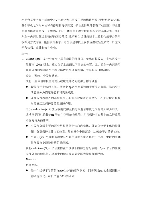
Topsides Fabrication
• • • • Project awarded on Oct. 15, 2004 AFC drawings issued on Dec. 31, 2005 Steel cutting started on Feb. 15, 2005 Topsides fabrication completed in December, 2005 • Topsides commissioning started in December 2005
Dec. 17, 2005 Dec. 20, 2005 Dec. 23, 2005 Dec. 25, 2005 Dec. 27, 2005 Dec. 27, 2005 Dec. 29, 2005 Dec. 29, 2005 Dec. 31, 2005 Dec. 31, 2005 Jan. 2, 2006 Jan. 4, 2006
张大刚 2006年9月21日-9月22日
张力腿平台安装主要过程
桩基自穿透 打桩 张力腿安装 张力腿临时浮筒安装 平台拖浮于安装位置 平台安装-张力腿锁住,减载,定位
13
CNOOC Deepwater Seminar
张大刚 2006年9月21日-9月22日
张力腿平台安装可能出现的问题
7
CNOOC Deepwater Seminar
张大刚 2006年9月21日-9月22日
8
CNOOC Deepwater Seminar
张大刚 2006年9月21日-9月22日
Operation Schedule
Okume Hull Weighing – Oveng Hull Weighing – Okume Topsides Weighing – Okume Hull Lifting – Okume Hull Rotation And Mooring – Okume Topsides Loadout – Okume Topsides Lifting & Integration – Oveng Topsides Weighing – Oveng Hull Lifting – Oveng Topsides Loadout – Oveng Hull Rotation and Mooring – Oveng Topsides Lifting & Integration –
CNOOC Deepwater Seminar
张大刚 2006年9月21日-9月22日
张力腿平台安装实例
Dagang Zhang
1
CNOOC Deepwater Seminar
张大刚 2006年9月21日-9月22日
Table of Contents
Project Introduction Platform Loadout, Transportation, and Integration Pile Transportation and Installation Tendon Transportation and Installation Platform Tow and Installation
Awarded on Oct. 2004 Installed on April 2006
3
CNOOC Deepwater Seminar
张大刚 2006年9月21日-9月22日
4
CNOOC Deepwater Seminar
张大刚 2006年9月21日-9月22日
Hull Fabrication
39
CNOOC Deepwater Seminar
张大刚 2006年9月21日-9月22日
Platform Tow and Installation
40
CNOOC Deepwater Seminar
张大刚 2006年9月21日-9月22日
Tendon Pull In
41
CNOOC Deepwater Seminar
张大刚 2006年9月21日-9月22日
Tendon Pull In
42
CNOOC Deepwater Seminar
张大刚 2006年9月21日-9月22日
43
CNOOC Deepwater Seminar
张大刚 2006年9月21日-9月22日
44
CNOOC Deepwater Seminar
2
CNOOC Deepwater Seminar
张大刚 2006年9月21日-9月22日
Introduction
Okume and Oveng: two identical TLPs First self-stable MOSES TLPs First TLPs in E.G. area First time two identical floating structures going side by side for project First two TLPs using the same tender assisted drilling vessel for the field development Industry milestone in floating structure execution Shortest floating system project schedule: less than 18 months
48
CNOOC Deepwater Seminar
张大刚 2006年9月21日-9月22日
49
CNOOC Deepwater Seminar
张大刚 2006年9月21日-9月22日
50
• • • • Project awarded on Oct. 15, 2004 AFC drawings issued on Dec. 15, 2004 Steel cutting started on Feb. 15, 2005 Hull fabrication completed in November, 2005 • Hull commissioning started in December 2005
张大刚 2006年9月21日-9月22日
29
CNOOC Deepwater Seminar
张大刚 2006年9月21日-9月22日
30
CNOOC Deepwater Seminar
张大刚 2006年9月21日-9月22日
31
CNOOC Deepwater Seminar
张大刚 2006年9月21日-9月22日
25
CNOOC Deepwater Seminar
张大刚 2006年9月21日-9月22日
26
CNOOC Deepwater Seminar
张大刚 2006年9月21日-9月22日
27
CNOOC Deepwater Seminar
张大刚 2006年9月21日-9月22日
28
CNOOC Deepwater Seminar
张大刚 2006年9月21日-9月22日
19
CNOOC Deepwater Seminar
张大刚 2006年9月21日-9月22日
20
CNOOC Deepwater Seminar
张大刚 2006年9月21日-9月22日