RCWP5100MKMTP中文资料
常用三极管参数大全
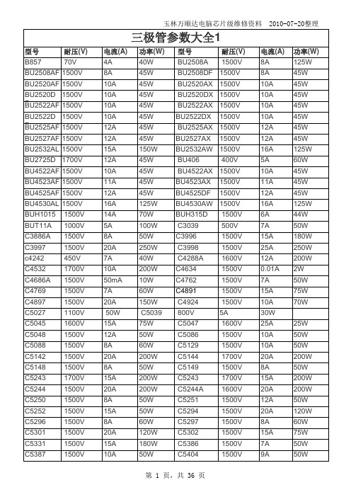
玉林万顺达电脑芯片级维修资料 2010-07-20整理玉林万顺达电脑芯片级维修资料 2010-07-20整理玉林万顺达电脑芯片级维修资料 2010-07-20整理玉林万顺达电脑芯片级维修资料 2010-07-20整理玉林万顺达电脑芯片级维修资料 2010-07-20整理玉林万顺达电脑芯片级维修资料 2010-07-20整理玉林万顺达电脑芯片级维修资料 2010-07-20整理玉林万顺达电脑芯片级维修资料 2010-07-20整理玉林万顺达电脑芯片级维修资料 2010-07-20整理玉林万顺达电脑芯片级维修资料 2010-07-20整理玉林万顺达电脑芯片级维修资料 2010-07-20整理玉林万顺达电脑芯片级维修资料 2010-07-20整理玉林万顺达电脑芯片级维修资料 2010-07-20整理玉林万顺达电脑芯片级维修资料 2010-07-20整理玉林万顺达电脑芯片级维修资料 2010-07-20整理玉林万顺达电脑芯片级维修资料 2010-07-20整理玉林万顺达电脑芯片级维修资料 2010-07-20整理玉林万顺达电脑芯片级维修资料 2010-07-20整理玉林万顺达电脑芯片级维修资料 2010-07-20整理玉林万顺达电脑芯片级维修资料 2010-07-20整理玉林万顺达电脑芯片级维修资料 2010-07-20整理玉林万顺达电脑芯片级维修资料 2010-07-20整理玉林万顺达电脑芯片级维修资料 2010-07-20整理玉林万顺达电脑芯片级维修资料 2010-07-20整理玉林万顺达电脑芯片级维修资料 2010-07-20整理玉林万顺达电脑芯片级维修资料 2010-07-20整理玉林万顺达电脑芯片级维修资料 2010-07-20整理玉林万顺达电脑芯片级维修资料 2010-07-20整理玉林万顺达电脑芯片级维修资料 2010-07-20整理玉林万顺达电脑芯片级维修资料 2010-07-20整理。
K-PW 系列电源配电板使用说明书
HOLLiAS MACS -K系列模块2014年5月B版HOLLiAS MAC-K系列手册- K-PW系列电源配电板使用说明书重要信息危险图标:表示存在风险,可能会导致人身伤害或设备损坏件。
警告图标:表示存在风险,可能会导致安全隐患。
提示图标:表示操作建议,例如,如何设定你的工程或者如何使用特定的功能。
目录1.概述 (1)2.K-PW01 交流电源配电板 (2)2.1连接器定义 (2)2.2外形尺寸 (3)3.K-PW11 直流电源配电板 (4)3.1连接器定义 (4)3.2外形尺寸 (7)4.K-PW21 查询电源分配板 (8)4.1连接器定义 (8)4.2指示灯 (9)4.3外形尺寸 (9)5.技术指标 (10)5.1K-PW01 (10)5.2K-PW11 (10)5.3K-PW21 (11)K-PW系列电源配电板1.概述K-PW系列电源分配板有三个型号,分别是K-PW01、K-PW11和K-PW21。
K-PW01是交流电源配电板,K-PW11是直流电源配电板,安装在机柜背面,配合AC/DC电源模块,为整个K系列硬件提供系统电源、现场电源。
K-PW21是查询电源分配板,安装在机柜正面,为I/O模块提供24V/48VDC查询电源。
下面将分别介绍。
2.K-PW01 交流电源配电板K-PW01是K系列硬件交流分配板,实现交流电源的分配输出功能,给系统电源、现场电源、辅助电源的AC/DC电源模块提供输入配电。
有两路110V/220V交流电输入,每路输入交流电源平分成5路输出。
两组通道各带有一个PCB安装滤波器,用来给系统电源和现场电源AC/DC供电。
每路带独立的船型开关,可以接通或关断本路,开关上自带通断指示灯。
船型开关在切断对应通道电源时,该指示灯熄灭;接通对应通道电源时,该指示灯亮。
K-PW01交流配电板安装在35mm宽的标准DIN导轨上,与导轨采用卡扣的固定方式,其外观示意图如图2-1所示。
PowerMark 静态激光打标机说明书

PowerMark静态激光打标机说明书目录1概述 (1)1.1软件简介 (1)1.2软件功能 (1)1.3界面描述 (1)2文件菜单 (2)2.1新建 (2)2.2打开 (3)2.3另存为 (4)2.4保存 (4)2.5导入/导出文档 (5)2.6导入/导出字体 (5)2.7导入/导出图片 (5)2.8导入/导出矢量图 (5)2.9导入/导出数据库 (5)2.10导入/导出打标记录 (5)3视图 (6)4编辑菜单 (7)4.1复制 (7)4.2粘贴 (7)4.3多重复制 (8)4.3.1矩形排列 (9)4.3.2圆形排列 (11)4.4相对复制 (12)4.5删除 (12)4.6撤销 (12)4.7重做 (13)4.8群组/分离群组 (13)4.9组合/分离组合 (13)4.10转为曲线 (14)4.11阵列 (14)4.12填充 (14)4.13变换 (16)4.14分布 (18)4.15排序 (19)4.16线条优化 (19)4.17创建多点 (20)4.18去除交叉点 (20)4.19等宽设定 (21)4.20等高设定 (21)4.21转为虚线 (21)4.22修剪 (21)4.23造形 (22)4.24偏移 (22)5工具栏 (23)5.1移动到中心 (23)5.2视图 (23)5.3登录 (23)5.4隐藏快速工具栏 (23)5.5帮助 (24)6设置菜单 (25)6.1激光校正 (26)6.2多点校正 (31)6.3红光校正 (32)6.4激光参数 (33)6.4.1光纤激光器 (33)6.4.2CO2激光器 (35)6.4.3YAG(紫外)激光器 (37)6.4.5SPI激光器 (44)6.4.6激光器状态提示 (45)6.5激光测试 (45)6.6IO配置 (46)6.6.1端口解释 (47)6.6.2输入端口说明 (47)6.6.3输出端口说明 (48)6.6.4调试IO口 (49)6.6.5DB15扩展IO口说明 (49)6.6.6CON5接线口说明 (51)6.7扩展轴参数配置 (51)6.8系统 (52)6.9串口 (55)6.9.1默认协议 (56)6.9.2字符流协议 (56)6.9.3调试模式 (56)6.10网络通讯 (56)6.10.1以太网 (57)6.10.2Wifi (57)6.10.3通讯协议 (57)6.10.4调试模式 (58)6.10.5网页服务 (58)6.11Modbus设置 (58)6.11.1网络 (58)6.11.2串口 (59)6.12打标高级设置 (59)6.13资源管理/升级 (60)6.14备份/还原 (61)6.14.2一键系统备份/还原 (61)6.15打标记录管理 (62)6.16权限 (62)6.17触摸校正 (63)6.18模块管理器 (63)6.19关于 (63)7扩展菜单 (64)7.1旋转轴 (65)7.2条码打印 (67)7.3一维平面拼接 (68)7.4字体编辑器 (69)7.5IC芯片打标 (69)7.6多文档打标 (69)7.7条码扫描验证 (71)7.8电路板打码&验码 (72)7.9激光清洗 (72)7.10笔号分组打标 (73)7.11简易主页 (74)7.12事件管理器 (74)7.13扩展轴调试 (75)7.14文件队列打标 (76)7.15多卡打标 (76)7.16二维分拆打标 (76)7.17通讯配置管理器 (77)7.18投影标刻 (77)7.19服务器缓存记录打标 (77)7.20WebServer设置 (78)8绘制和对象属性栏 (79)8.1点 (79)8.2直线 (79)8.3矩形 (80)8.4椭圆 (81)8.5曲线 (82)8.6多边形 (82)8.7矢量图 (83)8.8普通文本 (83)8.9组合文本 (85)8.9.1静态文本 (87)8.9.2时间 (87)8.9.3日期 (87)8.9.4扫描枪 (87)8.9.5序列号 (88)8.9.6数据库 (89)8.9.7换行符 (90)8.9.8挂接文本 (90)8.9.9随机码 (90)8.9.10串口通讯 (90)8.9.11网络通讯 (90)8.10图片 (90)8.11条形码/二维码 (91)8.12延时器 (94)8.13VIN码 (94)8.14螺旋线 (94)8.15焊接线 (95)8.16控制点 (95)8.17标尺 (96)9对象列表 (98)10笔号属性栏 (99)10.1笔号属性 (99)10.2参数管理器 (104)11打标控制栏 (106)12状态栏 (108)13输入法 (109)14工具 (110)14.1记事本 (110)14.2转码工具 (110)14.3计算器 (110)14.4端口占用查看器 (110)14.5快速属性编辑器 (110)14.6序列号生成数据库 (110)14.7加工计数器 (110)14.8串口调试助手 (111)14.9网络调试助手 (111)14.10IO口调试 (111)1概述1.1软件简介1.2软件功能1.3界面描述图1-12文件菜单文件菜单实现了常规的文档操作,包括新建、打开、另存为、保存和资源导入导出等。
MICOM-P520-电动机保护资料
!"#$%&'"#$()
!(
)
:90%
!"#$%&'
!"#$% !"#$% !"#$ !"#$ % !"
!"#$%& !"# !" !" !" #
!"#$%&'()*+,
!"#$%
!" äÉÖE
!"#$ I
F
1
!"#$
!"#$%&'( !"#$%&' MiCOM P225
!"#$%&'()*+,
2
!"#$
!"# 52 52+ !
!
1 0.1s 1 - 5 Iθ
!" Istart 0.5 Iθ 1s
CT
CT 1 - 3000A CT 1 - 3000A CT 1A 5A CT 1A 5A !"# CT 5P10-5VA !" CT CT !" CT !"#$%&'()*+ ! 1A 1A
! 0 - 100s !" /
!"#$%&'( )
4 MiCOM S10
!
!"#$%&'()*+, !"#$% !"
3 MiCOM S1 !" !"#$%&
!"#$
!"# !"# !
$%&'"() !"# !%&' !"#$% MiCOM
军用直流电源滤波器技术规格书
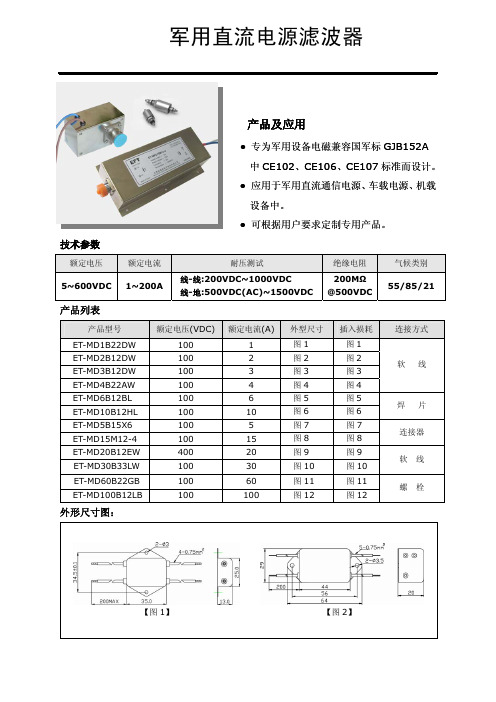
军用直流电源滤波器
产品及应用
●专为军用设备电磁兼容国军标GJB152A 中CE102、CE106、CE107标准而设计。
●应用于军用直流通信电源、车载电源、机载设备中。
●可根据用户要求定制专用产品。
技术参数
额定电压
额定电流
耐压测试
绝缘电阻 气候类别 5~600VDC 1~200A
线-线:200VDC~1000VDC 线-地:500VDC(AC)~1500VDC
200M Ω @500VDC
55/85/21
产品列表
产品型号
额定电压(VDC)
额定电流(A)
外型尺寸 插入损耗 连接方式
ET-MD1B22DW 1001图1 图1 ET-MD2B12DW 1002图2 图2 ET-MD3B12DW 1003图3 图3 ET-MD4B22AW 1004图4 图4 软 线 ET-MD6B12BL 1006图5 图5 ET-MD10B12HL 10010图6 图6 焊 片 ET-MD5B15X61005图7 图7 ET-MD15M12-410015图8 图8 连接器 ET-MD20B12EW 40020图9 图9 ET-MD30B33LW 100 30 图10 图10 软 线 ET-MD60B22GB 100 60 图11 图11 ET-MD100B12LB
100
100
图12
图12
螺 栓 外形尺寸图:
【图1】 【图2】
【图3】【图4】【图5】【图6】【图7】【图8】
【图11】【图12】
插入损耗:。
MODEC AIR MOTOR 系列 MT 和 MR 用户手册说明书

Manuel utilisateur Mise à jour : 8 November 2010Index1.General description and identification Page: 32.Safety Instructions Page: 43.How to start an air motor Page: 54.Maintenance and repair Page: 95. ATEX certificate Page: 116.Notes Page: 12Manuel utilisateur Mise à jour : 8 November 2010DECLARATION OF INCORPORATION OF PARTLY COMPLETED MACHINERY (Directive 2006/42/EC of the European parliament and of council of 17 May 2006) and EC DECLARATION OF CONFORMITY (ATEX DIRECTIVE 94/9/EC)I undersigned Pierre-Yves Cote / President of Modec air motors / Z.I. Les Bosses 26800 Etoile sur Rhône / France / Siret : 493 748 917 000 17⇒Declare that the following ranges of air motors:∙MT05, MT07, MT10, MT20, MT25, MT30, MT40, MR07, MR08, MR10,MR20, MR25, MR30, MR40, NT05, NT07, NT10, NT20, NT25, NT30, NT40, NR07, NR08, NR10,NR20, NR25, NR30, NR40.∙Offering under 6 bars from 40 Watts to 3500 Watts∙Made of one pneumatic section, one planetary gear box, one mounting flange and one output shaft.Applies with the essential requirements of the Directive 2006/42/EC of the European parliament and of council of 17 May 2006. The relevant documentation is complied in accordance with part B of Annex VII of the above Directive.Those documents can be transmitted in response to a reasoned request by the national authorities.Our motors considered as partly completed machinery must not be put into service until the final machinery into which it is to be incorporated has been declared in conformity with the provisions of this Directive.⇒Declare that the following ranges of air motors:∙MT05, MT07, MT10, MT20, MT30, MR07, MR08, MR10,MR20, MR30,∙Offering under 6 bars from 40 Watts to 3500 Watts∙Made of one pneumatic section, one planetary gear box, one mounting flange and one output shaft.∙Marked with the following mention : MODEC/France/2009 / Modec part number / ATEX II 2 G/D c IIC T6/T4 / LCIE 09 ATEX 1003XApplies with the essential requirements of the Directive 94/9/EC : Directive 94/9/EC of the European Parliament and the Council of 23 March 1994 on the approximation of the laws of the Member States concerning equipment and protective.Origin : All motors have been produced and mounted in France.Etoile sur Rhône November 3rd , 2010Pierre-Yves Cote / President / Modec S.A.S.Manuel utilisateur Mise à jour : 8 November 20101 – General description and identification of motorsMODEC air motors are composed of the following:1. A Pneumatic part linked to the power range.2. A Planetary geared reduction system enabling to adapt torque and speed.3. A Mounting flange.4. A shaft, it can be of various types.Your air motor is the combination of these 4 items. The numbering MODEC identifies precisely all the components of your motor..Reference motor:Motor serial number:Date : Stamp :Manuel utilisateur Mise à jour : 8 November 20102 - Safety InstructionsTo read carefully prior to any installation, use and maintenance.∙Changes may be made to the motors described in this document. We reserve the right to change, without notice, the characteristics thereof.∙This document is unique and it is the property of MODEC Company. It can not be corrected, modified or duplicated without written agreement.∙This document does not replace the security rules set by the Labor Code or any other laws applicable in the place of use of the motor.Operators using or near the motors must bear the following protections, depending on the site or they are used. Additional protections can be expected.This operator’s manual must always be available near the place of use of motor. It must be read and used by all persons connected with the wok carried out by the latter.∙All changes to motors or its accessories most be approved by the manufacturer by writing.∙Motors, during use are sources of noise. It is recommended to use adequate hearing protection.∙Excessive lubrication can cause damage to the operator, because it involves spraying in its immediate environment of a certain quantity of oil in the air from the motor.∙Motor can produce vibrations. Frequent and prolonged exposure to these high intensity vibrations can cause disorders and diseases that affect especially hands andarms. The effects are not yet well known because they depend on several factors,including: the type of work, the physical conditions of the operator, the duration andexposure conditions.* Lack of compliance with instructions contained in this manual, as well as changes, omissions and use of spare parts that don’t meet the specifications detailed in this manual, relieves the manufacturer from any liability relating to proper use, proper functioning and protection of persons and equipment.Manuel utilisateur Mise à jour : 8 November 20103 – How to start an air motor✓Transporting the motor:On receipt of the motor, make sure that the package and the motor have not been damaged. If any damage is noticed, please contact MODEC. Keep the package until you have set up the motor. When moving to another workstation or another workshop, make sure that you cautiously transport the motor. Use an appropriate package to avoid damaging the motor.✓Installing the motorPatterns of pneumatic feeding of MODEC motors (see the diagrams below)Before to make any operation to start an air motor, it must ensure good quality of network air to protect the motor against pests, dirt and rusting.This includes:∙The supply pressure must never exceed the maximum working pressure of the motor is6 bars, whichever is greater using a pressure regulator∙The flow must be sufficient for the motor∙The installation of a lubricant filter between the plug and the input fitting is essential for the motor with 50 micron filtration and lubrication oil 50 mm3 per m3 of air consumed.∙It is advisable to connect each motor to the supply system by inserting a switch tire safety, in order to avoid any whiplash that could cause a pipe broke or detached ∙Don’t use tubes damaged or worn. Inspect carefully feeding tubes before use: a ruptured tube can cause some damage.∙The feeding tube should be oil resistant, abrasion and adapted to the pressure of the motor.∙The excessive length of tube should be avoided.Manuel utilisateurMise à jour : 8 November 20101.Filter2.Pressure regulator3. Lubricating system4. Flow control system5. Distributor 3/26. Non reversible motor Direction of rotation left or rightDirection of rotation reversible For a reversible engine it is necessary that the opposite opening of the feed in air is for the exhaustManuel utilisateur Mise à jour : 8 November 2010Motor lubricationTo maximize the life of your motor and guarantee their full power operation, it must be absolutely lubricated with 50 mm3 per m3 of air,see table below (1 drop = 15 mm3).The pneumatic oil used should have a viscosity between 22 and 46 cst depending on the temperature of motor operation (e.g. 40 ° C the viscosity of the oil should be between 22 and 30 cst) and having a temperature self-ignition above 260 ° CMotor with « KIT NO LUB »The motors without lubrication don’t require any additional oil in the air. However, beware the quality of the area (watch the water content in the air system)Manuel utilisateur Mise à jour : 8 November 2010✓Installing the motor after having validated the previous step ∙Set the motor on your system through the flange supplied by MODEC.∙Never operate the engine without a proper system to isolate the source.∙Clean the feeding tube of dirt and condensation and fittings.∙Connect the feeding tube to the engine before opening the air supply.∙Never forget that the tube should be examined carefully after use.✓Starting up of the motor after having validated the previous stepsNote that MODEC motors are always tested and lubricated on manufacturing process.∙First starting up, make pulses of successive air in the motorVerify that there is not any malfunction of the motor (sounds abnormal or excessive heating)✓Motor starts in ProductionAt the start of motor in production, it is important to ensure continuity in time of validation of previous steps.✓Long inactivity from the motor∙When a long inactivity from an air motor, this one must keep out from an humid environment to avoid the formation of rust on the internal mechanical parts because it can reduce this early life.∙To return to service the motor, insert 3 drops of pneumatic oil into the air inlet and repeat the instructions of starting up described above.✓Recycling your motor∙ A pneumatic tool is made up of steel, cast-iron, brass and plastic components. All these items can be salvaged and are not dangerous for the surroundings and/or the safety of the staff. You may separate the different materials in order to reuse them.Manuel utilisateur Mise à jour : 8 November 20104 – Maintenance and repair procedure of an air motorGeneral recommendation∙Consider all the regulations put in place regarding safety and hygiene at work, and instructions in effect in the local framework for security including the conditions of the workplace, clothing and equipment of individual protection of the operator required by all applicable regulations.∙It is recommended that you keep a maintenance log for each operation made on the motor.Prevent any presence of foreign body in the system, by providing a clean work surface to protect sensitive internal moving parts against, contamination by dirt and foreign material use during installation and reassembly because it may cause a deterioration of mechanical parts.∙The air motor maintenance will be performed by persons competent and trained by MODEC or our department after sales service is available for this purpose.∙It is advisable to check and clean the air motor every six months when used daily, as recommended to clean the coupling-filter fitting the motor.∙ In case of engine malfunction after a period of inactivity, a few drops of oil into the fitting of air branch connection.∙Unplug systematically motor branch connection before starting an operation of substitution, adjustment, maintenance or dismantling.∙After every maintenance, the engines will be tested to verify their good functioning.Use only replacement parts and original elements ensuring the maintenance, lubrication and sealing recommended by the manufacturer.Manuel utilisateurMise à jour : 8 November 2010 Right angle type MR greasingYour motor has been delivered with a greased bevel gear. The frequency of greasing operation is depending of the motor use, which are identified in 3 stages: ∙ low load ∙ medium load∙ heavy load and/or shockRight angle greasingGammes de moteurs Air motors ranges Contraintes d'utilisations Contraint of use FrequenceFrequencyQuantités Quantity’sMarque recommandée Brand recommendationMR07;08;09;10;20;25Faible Chargelow load1000 H 10 to 20 mLORAPI 606 CTDMEP 2Charge moyenne Medium load500 H Charge importante et choc Heavy load and Shock200 H MR26; 30;40Faible Charge low load900 H40 to 60 mL ORAPI 606 CTDMEP 2Charge moyenne Medium load400 H Charge importante et choc Heavy load and Shock150 HMT moto reducer type greasingYour motor has been delivery with permanent greasing, if required the reducer can be re-greased:- old grease must be removed carefully- 50 to 70mL of grease 606 ORAPI CTDMEP 2 has to be distribute uniformly inside the reducerManuel utilisateur Mise à jour : 8 November 2010In case of failure, rapid diagnosisIf after all checks listed in this manual your motor is not working properly, please contact the "Service After Sale" from MODEC which tells you what to do. ……………………………………………………………………………………………………………………………………………………………………………………………………………………………………………………………………………………………………………………………………………………………………………………………………………………………………………………………………………………………………………………………………………………………………………………………………………………………………………………………………………………………………………………………………………………………………………………………………………………………………………………………………………………………………………………………………………………………………………………………………………………………………………………………………………………………………………………………………………………………………………………………………………………………………………………………………………………………………………………………………………………………………………………………………………………………………………………………………………………………………………………………………………………………………………………………………………………………………………………………………………………………………………………………………………………………………………………………………………………………………………………………………………………………………………………………………………………………………………………………………………………………………………………Manuel utilisateur Mise à jour : 8 November 2010…………………………………………………………………………………………………5 - ATEX certificateThe certificate below is valid only if the motor has the legal mention engraved according to the ATEX directive EN-13463-1 of 2002.Manuel utilisateur Mise à jour : 8 November 2010NOTES …………………………………………………………………………………………………………………………………………………………………………………………………………………………………………………………………………………………………………………………………………………………………………………………………………………………………………………………………………………………………………………………………………………………………………………………………………………………………………………………………………………………………………………………………………………………………………………………………………………………………………………………………………………………………………………………………………………………………………………………………………………………………………………………………………………………………………………………………………………………………………………………………………………………………………………………………………………………………………………………………………………………………………………………………………………………………………………………………………………………………………………………………………………………………………………………………………………………………………………………………………………………………………………………………………………………………………………………………………………………………………………………………………………………………………………………………………………………………………………………………………………………………………………………………………………………………………………………………………………………………………………………………………………………………………………………………………………………………………………………………………………………………………………………………………………………………………………………………………………………………………………………………………………………………………………………………………………………………………………………………………………………………………………………………………………………………………………………………………………………………………………………………………………………………………………………………………………………………………………………………………………………………………………………………………………………………………………………………………………………………………………………………………………………………………………………………………………………………………………………………………………………………………………………………………………………………………………………………………………………………………………………………………………………………………………………………………………………………………………………………………………………………………………………………………………………………………………………………………………………………………………………………………………………………………………………………………………………………………………………………………………………………………………………………………………………………………。
powersoft_K系列使用手册_中文版.pdf说明书
K 系列功放K2 / K2 DSP + AESOP K3 / K3 DSP + AESOP K6 / K6 DSP + AESOP K8 / K8 DSP + AESOP K10 / K10 DSP + AESOP K20 / K20 DSP + AESOP用户手册V 2.32012年11月powersoft_K Series_uguide _en_v2.4© 2012 Powersoft DO000044REV 02Powersoft • Via Enrico Conti, 5 • 50018 Scandicci (FI) • Italy • +39055 735 0230 • sales@powersoft.it • K系列用户手册1 警告 (5)1.1重要的安全指示 (5)1.2认证 (5)1.3警告提示 (6)1.3.1 放置 (6)1.3.2安装注意事项 (6)1.4安全规则 (6)1.5 音箱损害 (6)1.6 音箱输出电击危险 (7)2 前后面板参考图 (8)3 欢迎 (11)3.1介绍 (11)3.2 K系列 (11)3.3音质更佳,重量更轻 (11)3.4 确保表演无间断正常运转 (11)4 安装 (11)4.1开包 (11)4.2安装 (12)4.3散热 (12)4.4操作防范措施 (12)4.5接地 (12)4.6交流电源连接 (12)5连接和操作 (13)5.1连接音频输出 (13)5.1.1 模拟连接 (13)5.1.2 AES/EBU 连接 (14)5.2 连接音频输出 (14)5.3内部信号通路极性 (15)5.3.1 V ext (15)5.3.2串行连接 (15)5.3.3 以太网连接 (16)5.4功放系统搭建与设置 (17)5.4.1 简介 (17)5.4.2 主屏幕与LED条 (17)5.5 前面板按钮 (18)6主菜单 (18)7功放设置 (21)7.1 输出衰减 (21)7.2 输入增益/灵敏度 (21)7.3 输入选择 (21)7.4 最大输出电压 (21)7.5 最大电源电流 (22)7.6 削波限幅器通道1-通道2 (22)7.7 门限通道1-通道2 (22)7.9 空载模式 (23)8 DSP设置 (23)8.1 DSP处理链 (23)8.2 DSP设置菜单 (24)8.2.1 通用设置 (24)8.2.1.1 源选择 (24)8.2.1.2 AES3 (24)8.2.1.3 增益微调(dB) (24)8.2.1.4 如无连接 (24)8.2.1.5 交叉限幅 (25)8.2.1.6 声音速度(m/s) (25)8.2.2 通道设置 (25)8.2.2.1 均衡 (25)8.2.2.2低通滤波器(和高通滤波器) (27)8.2.2.3极性 (27)8.2.2.4通道延时 (27)8.2.2.5增益 (27)8.2.2.6限幅器 (27)8.2.2.7阻尼控制 (31)8.3通道1/通道2设置 (31)8.3.1辅助延时 (31)8.3.2 诊断 (31)8.4输入均衡 (32)8.5 重置输入部分 (32)8.6 重置输出部分 (32)9网络操作 (32)9.1 AESOP概览 (32)9.1.1 数据流 (32)9.1.2 音频 (33)9.1.3 网络连接:以太网,AES3单向模式和中继模式 (33)9.2 网络稳健性 (35)9.3 网络连接 (36)10 KAESOP网络设置菜单 (39)10.1 设备模式 (39)10.2 寻址模式 (39)10.3 设置地址 (40)10.4 显示网络配置 (40)10.5 音频 (40)10.5.1 音频源选择 (40)10.5.2 音频源模式 (40)10.5.3 增益微调 (40)10.5.4 如无连接 (40)11 显示 (40)11.1 输出电平表 (40)11.2 温度 (41)11.3 电源电平表 (41)11.4 功放名称 (41)12.1 锁定预设 (41)12.2 锁定预设库规模 (42)12.3 调用本地预设 (42)12.4 保存本地预设 (42)12.5 更改锁定密码 (43)12.6 清除所有预设 (44)13 系统搭建 (44)13.1 硬件信息 (44)13.2 硬件监控器 (44)13.3 LCD对比度 (45)13.4 键锁定和设置键锁密码 (45)13.5 单一通道静音 (45)14 保护 (45)14.1打开/关闭静音 (45)14.2 短路保护 (45)14.3 过热保护 (46)14.4 直流故障保护 (46)14.5 输入/输出保护 (46)15 用户维修保养 (46)15.1 清洁 (46)15.2 维修 (46)15.3 除尘 (46)16 附录 (46)16.1 自定义以太网/AES3组合接头盒 (46)16.2 功放错误代码 (47)16.3 智能卡功能 (47)16.4 控制软件 (48)16.4.1 Powersoft的Armonía Pro Audio Suite (48)16.4.2 第三方控制 (48)17 技术参数表 (49)17.1 K2 (51)17.2 K2 DSP+AESOP (53)17.3 K3 (55)17.4 K3 DSP+AESOP (57)17.5 K6 (59)17.6 K6 DSP+AESOP (61)17.7 K8 (63)17.8 K8 DSP+AESOP (65)17.9 K10 (67)17.10 K8 DSP+AESOP (69)17.11 K20 (71)17.12 K20 DSP+AESOP (73)K 系列用户手册1 警告1.1重要的安全指示警告:为减少电击风险,请勿试图打开本设备的任何部件。
Aputure MT Pro产品说明书

MT Pro Product ManualEnglishIntroductionThank you for purchasing the Aputure® MT Pro.Aputure MT Pro is a full spectrum mini LED tube light for cinematographers andlighting professionals. Featuring total color and pixel control in a compact form factor, the MT Pro is your new filmmaking paintbrush.Granting you true creative freedom, the MT Pro utilizes advanced wireless connectivity with our innovative Sidus Link mobile app and the industry-standard Lumenradio CRMX for wireless DMX adjustability.Meet the MT Pro. All the color you need in the palm of your hand.IMPORTANT SAFETY INSTRUCTIONSWhen using this unit, basic safety precautions should always be followed, including the following:1. Read and understand all instructions before using.2. Close supervision is necessary when any fixture is used by or near children. Do not leave the fixtureunattended while in use.3. Care must be taken as burns can occur from touching hot surfaces.4. Do not operate the fixture if a cord is damaged, or if the fixture has been dropped or damaged, until it has been examined by qualified service personnel.5. Let the lighting fixture cool completely before storing. Unplug the power cable from lighting fixture beforestoring and store the cable at assigned space of the carrying case.6. To reduce the risk of electric shock, do not immerse this fixture in water or any other liquids.7.Toreducetheriskoffireorelectricshock,*******************************************************the lighting fixture to qualified service personnel when service or repair is required. Incorrect reassemblymay cause electric shock when the lighting fixture i s in use.8. The use of any accessory attachment not recommended by the manufacturer may increase the risk of fire,electric shock, or injury to any persons operating the fixture.9. Please do not place the LED lighting fixture near any flammable object.10. Only use a dry microfiber cloth to clean the product.11. Please do not use the light fixture in wet condition on account of electric shock may be caused.12. Please have the product checked by an authorized service personnel agent if the product has a problem.Any malfunctions caused by unauthorized disassembly are not covered by the warranty. The user may payfor maintenance.13. We recommend only using the original Aputure cable accessories. Please note that any malfunctions acaused by using unauthorized accessories are not covered by the warranty. The user may pay formaintenance.14. This product is certified by RoHS, CE, KC, PSE, and FCC. Please operate the product in full compliance withrelevant country's standards. Any malfunctions caused by incorrect use are not covered by warranty. Theuser may pay for maintenance.15. The instructions and information in this manual are based on thorough, controlled company testingprocedures. Further notice will not be given if the design or specifications change.SAVE THESE INSTRUCTIONSFCC Compliance StatementIf this equipment does cause harmful interference to radio or television reception, which can be determined by turning the equipment off and on, the user is encouraged to try reorient or relocate the receiving antenna.1. Increase the separation between the equipment and receiver.2. Connect the equipment to an outlet on a different circuit than the receiver is connected to.3. Consult the dealer or an experienced radio/TV technician for helpRF Warning Statement:This device has been evaluated to meet general RF exposure requirements.* You can find a detailed user guide for this device on our website .Components ListPlease make sure all accessories listed below are found before using. If not, contact your seller immediately.Type-C Charging Cable 1m (1 pc)Carrying Case (1 pc)Desktop Tripod (1 pc)* The illustrations in the manual are only diagrams for reference. Due to the continuous development of new versions of the product, if there are any differences between the product and the user manual diagrams,please refer to the product itself.Installations1. Magnets2. Desktop TripodHorizontal InstallationVertical InstallationOperationsAs the light is charging, the on-screen battery level indicator will animate to show the battery's status. After the * Please use the included USB-C cable to charge MT Pro. Using a different cable won’t guarantee optimal charging.* Supports 5V/2A charging via charger or power banks.* Charging rate will slow down when the light is powered on. Turn the light off for optimal charging.3. Manual Control 3.1 UI IntroducingCurrent mode Battery level Battery remaining time Wireless connection status3.2 MenuPress MENU to access the system menu, rotate and press the control wheel to select CCT / HSI / RGB / FX /Custom FX / DMX Setting / CRMX Setting / BT Setting / Language / Factory Reset / Product Info / Screensaver / Exit .3.4 HSIPress MENU to access the system menu, rotate and press the control wheel to select HSI mode.INT (Intensity): 0.0 - 100.0 %HUE (Hue): 0.1 - 360.0°SAT (Saturation): 0.0 - 100.0 %CCT (Correlated Color Temp.): 2000 K - 10000 K3.5 RGB Press MENU to access the system menu, rotate and press the control wheel to select RGB mode.INT(Intensity): 0.0 - 100.0 %R (Red): 0.0 - 100.0 %G (Green): 0.0 - 100.0 %B(Blue): 0.0 - 100.0 %3.6 FX Press MENU to access the system menu, rotate and press the control wheel to select FX mode.3.6.1 System FX Press the control wheel to select system FX, rotate and press the control wheel to selectPaparazzi II / LightningIII / TV IV / Fire III / Faulty Bulb III / Pulsing III / Cop car III / Party Lights II/ Fireworks II.* Please refer to page 12-14 for detailed parameter info3.3 CCTPress MENU to access the system menu, rotate and press the control wheel to select CCT mode.INT (Intensity): 0.0 - 100.0 %CCT (Correlated Color Temp.): 2000 K - 10000 KG/M (Green / Magenta adjustment): -1.0 - +1.03.6.2 Pixel FXPress the control wheel to select system FX, rotate and press the control wheel to select Color Fade / ColorCycle / One Pixel Chase / Two Pixel Chase / Three Pixel Chase / Rainbow / Pixel Fire.3.7 Custom FXPress MENU to access the system menu, rotate and press the control wheel to select Custom FX. You can choose to enter Picker FX or Music FX. Each type can save 10 custom FXs. In the name of each FX, "NO FX"means unsaved FX, and "Untitled" means saved FX.3.8 DMX SettingPress MENU to access the system menu, rotate and press the control wheel to select DMX Setting.DMX Address: Choose the DMX address of MT Pro, press and hold the control wheel for 2 seconds to lock/unlock the DMX address (Prevent accidental touch to exit DMX mode)DMX Profiles: Rotate the control wheel and press to choose DMX profile.DMX Loss Behavior:1. Hold Last Setting: After DMX signal is lost, remember the last control setting.2. Black Out: when the DMX signal is lost, it will be Black out3. Fade To Black: after DMX signal is lost, it will fade to Black in 60 seconds4. Hold 2min & Fade Out: After the DMX signal is lost, keep the last control setting for two minutes, and thenFade to Black within 60 seconds* The fade-out time decreases as the percentage of brightness decreases. When the brightness output is 100%, the fade-out time is 60 seconds, which decreases in sequence.* If the signal is reconnected, the DMX console will continue to maintain the signal output as same as before.* Please refer to page 12 - 14 for detailed parameter info3.9 CRMX SettingPress MENU to access the system menu, rotate and press the control wheel to select CRMX Setting mode. CRMX Status: When CRMX Status is ON, it will continuously search for a pairable signal in the background to connect.Unpair: Unpair will disconnects the currently established connection so that other signal transmitters can be paired.3.10 BT SettingPress MENU to access the system menu, rotate and press the control wheel to select BT Setting mode.BT Status: Rotate and press the control wheel to turn on/off Bluetooth.BT Reset: Reset the MT Pro Bluetooth connection, and your mobile phone or tablet will be able to connect to and control the light with Sidus Link App.BT UID: See the Bluetooth Unique Identifier.3.11 LanguagePress MENU to access the system menu, rotate and press the control wheel to select Language, Rotate and press the control wheel to select English or Simplified Chinese.3.12 Factory ResetPress MENU to access the system menu, rotate and press the control wheel to select Factory Reset. Factory Setting:Light Mode: Intensity 50%, CCT 5600K;Language: English;BT Status: ON;DMX: Address 001, Profile CCT&RGB, Hold Last Setting.YES NO3.13 Product InfoPress MENU to access the system menu, rotate and press the control wheel to select Product Info to see Firmware Version / Hardware Version.3.14 ScreensaverPress MENU to access the system menu, rotate and press the control wheel to select Screensaver mode. You.can choose to turn the screensaver on after 30/60/120 minutes or turn it off3.15 ExitPress MENU to access the system menu, rotate and press the control wheel to select Exit. It will go back to the previous interface.4. Wired DMX Control4.1 Connect to a standard DMX controllerDaisy chaining multiple lights over DMX* USB-C to 5-Pin XLR In & Out adapter sold separately.4.2 DMX Interface InfoSignal CommonData 2+ (Optional Secondary Data Link)Data 2- (Optional Secondary Data Link)Data 1+ (Primary Data Link)Data 1- (Primary Data Link)Signal CommonData 2+ (Optional Secondary Data Link)Data 2- (Optional Secondary Data Link)Data 1+ (Primary Data Link)Data 1- (Primary Data Link)4.3 DMX ProfileThe MT Pro offers a variety of DMX modes. Please find a detailed overview of all DMX modes in the document, DMX Chart is available for free download on the Aputure official website https://.5. Using the Sidus Link APPYou can download the Sidus Link app from the iOS App Store or Google Play Store for enhancing the functionality of the light. Please visit Sidus.link/app/help for more details regarding how to use the app to control your Aputure lights.Sidus.link/app/helpGet Sidus Link App SpecificationsPower InputCRI TLCI CQS CCT Range Weight Control Methods9W 9598962000 - 10000 K 391 g / 0.86 lbs7.5W 3.7 V / 4200 mAh 100%: 2 hours 2 hours(USB DC 5 V / 2 A)-10°C - +45°CPower Output Battery Battery Runtime Charging time Operating Temperature Dimensions (L x W x H)Sidus Link APP , DMX,CRMX, On-board40 x 35 x 300 mm / 1.57 x 1.38 x 11.81 inPhotometricsCCT 2700K 3200K 5600K 6500K 7500K 10000KRGB Distance0.5m1m0.5m1m0.5m1m0.5m1m0.5m1m0.5m1m0.5m1m0.5m1m0.5m1mFabric Grid471 lux / 43fc128 lux / 11fc476 lux / 44fc129 lux / 11fc523 lux / 48fc142 lux / 13fc549 lux / 51fc149 lux / 13fc515 lux / 47fc140 lux / 13fc460 lux / 42fc125 lux / 11fc142 lux / 13fc37 lux / 3fc225 lux / 20fc61 lux / 5fc48 lux / 4fc12 lux / 1fcBare Bulb526 lux / 48fc143 lux / 13fc532 lux / 49fc144 lux / 13fc585 lux / 54fc159 lux / 14fc614 lux / 57fc167 lux / 15fc577 lux / 53fc157 lux / 14fc514 lux / 47fc139 lux / 12fc151 lux / 14fc42 lux / 3fc253 lux / 23fc70 lux / 6fc56 lux / 5fc18 lux / 1fc* This data is based on average brightness measurements, there will be slight variations between lights.Detailed Parameters of FX Control System FXINT CCTG/M Intervals Status 0% - 100%2000 K - 10000 K-1.0 - +1.0[ 0.2S - 1.0S ] - [ 2.0S - 18.0S ] Stop / LoopPaparazzi ⅡINT Mode Intervals Status 0% - 100%CCTHSI[ 1.5S - 3.0S ] - [ 2.6S - 30.0S ] Stop / Trigger /LoopLightning Ⅲ2000 K - 10000 K1 - 360°G/M -1.0 - +1.0SAT 0 - 100 %CCT 2000 K - 10000 KINTModeIntervalsStatus0% - 100%CCTRangeHSIRange[ 0.5S - 2S ] - [ 5.0S - 15.0S ]Stop / LoopTV Ⅲ[ 2000 K - 9900 K ] -[ 2100 K - 10000 K ][ 0° - 359° ] - [ 1° - 360 °]G/M -1.0 - +1.0SAT 0 - 100 %CCT 2000 K - 10000 KINTModeFRQStatus0% - 100%CCTRangeHSIRange60 - 240 /minStop / LoopFire Ⅲ[ 1400 K - 9900 K ] -[ 1800 K - 10000 K ][ 0° - 359° ] - [ 1° - 360 °]G/M -1.0 - +1.0SAT 0 - 100 %CCT 2000 K - 10000 KINTModeIntervalsStatus0% - 100%CCTHSI[ 0.3S - 1.8S ] - [ 1.8S - 7.5S ]Stop / LoopFaulty Bulb Ⅲ2000 K - 10000 K1 - 360°G/M -1.0 - +1.0SAT 0 - 100 %CCT 2000 K - 10000 KINTModePlusesStatus0% - 100%CCTHSI10 - 200 /minStop / LoopPulsing Ⅲ2000 K - 10000 K1 - 360°G/M -1.0 - +1.0SAT 0 - 100 %CCT 2000 K - 10000 KPixel FX INTColorsFRQStatus0% - 100%R / B / R+B / B+W /R+B+WSingle / Double / Quad / Quint / Quint all / CycleStop / LoopCop Car ⅢINT SAT Speed Status 0% - 100%0 - 100%1 - 60S Stop / LoopParty Light ⅡINT Mode Intervals Status 0% - 100%CCT / HUE / CCT+HUE [ 0.5S - 9S ] - [ 2.0S - 11.0S ] Stop / LoopFirework ⅡINT Color No Color 1 Color 2 Color 3 Color 4 Speed Move Status 0% - 100%1 /2 /3 / 4Black /HUE: 30° / 60° / 90° / 120° / 150° / 180° / 210° / 240° / 270° / 300° / 300° /360° /CCT: 2500K 3200K / 4300K / 5600K / 6500K / 7500K1 - 640 cm/sLeft / RightPlay / Pause / StopColor FadeINT Color No Color 1 Color 2 Color 3 Color 4 Transfer Speed Move Status 0% - 100%1 /2 /3 / 4Black /HUE: 30° / 60° / 90° / 120° / 150° / 180° / 210° / 240° / 270° / 300° / 300° / 360° /CCT: 2500K 3200K / 4300K / 5600K / 6500K / 7500KStep / Smooth0.1 - 10.0SLeft / RightPlay / Pause / StopColor CyclePixel INT Bkgd INT Pixel Size Departure Color 1 Color 2 Blackground Speed Move Status 0% - 100%0% - 100%S / M / L1 Way /2 WayBlack (Blackground Only )/HUE: 30° / 60° / 90° / 120° / 150° / 180° / 210° / 240° / 270° / 300° / 300° / 360° /CCT: 2500K 3200K / 4300K / 5600K / 6500K / 7500K1 - 640 cm/sLeft / Right / Loop (1 Way) Bounce / Cross (2 Way)Play / Pause / StopOne Pixel ChasePixel INT Bkgd INT Pixel Size Departure Color 1 Color 2 Color 3 Color 4 Blackground Speed Move Status 0% - 100%0% - 100%S / M / L1 Way /2 WayBlack (Blackground Only )/HUE: 30° / 60° / 90° / 120° / 150° / 180° / 210° / 240° / 270° / 300° / 300° /360° /CCT: 2500K 3200K / 4300K / 5600K / 6500K / 7500K1 - 640 cm/sLeft / Right / Loop (1 Way) Bounce / Cross (2 Way)Play / Pause / StopTwo Pixel ChasePixel INT Bkgd INT Pixel Size Departure Color 1 Color 2 Color 3 Color 4 Color 5 Color 6 Blackground Speed Move Status 0% - 100%0% - 100%S / M / L1 Way /2 WayBlack (Blackground Only )/HUE: 30° / 60° / 90° / 120° / 150° / 180° / 210° / 240° / 270° / 300° / 300° /360° /CCT: 2500K 3200K / 4300K / 5600K / 6500K / 7500K1 - 640 cm/sLeft / Right / Loop (1 Way) Bounce / Cross (2 Way)Play / Pause / StopThree Pixel ChaseINT Speed Move Status 0% - 100%1 - 640 cm/sLeft / RightPlay / Pause / StopRainbowINT Range Bkgd INT Fire 1 BlackgroundFrequency Move Status [ 0% - 75% ] - [ 25% - 100% ]0% - 100%Black /HUE: 30° / 60° / 90° / 120° / 150° / 180° / 210° / 240° / 270° / 300° / 300° /360° /CCT: 2500K 3200K / 4300K / 5600K / 6500K / 7500K1 - 10 HzHorizontal / VerticalPlay / Pause / StopPixel Fire。
- 1、下载文档前请自行甄别文档内容的完整性,平台不提供额外的编辑、内容补充、找答案等附加服务。
- 2、"仅部分预览"的文档,不可在线预览部分如存在完整性等问题,可反馈申请退款(可完整预览的文档不适用该条件!)。
- 3、如文档侵犯您的权益,请联系客服反馈,我们会尽快为您处理(人工客服工作时间:9:00-18:30)。
Thick Film Chip Resistors, Industrial For technical questions contact: ff2bresistors@Document Number: 31011RCWPVishay DaleFEATURES•Operating temperature range: - 55°C to + 150°C•Same materials and construction as MIL-PRF-55342chip resistors•Termination: Tin/Lead wraparound termination overnickel barrier. Also available with Lead (Pb)-freewraparound terminations.•to customer requirements•Size, value, packaging and materials can be customized for special customer requirements.*Consult factory for extended resistance range.**Power rating depends on the max. temperature at the solder point, the component placement density and the substrate material.STANDARD ELECTRICAL SPECIFICATIONSGLOBAL MODEL HISTORICAL MODEL POWER RATING MAXIMUM OPERATINGTEMPERATURE COEFFICIENTTOLERANCE%RESISTANCE RANGE RCWP0402RCWP-04020.0425300100± 1 to ± 10± 1 to ± 10 5.62 - 1M 10 - 1M RCWP0603RCWP-06030.0750300100, 300± 2 to ± 10± 1 to ± 10 3 - 1M 5.62 - 1M RCWP0540RCWP-5400.0840300100, 300± 2 to ± 10± 1 to ± 10 3 - 4.7M 10 - 499K RCWP0550RCWP-5500.1050300100, 300± 2 to ± 10± 1 to ± 10 2 - 4.7M 5.62 - 1M RCWP0575RCWP-5750.1570300100, 300± 2 to ± 10± 1 to ± 10 2 - 10M 5.62 - 1M RCWP5100RCWP-51000.20100300100, 300± 2 to ± 10± 1 to ± 10 3 - 15M 5.62 - 1M RCWP1206RCWP-12060.25100300100, 300± 2 to ± 10± 1 to ± 10 3 - 15M 5.62 - 5.62M RCWP5150RCWP-51500.35125300100, 300± 2 to ± 10± 1 to ± 10 3 - 20M 5.62 - 4.75M RCWP1100RCWP-11000.50100300100, 300± 2 to ± 10± 1 to ± 10 3 - 7.5M 5.62 - 5.62M RCWP7225RCWP-72250.60200300100, 300± 2 to ± 10± 1 to ± 10 3 - 20M 5.62 - 15M RCWP2010RCWP-20100.80200300100, 300± 2 to ± 10± 1 to ± 10 3 - 20M 5.62- 15M RCWP2512RCWP-25121.0200300100, 300± 2 to ± 10± 1 to ± 105 - 20M 5.62 - 15MRCWPThick Film Chip Resistors, IndustrialVishay DaleDocument Number: 31011For technical questions contact: ff2bresistors@DIMENSIONSDIMENSIONS [in millimeters]GLOBAL MODEL A (Len g th)B (Width)C (Hei g ht)D(Top Term)E(Bottom Term)RCWP04020.039 ± 0.003[0.99 ± 0.08]0.020 ± 0.003[0.51 ± 0.08]0.013 ± 0.003[0.33 ± 0.08]0.010 ± 0.005[0.25 ± 0.13]0.010 ± 0.005[0.25 ± 0.13]RCWP05400.055 ± 0.005[1.40 ± 0.13]0.040 ± 0.005[1.02 ± 0.13]0.020 ± 0.005[0.51 ± 0.13]0.010 ± 0.005[0.25 ± 0.13]0.010 ± 0.005[0.25 ± 0.13]RCWP05500.055 ± 0.005[1.40 ± 0.13]0.050 ± 0.005[1.27 ± 0.13]0.020 ± 0.005[0.51 ± 0.13]0.010 ± 0.005[0.25 ± 0.13]0.015 ± 0.005[0.38 ± 0.13]RCWP05750.080 ± 0.005[2.03 ± 0.13]0.050 ± 0.005[1.27 ± 0.13]0.020 ± 0.005[0.51 ± 0.13]0.015 ± 0.005[0.38 ± 0.13]0.015 ± 0.005[0.38 ± 0.13]RCWP06030.063 ± 0.005[1.60 ± 0.13]0.032 ± 0.005[0.81 ± 0.13]0.018 ± 0.005[0.46 ± 0.13]0.012 ± 0.005[0.31 ± 0.13]0.015 ± 0.005[0.38 ± 0.13]RCWP11000.105 ± 0.005[2.67 ± 0.13]0.100 ± 0.005[2.54 ± 0.13]0.020 ± 0.005[0.51 ± 0.13]0.015 ± 0.005[0.38 ± 0.13]0.015 ± 0.005[0.38 ± 0.13]RCWP12060.125 ± 0.005[3.18 ± 0.13]0.063 ± 0.005[1.60 ± 0.13]0.020 ± 0.005[0.51 ± 0.13]0.015 ± 0.005[0.38 ± 0.13]0.015 ± 0.005[0.38 ± 0.13]RCWP20100.197 ± 0.006[5.00 ± 0.15]0.098 ± 0.005[2.49 ± 0.13]0.020 ± 0.005[0.51 ± 0.13]0.020 ± 0.005[0.51 ± 0.13]0.020 ± 0.005[0.51 ± 0.13]RCWP25120.250 ± 0.006[6.35 ± 0.15]0.124 ± 0.005[3.15 ± 0.13]0.020 ± 0.005[0.51 ± 0.13]0.020 ± 0.005[0.51 ± 0.13]0.020 ± 0.005[0.51 ± 0.13]RCWP51000.105 ± 0.005[02.67 ± 0.13]0.050 ± 0.005[1.27 ± 0.13]0.020 ± 0.005[0.51 ± 0.13]0.015 ± 0.005[0.38 ± 0.13]0.015 ± 0.005[0.38 ± 0.13]RCWP51500.155 ± 0.005[3.94 ± 0.13]0.050 ± 0.005[1.27 ± 0.13]0.020 ± 0.005[0.51 ± 0.13]0.015 ± 0.005[0.38 ± 0.13]0.015 ± 0.005[0.38 ± 0.13]RCWP72250.230 ± 0.005[5.84 ± 0.13]0.075 ± 0.005[1.91 ± 0.13]0.020 ± 0.005[0.51 ± 0.13]0.020 ± 0.005[0.51 ± 0.13]0.020 ± 0.005[0.51 ± 0.13]Legal Disclaimer NoticeVishayNoticeSpecifications of the products displayed herein are subject to change without notice. Vishay Intertechnology, Inc., or anyone on its behalf, assumes no responsibility or liability for any errors or inaccuracies.Information contained herein is intended to provide a product description only. No license, express or implied, by estoppel or otherwise, to any intellectual property rights is granted by this document. Except as provided in Vishay's terms and conditions of sale for such products, Vishay assumes no liability whatsoever, and disclaims any express or implied warranty, relating to sale and/or use of Vishay products including liability or warranties relating to fitness for a particular purpose, merchantability, or infringement of any patent, copyright, or other intellectual property right. The products shown herein are not designed for use in medical, life-saving, or life-sustaining applications. Customers using or selling these products for use in such applications do so at their own risk and agree to fully indemnify Vishay for any damages resulting from such improper use or sale.。